Table of Contents
Advertisement
ControlLogix Voltage/Current Output Module
Catalog Number 1756-OF4
To:
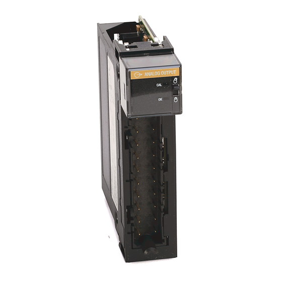
Identify the Module Components
Note the Power Requirements
Install the Module
Key the Module and Removable Terminal Block/Interface Module
Wire the Removable Terminal Block
Wire the Module
Assemble the Removable Terminal Block and the Housing
Install the Removable Terminal Block onto the Module
Check the Indicators
Remove the Removable Terminal Block from the Module
Remove the Module
See Specifications
Obtain a User Manual
This product also has a user manual (pub. no. 1756-UM009). To view
it, visit www.ab.com/manuals or www.theautomationbookstore.com.
To purchase a manual, you can:
• contact your distributor or Rockwell Automation representative
• visit www.theautomationbookstore.com and place an order
• call 800.963.9548 (USA/Canada) or 001.320.725.1574 (outside
USA/Canada)
Installation Instructions
AB PLC
Publication
1756-IN016B-EN-P - November 2003
See page:
7
7
8
9
10
13
15
15
16
17
17
18
Advertisement
Table of Contents

Related Manuals for Allen-Bradley ControlLogix 1756-OF4


Summary of Contents for Allen-Bradley ControlLogix 1756-OF4
- Page 1 Installation Instructions ControlLogix Voltage/Current Output Module Catalog Number 1756-OF4 See page: Identify the Module Components Note the Power Requirements Install the Module Key the Module and Removable Terminal Block/Interface Module Wire the Removable Terminal Block Wire the Module Assemble the Removable Terminal Block and the Housing Install the Removable Terminal Block onto the Module Check the Indicators Remove the Removable Terminal Block from the Module...
-
Page 2: Important User Information
2 ControlLogix Voltage/Current Output Module Important User Information Solid state equipment has operational characteristics differing from those of electromechanical equipment. Safety Guidelines for the Application, Installation and Maintenance of Solid State Controls (Publication SGI-1.1 available from your local Rockwell Automation sales office or online at http://www.ab.com/manuals/gi) describes some important differences between solid state equipment and hard-wired electromechanical devices. -
Page 3: Environment And Enclosure
NOTE: See NEMA Standards publication 250 and IEC publication 60529, as applicable, for explanations of the degrees of protection provided by different types of enclosure. Also, see the appropriate sections in this publication, as well as the Allen-Bradley publication 1770-4.1 ("Industrial Automation Wiring and Grounding Guidelines"), for additional installation requirements pertaining to this equipment. -
Page 4: Removal And Insertion Under Power
IP54 protection when applied in Class I, Zone 2 environments. • This equipment shall be used within its specified ratings defined by Allen-Bradley. • Provision shall be made to prevent the rated voltage from being exceeded by transient disturbances of more than 40% when applied in Class I, Zone 2 environments. -
Page 5: North American Hazardous Location Approval
ControlLogix Voltage/Current Output Module 5 North American Hazardous Location Approval The following information applies Informations sur l’utilisation de cet when operating this equipment in équipement en environnements hazardous locations: dangereux: Products marked “CL I, DIV 2, GP A, B, C, Les produits marqués "CL I, DIV 2, GP A, B, C, D"... - Page 6 6 ControlLogix Voltage/Current Output Module The following information applies Informations sur l’utilisation de cet when operating this equipment in équipement en environnements hazardous locations: dangereux: EXPLOSION HAZARD RISQUE D’EXPLOSION AVERTISSEMENT WARNING • Do not disconnect • Couper le courant ou equipment unless s’assurer que power has been...
-
Page 7: Identify The Module Components
ControlLogix Voltage/Current Output Module 7 Identify the Module Components You received the following components with your order: • 1756-OF4 module • Removable Terminal Block (RTB) door label If you did not receive these components, contact your local distributor Rockwell Automation sales office. This module mounts in a 1756 chassis and uses a separately-ordered RTB or a Bulletin 1492 Interface Module (IFM) to connect all... -
Page 8: Install The Module
8 ControlLogix Voltage/Current Output Module Install the Module You can install or remove the module while chassis power is applied. When you insert or remove the module while backplane WARNING power is on, an electrical arc can occur. This could cause an explosion in hazardous location installations. -
Page 9: Key The Module And Removable Terminal Block/Interface Module
ControlLogix Voltage/Current Output Module 9 Key the Module and Removable Terminal Block/Interface Module Use the wedge-shaped keying tabs and U-shaped keying bands to prevent connecting the wrong wires to your module. Key positions on the module that correspond to unkeyed positions on the RTB. -
Page 10: Wire The Removable Terminal Block
10 ControlLogix Voltage/Current Output Module Wire the Removable Terminal Block Wire the RTB with a 5/16 inch (8mm) maximum flat-bladed screwdriver before installing it onto the module. When you connect or disconnect the Removable WARNING Terminal Block (RTB) while field side power is on, an electrical arc can occur. - Page 11 ControlLogix Voltage/Current Output Module 11 If you cannot ground at the field device, follow these steps: 1. Prepare one end of the cable as shown in step 1. 2. Ground at an earth ground on the chassis as shown below.We recommend grounding the drain wire at the field-side.
- Page 12 12 ControlLogix Voltage/Current Output Module 2. Connect the insulated wires to : • the RTB (as shown below) if the cable is grounded at the field device. • the field device if the cable is grounded at the chassis. Spring Clamp RTB NEMA Screw RTB A.
-
Page 13: Wire The Module
ControlLogix Voltage/Current Output Module 13 Wire the Module You can only connect wiring to your module with an RTB or IFM. 1756-OF4 current wiring example Not used VOUT-0 Not used IOUT-0 Current output load Not used VOUT-1 Not used IOUT-1 Shield Not used ground... - Page 14 14 ControlLogix Voltage/Current Output Module 1756-OF4 voltage wiring example Not used VOUT-0 Not used IOUT-0 – Not used VOUT-1 Shield Not used IOUT-1 ground Not used VOUT-2 Not used IOUT-2 Not used VOUT-3 Not used IOUT-3 40917-M NOTES: 1. Do not connect more than 2 wires to any single terminal. 2.
-
Page 15: Assemble The Removable Terminal Block And The Housing
ControlLogix Voltage/Current Output Module 15 Assemble the Removable Terminal Block and the Housing 1. Align the grooves at the bottom of the housing with the side edges of the RTB. Groove Side edge of the RTB Groove Strain relief area Side edge of the RTB 20852-M 2. -
Page 16: Check The Indicators
16 ControlLogix Voltage/Current Output Module Check the Indicators The indicators show CAL status (green) and a bi-colored LED for module "OK" (red/green). ANALOG OUTPUT 20965-M During power up, an indicator test is done and the following occurs: • The "OK" indicator turns red for 1 second and then turns to flashing green if it has passed the self-test. -
Page 17: Remove The Removable Terminal Block From The Module
ControlLogix Voltage/Current Output Module 17 Remove the Removable Terminal Block from the Module If you need to remove the module, you must remove the RTB first. When you insert or remove the module while backplane WARNING power is on, an electrical arc can occur. This could cause an explosion in hazardous location installations. -
Page 18: Publication 1756-In016B-En-P - November
18 ControlLogix Voltage/Current Output Module 1756-OF4 Specifications Number of Outputs 4 voltage or current outputs Module Location 1756 ControlLogix Chassis Backplane Current 150mA @ 5.1V dc & 120mA @ 24V dc Backplane Power 5.8W Power Dissipation within Module 3.2W – 4 channel current Thermal Dissipation 10.91 BTU/hr. - Page 19 ControlLogix Voltage/Current Output Module 19 RTB Screw Torque (NEMA) 7-9 inch-pounds (0.8-1Nm) Module Keying (Backplane) Electronic RTB Keying User defined RTB and Housing 20 Position RTB (1756-TBNH or TBSH) Conductors Wire Size #22 to #14 AWG (0.324 to 2.08 sq. mm) stranded 3/64 inch (1.2mm) insulation maximum Category Screwdriver Width for RTB...
- Page 20 Surge Transient IEC 61000-4-5: +2kV line-earth (CM) on shielded ports Immunity Conducted RF Immunity IEC 61000-4-6: 10Vrms with 1kHz sine-wave 80%AM from 150kHz to 80MHz Enclosure Type Rating None (open-style) Certifications UL Listed Industrial Control Equipment (when product is marked) CSA Certified Process Control Equipment CSA Certified Process Control Equipment for Class I, Division 2 Group A,B,C,D...
Need help?
Do you have a question about the ControlLogix 1756-OF4 and is the answer not in the manual?
Questions and answers