Allen-Bradley ControlLogix DeviceNet 1756-DNB Installation Instructions Manual
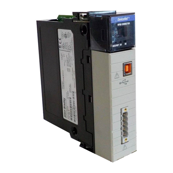
Scanner module
Hide thumbs
Also See for ControlLogix DeviceNet 1756-DNB:
- Configuration manual (68 pages) ,
- Installation instructions manual (68 pages) ,
- Installation instructions manual (28 pages)
Table of Contents
Advertisement
Quick Links
Download this manual
See also:
Configuration Manual
(Catalog Number 1756-DNB)
To the Installer
The 1756-DNB module is a DeviceNet
ControlLogix
chassis and provides DeviceNet monitoring, configuration,
and I/O scan capabilities.
Use this document as a guide to install the ControlLogix DeviceNet
scanner module.
To
Handle the module
Understand Compliance to European Union Directives
Understand the module software features
Identify the module hardware features
Prepare to install the module
Prepare the chassis for installation
Install the module into the chassis
Wire the DeviceNet connector
Connect the module to the DeviceNet network
Apply chassis power
Check module alphanumeric indicators
Use the manual configuration pushbutton
Interpret the node address/status indicator
Interpret the status indicators
Packing Data
Installation Instructions
scanner module that resides in a
AB Parts
PK
See page
2
3
4
6
7
8
8
12
13
14
14
15
16
18
Publication 1756-5.66 – May 1998
Advertisement
Table of Contents

Related Manuals for Allen-Bradley ControlLogix DeviceNet 1756-DNB


Summary of Contents for Allen-Bradley ControlLogix DeviceNet 1756-DNB
- Page 1 Packing Data Installation Instructions (Catalog Number 1756-DNB) To the Installer The 1756-DNB module is a DeviceNet scanner module that resides in a ControlLogix chassis and provides DeviceNet monitoring, configuration, and I/O scan capabilities. Use this document as a guide to install the ControlLogix DeviceNet scanner module.
-
Page 2: Handling The Module
ControlLogix DeviceNet Scanner Module Installation Instructions See page Understand the ControlLogix controller interface Understand CSA Hazardous Location Approval Understand module specifications Handling the Module ATTENTION: The module uses CMOS technology, which is highly sensitive to electrostatic discharge (ESD). ESD may be present whenever you are handling the module. -
Page 3: Understand Compliance To European Union Directives
EN 61131–2 Programmable Controllers, Part 2 – Equipment Requirements and Tests. For specific information required by EN 61131-2, see the appropriate sections in this publication as well as these Allen-Bradley publications: Industrial Automation Wiring and Grounding Guidelines for Noise Immunity, publication 1770-4.1 Guidelines for Handling Lithium Batteries, publication AG-5.4... -
Page 4: Slave Mode
ControlLogix DeviceNet Scanner Module Installation Instructions Understand the Module’s Software Features The 1756-DNB module has the following software features. You activate these features by using DeviceNetManager software (catalog no. 1787-MGR) or RSNetWorx for DeviceNet . For more information, refer to the DeviceNet Manager Software User Manual, publication 1787-6.5.3, the appropriate RSNetWorx for DeviceNet documentation, and the 1756-DNB Scanner Configuration Manual, publication 1756-6.5.15. - Page 5 ControlLogix DeviceNet Scanner Module Installation Instructions Change of State The scanner module can send and receive data on a change of state basis with slave devices that also have this feature. Data is sent: whenever a data change occurs, or at a user-configurable heartbeat rate Change of state increases system performance by reducing network traffic, since data is only sent on an as-needed basis.
-
Page 6: Identify The Module Hardware Features
ControlLogix DeviceNet Scanner Module Installation Instructions Identify the Module’s Hardware Features Use this illustration to identify the external features of the module. Backplane Product Health Connector Label and status Indicators DeviceNet Door Front Panel Label MOD/NET MOD/NET Pushbutton Wiring Color Codes DeviceNet Connector... -
Page 7: Prepare To Install The Module
ControlLogix DeviceNet Scanner Module Installation Instructions Prepare to Install the Module Before you install the module, make sure that you have these components. 1756-DNB module 1756-A4, 1756-A7, 1756-A10, or 1756-PA72 or 1756-PB72 1756-A13 chassis power supply DeviceNet open-style small screwdriver 5- or 10-position connector DeviceNet trunk or drop cable... -
Page 8: Prepare The Chassis For Module Installation
ControlLogix DeviceNet Scanner Module Installation Instructions Prepare the Chassis for Module Installation Before you install the module, you must install and connect a ControlLogix chassis and power supply. To install these products, refer to the installation instructions you received with them. Chassis Power supply... -
Page 9: Determine Module Slot Location
ControlLogix DeviceNet Scanner Module Installation Instructions Determine Module Slot Location This example shows chassis slot numbering in a 4-slot chassis. Slot 0 is the first slot and is always located to the right of the power supply. You can use any size ControlLogix chassis and install the module in any slot. -
Page 10: Controllogix Devicenet Scanner Module Installation Instructions
ControlLogix DeviceNet Scanner Module Installation Instructions Install the Module Align the circuit board with top and bottom guides in the chassis. Circuit board Slide the module into the chassis. Make sure the module properly connects to the chassis backplane. The module is fully installed when it is flush with the power supply or other installed modules. - Page 11 ControlLogix DeviceNet Scanner Module Installation Instructions 11 Remove or Replace the Module (when applicable) Important: If you are replacing an existing 1756-DNB module with another 1756-DNB module and you want to resume identical system operation, you must install the new module in the same slot.
-
Page 12: Wire The Devicenet Connector
ControlLogix DeviceNet Scanner Module Installation Instructions Wire the DeviceNet Connector Use an open-style 5- or 10-position linear plug to connect to the DeviceNet network. An open-style 10-position linear plug is provided with your module. For detailed DeviceNet connection information, see the DeviceNet Cable System Planning and Installation Manual, publication DN-6.7.2. -
Page 13: Connect The Module To The Devicenet Network
ControlLogix DeviceNet Scanner Module Installation Instructions 13 Connect the Module to the DeviceNet Network Attach the connector to the DeviceNet port. 10-position linear plug DeviceNet port connector DeviceNet drop line or trunk line 20441–M 2. Tighten screws as needed. AB Parts Publication 1756-5.66 –... -
Page 14: Apply Chassis Power
ControlLogix DeviceNet Scanner Module Installation Instructions Apply Chassis Power Power supply indicator is green when power supply is working correctly. POWER Check Module Alphanumeric Indicators Check the module alphanumeric indicators to determine if the module is operating. When you apply chassis power, the module alphanumeric indicators cycle through these displays: Firmware major revision DeviceNet... - Page 15 ControlLogix DeviceNet Scanner Module Installation Instructions 15 Using Manual Configuration Pushbutton Operation The 1756-DNB scanner module has a dual-function pushbutton. Without a network connection, when pushed, it displays network baud rate, allowing you to select the rate. With a network connection, when pushed, it displays the MAC ID or network node address, allowing you to select the node address.
-
Page 16: Interpret The Node Address/Status Indicator
ControlLogix DeviceNet Scanner Module Installation Instructions Interpret the Node Address/Status Indicator Your 1756-DNB scanner module has a node address/status indicator that uses alphanumeric displays to indicate diagnostic information about your module. The display flashes at approximately 1 second intervals, depending on network traffic. - Page 17 ControlLogix DeviceNet Scanner Module Installation Instructions 17 Alphanumeric Description Action Code No direct network traffic for scanner None. The scanner hears other network detected. communication. Data size expected by the device does Reconfigure your module for the correct not match scan list entry (node number transmit and receive data sizes.
-
Page 18: Interpret The Status Indicators
ControlLogix DeviceNet Scanner Module Installation Instructions Alphanumeric Description Action Code Network Normal operation. The numeric display Do nothing. Address matches the scanner’s node address on Displays the DeviceNet network. A#00 - A#63 Network User has disabled communication port Reconfigure your module. Check Module Disabled Command Register. -
Page 19: Publication 1756-5.66 - May
ControlLogix DeviceNet Scanner Module Installation Instructions 19 Module/Network (MOD/NET) Status Indicator This bi-color (green/red) LED provides limited device and communication status. The combined Module/Network (or Mod/Net) Status LED indicates whether or not the device has power and is operating properly. Condition Status Indicates... - Page 20 ControlLogix DeviceNet Scanner Module Installation Instructions I/O Status Indicator This bi-color (green/red) LED provides information concerning the status of inputs and/or outputs. The terms ‘inputs’ and ‘outputs’ are being applied loosely here. For example, a Pneumatic Valve Pack device developer may model its product using Discrete Output Point Objects.
- Page 21 ControlLogix DeviceNet Scanner Module Installation Instructions 21 Health (OK) Status Indicator This bi-color (green/red) LED provides device status in the ControlLogix chassis. It indicates whether the device has power and is operating properly. Condition Status Indicates No power applied to device. Apply chassis power. Verify no power module is completely inserted into chassis and backplane.
-
Page 22: Controllogix Controller Interface
ControlLogix DeviceNet Scanner Module Installation Instructions ControlLogix Controller Interface The initial release of the 1756-DNB firmware supports a single default input, output, and status structure over the ControlLogix backplane. These default I/O structures were created to reduce the complexity of connecting DeviceNet I/O and status data with ladder programs. -
Page 23: Module Command Register Bit Definitions
ControlLogix DeviceNet Scanner Module Installation Instructions 23 Module Command Register Bit Definitions Name Description 1 = set for run mode 0 = set for idle mode FAULT 1 = set to fault network Disable_Network 1 = set to disable network Halt_Scanner 1 = set to halt module Reset... -
Page 24: Module Status Register Bit Definitions
ControlLogix DeviceNet Scanner Module Installation Instructions Module Status Register Bit Definitions Name Description 1 = in run mode 0 = in idle mode FAULT 1 = network is faulted Disable Network 1 = network is disabled Device Failure 1 = device failure exists Autoverify Failure 1 = failure is verified automatically Comm Failure... -
Page 25: Csa Hazardous Location Approval
ControlLogix DeviceNet Scanner Module Installation Instructions 25 CSA Hazardous Location Approval CSA certifies products for general use as well as for use in hazardous locations. Actual CSA certification is indicated by the product label as shown below, and not by statements in any user documentation. - Page 26 ControlLogix DeviceNet Scanner Module Installation Instructions Approbation d’utilisation dans les environnements dangereux par la CSA La CSA certifie des produits à utilisation générale aussi bien qu’à utilisation en environnements dangereux. La certification CSA en vigueur est indiquée par l’étiquette produit et non par des indications dans la documentation utilisateur.
-
Page 27: Module Specifications
ControlLogix DeviceNet Scanner Module Installation Instructions 27 Module Specifications Description Value Module Location any slot in the ControlLogix chassis Maximum Backplane Current Load 600mA @ 5.0V dc and 3mA @ 24V dc from ControlLogix chassis backplane Maximum DeviceNet Current Load 90mA maximum @11-25V dc 30mA typical @ 11-25V dc Power Dissipation... - Page 28 ControlLogix and DeviceNetManager are trademarks of Rockwell Automation. RSLogix5000 and RSNetworx for DeviceNet are trademarks of Rockwell Software Inc. DeviceNet is a trademark of Open DeviceNet Vendor Association (ODVA). Worldwide representation. Argentina Australia Austria Bahrain Belgium Brazil Bulgaria Canada Chile China, PRC Colombia Costa Rica Croatia Cyprus Czech Republic Denmark Ecuador Egypt El Salvador Finland France Germany Greece Guatemala Honduras Hong Kong Hungary Iceland India Indonesia...
Need help?
Do you have a question about the ControlLogix DeviceNet 1756-DNB and is the answer not in the manual?
Questions and answers