
Related Manuals for Allen-Bradley Bulletin 160 DeviceNet


Summary of Contents for Allen-Bradley Bulletin 160 DeviceNet
- Page 1 Allen-Bradley Bulletin 160 DeviceNet™ Communication User Manual Module FRN 1.xx – 2.xx...
- Page 2 Important User Information Because of the variety of uses for the products described in this publi- cation, those responsible for the application and use of this control equipment must satisfy themselves that all necessary steps have been taken to assure that each application and use meets all performance and safety requirements, including any applicable laws, regulations, codes and standards.
- Page 3 Summary of Changes Summary of Changes This release of the Bulletin 160 DeviceNet Communication Module User Manual contains the software enhancements of Firmware Version 2.xx and contains new and updated information to the manual. The new and updated information is summarized on the following page.
- Page 4 Setting Baud Rate DeviceNet Parameter Descriptions Chapter 5 160-DN1 EDS Files 5-1 to 5-3 I/O Assemblies Similar to Other Allen-Bradley Drive Products 5-6, B-19, B-21, B-22 Idle Mode Parameter Local Return Parameter 160-DN1 Software Version Parameter Using the 160-DN1 with DeviceNet Scanner...
-
Page 5: Table Of Contents
Table of Contents Using This Manual Preface Manual Objectives..........P-1 Who Should Use This Manual?. - Page 6 Table of Contents DeviceNet Parameter Chapter 5 Descriptions DeviceNet Parameters..........5-1 Electronic Data Sheet .
- Page 7 Table of Contents Specifications Appendix A Electrical ........... . . A-1 Environmental .
-
Page 8: Using This Manual
For information on specific features of the Bulletin 160 SSC drive, refer to the Bulletin 160 SSC User Manual. Important: Read this manual in its entirety before installing, operat- ing, servicing, or initializing the Bulletin 160 DeviceNet Communica- tion Module. Who Should Use This Manual? This manual is intended for qualified personnel. -
Page 9: Reference Manuals
If this manual is not available, please contact either the local Allen-Bradley Distributor or Sales Office and request a copy. Copies may also be ordered from the Automation Bookstore. The Automa- tion Bookstore can be contacted, via the Internet, from the Allen-Bra- dley Home Page at “www.ab.com.”... - Page 10 Component damage may result if ESD control procedures are not followed. If you are not familiar with static control procedures, reference Allen-Bradley Publication 8000-4.5.2, Guarding Against Electrostatic Damage or any other applicable ESD protection handbook.
-
Page 11: Safety Precautions
Using This Manual Safety Precautions (Continued) ATTENTION: The drive contains high voltage capacitors which take time to discharge after removal of mains supply. Before installing or removing the DeviceNet Communication Module, ensure isolation of mains supply from line inputs [L1, L2, L3 (R, S, T)]. Wait one minute for capacitors to discharge to safe voltage levels. -
Page 12: Product Overview
Chapter Product Overview This chapter contains the following information: • The physical layout of the module. • Location of configuration switches. • DeviceNet overview and components. Module Description The Bulletin 160 SSC DeviceNet Communication Module is an optional interface device designed to provide a direct, digital link between DeviceNet devices and the Bulletin 160 SSC drive. -
Page 13: Dip Switches
Product Overview DIP Switches Figure 1.2 Module Rear View The Communication Module has one eight position DIP switch for setting the DeviceNet Node Address and Baud Rate. DIP switches are located on the rear of the module and are only accessible when the module is removed from the Bulletin 160 SSC drive. -
Page 14: Quick Start For
Chapter Quick Start for Experienced Users Objective of This Chapter This chapter can help you start using the Bulletin 160 DeviceNet Communication module. If you have installed or configured a DeviceNet network previously and are familiar with Rockwell Auto- mation DeviceNet modules and drives, this information can help reduce the time of installation. -
Page 15: Procedures
10 point DeviceNet Plug. • Bulletin 160 DeviceNet Communication Module User Manual. If the contents are incomplete, call your local Allen-Bradley representative for assistance. Ensure that the drive is correctly installed and wired. Publication (Stop Input (TB3-7, TB3-8) must be jumpered together 160-SSC to start drive.) -
Page 16: Installation And Wiring
Chapter Installation and Wiring This chapter contains information necessary to: • Meet the requirements of the EMC and Low Voltage directives for CE compliance. • Remove a preinstalled Program Keypad Module or Ready/Fault Indicating Panel. • Configure the Communication Module. •... -
Page 17: Emc Directive 89/336/Eec Compliance
Installation and Wiring EMC Directive 89/336/EEC This product complies with Electromagnetic Compatibility (EMC) Directive 89/336/EEC when conforming with the following installa- Compliance tion requirements: • The essential requirements for a conforming EMC installation for the Bulletin 160 SSC are employed. Refer to the Bulletin 160 SSC User Manual. -
Page 18: Removing Program Keypad Module Or Ready/Fault Panel
Installation and Wiring Removing Program Keypad Module Before installing the Communication Module, it may be necessary to remove a previously installed Program Keypad Module or Ready/ or Ready/Fault Panel Fault panel. ATTENTION: The drive contains high voltage capacitors which take time to discharge after removal of mains supply. -
Page 19: Setting The Devicenet Node Address
Installation and Wiring Setting the DeviceNet Node DIP switches 6 through 1 set the module’s node address using binary addressing. The factory default setting is DeviceNet address 63. Address Figure 3.3 Setting the Node Address DeviceNet Address 000000 - 111111 (0 to 63) ON = 1 OFF = 0 Follow these steps to set the DeviceNet node address:... -
Page 20: Setting The Baud Rate
Installation and Wiring Setting the Baud Rate Dip switches 7 and 8 set the baud rate at which the Communication Module communicates on the network. The factory default setting for baud rate is 125K BPS. Figure 3.4 Setting the Baud Rate Use DIP Switch 8 and 7 for setting the DeviceNet Baud Rate. -
Page 21: Installing The Communication Module
Installation and Wiring Installing the Communication After setting the DIP switches, secure the Communication Module to the drive by following these steps: Module 1. Insert the module, ensuring that the pins on the back of the mod- ule line up with the drive’s expansion port. 2. -
Page 22: Wiring The Devicenet Connector
Installation and Wiring Wiring the DeviceNet Connector Follow these recommendations for communications wiring: • See DeviceNet Cable System for planning and installation of Device Net networks. • Keep communication wiring away from high noise sources such as motor cables. • To increase noise immunity: –... -
Page 23: Connecting The Devicenet Drop Line To The Module
Installation and Wiring Connecting the DeviceNet Drop Follow these steps to connect your module DeviceNet drop line: Line to the Module 1. Turn off the network power supply. ATTENTION: Do not wire the Communication Module with the network power supply on. Wiring the module with the network power supply on may short your network or disrupt communication. -
Page 24: Modes Of Operation
Chapter Modes of Operation This chapter contains the following information: • Powering up the drive with the DeviceNet module installed. • The module’s modes of operation. Refer to the Attention statements on page P-3 and P-4 in the Preface. Powering Up the Drive After you have installed the Communication Module, apply power to the drive and to the Network. -
Page 25: Run Mode
Modes of Operation Modes of Operation (Continued) Power-up Reset Mode (Continued) If the power up or reset sequence fails, the COMM LED will go to solid red and the module will enter the Error Mode. See the Error Mode description in this section. Table 4: COMM LED State During Power-up Reset Mode COMM LED State Description... -
Page 26: Devicenet Parameters
Chapter DeviceNet Parameter Descriptions This chapter contains the following information: • Description of DeviceNet Parameters. • Definition of EDS files. • Interface Select Parameter. • Bulletin 160 SSC Interface and ODVA Interface. • Brief description of Bulletin 160 parameters. Important: This chapter describes the parameter set for a Series B Bulletin 160. -
Page 27: Interface Select Parameter
DeviceNet Parameter Descriptions Parameters and EDS File Parameter values may be read or written via DeviceNet. Writing a value to a parameter may configure drive operations such as the accel- (Continued) eration or deceleration rates. Writing a value to a parameter may also configure DeviceNet operations such as which input or output assem- blies are to be used for polled I/O communications with a master. -
Page 28: Product Codes And Eds Files
DeviceNet Parameter Descriptions Product Codes and EDS Files Bulletin 160 SSC drives are available in Analog Signal Follower and Preset Speed models. Each model supports a slightly different set of parameters (in general the Preset Speed model contains extra parame- ters for setting up preset speeds). -
Page 29: Bulletin 160 Ssc Interface Parameters
DeviceNet Parameter Descriptions Bulletin 160 SSC Interface When P15-[Interface Select] is set to 0, the Bulletin 160 SSC Inter- face is selected. When this interface is selected, parameters are Parameters grouped together logically. The following sections provide informa- tion about the Bulletin 160 SSC Interface parameter groups: •... -
Page 30: Descriptions Devicenet Parameters
DeviceNet Parameter Descriptions DeviceNet Parameters Use the following parameters to configure and monitor the DeviceNet Network Interface. These parameters are unique to drives equipped with the DeviceNet Communication Module. Object Mapping Parameter Min./Max. Factory Name and Description (Class-Instance- Number Range Default Attribute) [Switches MAC ID]... - Page 31 102 = Custom Parameter Based Assembly 104 = Allen-Bradley Drive Assembly (version 2.00 or later) 105 = Allen-Bradley Drive Assembly with Parameters (version 2.00 or later) Important: See Appendix B, pages B-21 to B-23 for the formats of the input assembly.
- Page 32 This read/write parameter is used when P23 - [Input Assembly] is set to 102, (0 to 9 for Custom Parameter Based Assembly or 105, Allen-Bradley Drive Assembly with version 1.2) Parameters. It defines the third word in an assembly built from Bulletin 160 parameters.
-
Page 33: Drive Display Parameters (Read Only)
Reverse Latched A-B Internal Use Only Frequency Reference [Drive Type] 0xB3-1-10 Used by Allen-Bradley field service personnel. Numeric Value [Control Version] 0xB3-1-11 Version of drive firmware used. Numeric Value [Input Status] 0xB3-1-12 Open (0) Closed (1) state of Drive’s discrete inputs. -
Page 34: Drive Program Parameters
DeviceNet Parameter Descriptions Drive Program Parameters Below is a brief description of the Bulletin 160 SSC Interface Pro- gram Group parameters. Refer to the Bulletin 160 SSC User Manual for more detailed information on these parameters. Object Mapping Parameter Parameter Name (Class-Instance- Description Units... - Page 35 Number Attribute) [Clear Fault] 0xB3-1-54 Setting to 1 performs a fault reset. Numeric Value [Memory Probe Address] 0xB3-1-55 Used by Allen-Bradley service personnel. Numeric Value [Reset Defaults] 0xB3-1-56 Sets all parameters to their factory default. Numeric Value [Program Lock] 0xB3-1-57 Locks all program group parameters.
- Page 36 Chapter Using 160-DN1 with DeviceNet Scanner The purpose of this chapter is to provide an overview of the steps nec- essary to use the Bulletin 160-DN1 with a DeviceNet Scanner. Scan- ners act as “Masters” on a DeviceNet Network for the IO communication with a Bulletin 160-DN1.
-
Page 37: Needed Tools
Using 160-DN1 with DeviceNet Scanner Needed Tools The following tools will be needed to complete this chapter: • Bulletin 160 SSC, Series B equipped with a DeviceNet Commu- nication Module. • SLC 500 processor with a 1747-SDN scanner. • The DeviceNet Manager Software for Windows (Catalog 1787-MGR). -
Page 38: Installing The Eds Files
Using 160-DN1 with DeviceNet Scanner Installing the EDS Files Upon invocation of the DeviceNet Manager Software, choose “Install EDS Files…” from the Utilities Menu. Select the EDS files needed to be installed from the Bulletin 160-EDS disk (see page 5-3 for details). The following screen will appear: Press the “OK”... -
Page 39: Perform Network Who
Using 160-DN1 with DeviceNet Scanner Perform Network Who Choose “Network Who” from the who menu. The following screen will appear: Invoke 160 Configuration Screen Choose the Bulletin 160 by double clicking on the Bulletin 160 Image. This will invoke the 160 configuration screen and allow you to change setup parameters in the drive. -
Page 40: Pick Input And Output Assemblies For The Bulletin 160
Using 160-DN1 with DeviceNet Scanner Pick Input and Output Assemblies The DeviceNet Specification defines Assembly Objects as objects that “bind attributes of multiple objects to allow data to or from each for the Bulletin 160 object to be sent over a single connection.” The Bulletin 160 uses Assembly Objects to send data to and from a Scanner over an IO con- nection. - Page 41 Using 160-DN1 with DeviceNet Scanner Pick Input and Output Assemblies To choose these Assemblies, first select the “DNet Config” parameter group as shown below: for the Bulletin 160 (Continued) To change the Output Assembly, double click on the “Output Assem- bly”...
-
Page 42: Enable Network Control
Using 160-DN1 with DeviceNet Scanner Enable Network Control The Bulletin 160 must be configured to accept commands from the network. This is done by configuring the “Input Mode” parameter. To do this, select the “Program” parameter group as shown below: Double click on the “Input Mode”... -
Page 43: Configure The 160 To Accept Speed Commands From The Network
Using 160-DN1 with DeviceNet Scanner Enable Network Control For the new input mode to take effect, P56 - [Reset Functions] must be modified. Double click on the “reset functions” parameter (Continued) P56 - [Reset Functions]. The following screen appears: Select “Reset Input Mode” and click the “Save to Device” button. When the save is done, close the window by pressing the “OK”... -
Page 44: Set Up The Scan List
Using 160-DN1 with DeviceNet Scanner Invoke Scanner Configuration Double Click on the 1747-SDN Scanner in the “Network Who” screen to configure the SDN Scanner. The following Scanner configu- Screens ration screen appears: Set Up the Scan List Click on the “Edit Scan List...” button. The following screen appears: Publication 0160-5.5 - September 1997... - Page 45 6-10 Using 160-DN1 with DeviceNet Scanner Set Up the Scan List (Continued) To add the Bulletin 160 onto the 1747-SDN scan list, press the “Who” button in the “Add Devices From” box. The following screen will appear: At this menu, simply click on the Bulletin 160 and drag it onto the 1747-SDN image.
- Page 46 Using 160-DN1 with DeviceNet Scanner 6-11 Set Up the Scan List (Continued) Edit the I/O data by either clicking Bulletin 160 in the scan list and clicking the “Edit I/O Parameters” check box or by double clicking on the Bulletin 160 in the scan list. The following screen appears: To set up a polled IO connection, choose the following, then click the OK button.
-
Page 47: Map Each Device In The Scan List
6-12 Using 160-DN1 with DeviceNet Scanner Set Up the Scan List (Continued) Now the scan list window should appear as follows: Map Each Device in the Scan List Data from IO messages may be mapped to the SLC’s discrete I/O area or to an I/O area located in the “M0”... - Page 48 Using 160-DN1 with DeviceNet Scanner 6-13 Map Each Device in the Scan List Select “Data Entry” for the display mode. Since we will be mapping to the discrete area, choose “Discrete” from the “Map Data To:” list (Continued) box as shown below: The Bulletin 160 will be mapped as a polled device to the discrete area.
- Page 49 6-14 Using 160-DN1 with DeviceNet Scanner Map Each Device in the Scan List Next map 32 bits of the Bulletin 160 output message to O:1.1. First click the “Output” button in the Data Map section of the window. (Continued) Then choose “Discrete” from the “Map Data From:” list. From the “Map Data To:”...
-
Page 50: Program The Ladder
Using 160-DN1 with DeviceNet Scanner 6-15 Map Each Device in the Scan List Finally, we must save the scan list and datatable map to the scanner. This is done by clicking the “Save To SDN...” button. The following (Continued) window will appear: Choose the “All Records”... - Page 51 6-16 Using 160-DN1 with DeviceNet Scanner Program the Ladder (Continued) Figure 6.1 Polled I/O Messaging Enable the 1747-SDN Scanner. 1747-SDN Run Bit 0000 This rung clears a fault if the drive is faulted. 1747-SDN Bul 160 Reset fault Bul 160 Faulted Bit 0001 1747-SDN 1747-SDN...
-
Page 52: Explicit Messaging
Using 160-DN1 with DeviceNet Scanner 6-17 Explicit Messaging Explicit Messaging is a way of allowing the user to configure and monitor a slave device’s parameters on the DeviceNet network. This form of messaging is performed by copying data to and from the SLC processor M0 and M1 file. -
Page 53: Programming The Slc To Run Explicit Messaging
6-18 Using 160-DN1 with DeviceNet Scanner Programming the SLC to Run The example ladder program (Figure 6.2, page 6-20) can be used to do explicit programing from the SLC 500. This ladder program will Explicit Messaging allow the SLC 500 to use Explicit Messaging to read and write parameters to a Bulletin 160 drive. -
Page 54: Data Format For A Read And Write Of A Parameter
Using 160-DN1 with DeviceNet Scanner 6-19 Programming the SLC to Run Data Format for a Read and Write of a Parameter Explicit Messaging (Continued) Request Data for Read of Parameter 30 (Accel Time) N10 address address N10:0 0101 0006 0E01 00B3 0001 001E... - Page 55 6-20 Using 160-DN1 with DeviceNet Scanner Programming the SLC to Run Figure 6.2 Explicit Messaging Explicit Messaging (Continued) This rung moves the Explicit Message Request data from the SLC500 processor to the 1747-SDN. Copy Request data from Explicit Msg Request Generate Explicit the SLC to the SDN Scanner enable bit...
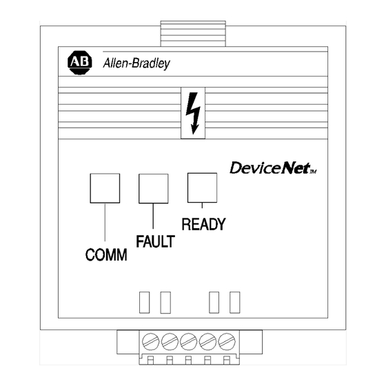
- Page 56 Chapter Troubleshooting The purpose of this chapter is to help you troubleshoot your DeviceNet Communication Module using the LEDs on the front of the device. Figure 7.1 Module Front View READY LED - Green when drive is powered up. FAULT LED - Red when drive is faulted Off when drive not faulted.
-
Page 57: Understanding The Comm Led
Troubleshooting ATTENTION: Do not attempt to defeat or override fault circuits. The cause of a fault indication must be determined and corrected before attempting operation. Failure to correct a drive or system malfunction may result in personal injury and/or equipment damage due to uncontrolled machine system operation. -
Page 58: Understanding The Fault Led
Troubleshooting Understanding the FAULT LED When the FAULT LED is Red, a drive fault is present. The Communi- cation Module uses two sets of fault codes depending on the setting of P15 - [Interface Select]. When P15 - [Interface Select] is set to a 0, the Bulletin 160 SSC interface, P7 - [Last Fault] uses the fault codes in Table 2. - Page 59 Troubleshooting Understanding the FAULT LED (Continued) Table 2: Bulletin 160 SSC Interface Fault Codes (Continued) Fault Fault Code Description Corrective Action Indication No DeviceNet 24 volt network power is not detected. Check DeviceNet connector at Communication Module. Power Also, check network’s power supply. DeviceNet Module DeviceNet Module EEPROM has invalid data.
- Page 60 Troubleshooting Understanding the FAULT LED (Continued) Table 3: ODVA Drive Profile Fault Codes (Continued) Fault Fault Code Description Corrective Action Indication 4310 Over Temperature Excessive heat detected. Clear blocked or dirty heat sink fins. Check ambient tem- perature. Check for blocked or non-operating fan. 5300 Drive Reset Stop input not present.
-
Page 61: Specifications
Appendix Specifications Electrical Network Supply Voltage 11 to 25 VDC Network Input Current 40 mA maximum Power Consumption 1 Watt maximum Environmental Ambient Temperature Operating 0 to 50° C (32 to 122° F) Storage -40 to 85° C (-40 to 185° F) Relative Humidity 0 to 95% non-condensing 1.0 G Operational... -
Page 62: Devicenet Information
Appendix DeviceNet Information The DeviceNet communication module allows a Bulletin 160 SSC drive to operate as a slave device on a DeviceNet network. The com- munication module supports Explicit Messages and Polled or Change of State/Cyclic I/O Messages of the predefined master/slave connec- tion set. -
Page 63: Object Classes
DeviceNet Information Object Classes The Communication Module supports the following object classes. Class Object Class Object 0x01 Identity 0x29 Control Supervisor 0x03 DeviceNet 0x2A AC Drive 0x04 Assembly 0xB3 160 Parameter Table 0x05 Connection 0xB4 DeviceNet Interface 0x28 Motor Data Publication 0160-5.5 - September 1997... -
Page 64: Class Code 0X01 - Identity Object
DeviceNet Information Class Code 0x01 — Class Attributes Identity Object Attribute ID Access Rule Name Data Type Value Revision UINT Max Instances UINT Max ID Class UINT Max ID Instance UINT Number of Instances: 2 Instance 1 Attributes: Drive Instance Attribute ID Access Rule Name... - Page 65 DeviceNet Information Class Code 0x01— Identity Object (Continued) Instance 2 Attributes: DeviceNet Instance (available with Communication Module version 2.00 and later) Attribute ID Access ID Name Data Type Value Vendor UINT Product Type UINT 105 = Subassembly Product Code UINT Revision Structure of Major...
-
Page 66: Class Code 0X03 - Devicenet Object
DeviceNet Information Class Code 0x03 — DeviceNet Object Class Attributes: None Supported Number of Instances: 1 Instance 1 Attributes: Attribute ID Access Rule Name Data Type Value Get/Set Node Address USINT 0 to 63 Get/Set Data Rate USINT 0 to 2 0 = Hold in error state on BOI error Get/Set BOOL... -
Page 67: Class Code 0X05 - Connection Object
DeviceNet Information Class Code 0x05 — Connection Object Class Attributes: None Supported Number of Instances: 3 Instance 1 Attributes: Explicit Message Instance Attribute ID Access Rule Name Data Type Value 0 = Nonexistant 1 = Configuring 3 = Established State USINT 4 = Timed out 5 = Deferred delete (available with Commu-... - Page 68 DeviceNet Information Class Code 0x05 — Connection Object (Continued) Instance 2: Attributes (Polled I/O Message Connection) Attribute ID Access Rule Name Data Type Value 0 = Nonexistant 1 = Configuring State USINT 3 = Established 4 = Timed out Instance Type USINT 1 = I/O Message Transport Class Trigger...
- Page 69 DeviceNet Information Class Code 0x05 — Connection Object (Continued) Instance 4 Attributes: Change of State/Cyclic Instance (Available with Communication Module version 2.00 and later) Attribute ID Access Rule Name Data Type Value 0 = Nonexistant 1 = Configuring State USINT 3 = Established 4 = Timed out Instance Type...
-
Page 70: Class Code 0X28 - Motor Data Object
DeviceNet Information Class Code 0x28 — Motor Data Object Class Attributes: None Supported Number of Instances: 1 Instance 1 Attributes Access Attribute ID Name Data Type Min/Max Units Default Description Rule Rated Stator Current Get/Set Rated Current UINT 0 to 100.00 0.01 Amps Drive Rating (from motor nameplate). -
Page 71: Class Code 0X29 - Control Supervisor Object
B-10 DeviceNet Information Class Code 0x29 — Control Supervisor Object Class Attributes: None Supported Number of Instances: 1 Instance 1 Attributes: Access Attribute ID Name Data Type Min/Max Default Description Rule Get/Set RunFwd BOOL 0 to 1 See page B-12. Get/Set RunRev BOOL... -
Page 72: State Transition Diagram
DeviceNet Information B-11 Class Code 0x29 — Common Services Control Supervisor Object Implemented for: (Continued) Service Service Code Name Class Instance 0x0E Get_Attribute_Single 0x10 Set_Attribute_Single State Transition Diagram The following State Transition Diagram provides a graphical descrip- tion of the states and state transitions that are reflected in attribute #6. Figure B.1 State Transition Diagram Non-Existent... -
Page 73: Run/Stop Event Matrix
B-12 DeviceNet Information Class Code 0x29 — Run/Stop Event Matrix Control Supervisor Object Attribute 5, NetCtrl is used to request that Run/Stop events be con- (Continued) trolled from the network. The following must occur before Run/Stop control is accomplished from the network: •... -
Page 74: Class Code 0X2A - Ac Drive Object
DeviceNet Information B-13 Class Code 0x2A — AC Drive Object Class Attributes: None Supported Number of Instances: 1 Instance 1 Attributes: Attribute Access Data Name Min/Max Units Default Description Rule Type AtReference BOOL 0 to 1 Set to 1 when SpeedActual is equal to SpeedRef. 1 = Drive uses SpeedRef (attribute 8) as its speed reference. -
Page 75: Class Code 0Xb3 — 160 Parameter Table Object
Temperature of the drive heatsink. [Drive Status] USINT Binary Number Status of drive in binary coded format. [Drive Type] UINT Numeric Value Used by Allen-Bradley field service personnel. [Control version] UINT Numeric Value version of drive firmware used. [Input Status] USINT Binary Number Open (0) Closed (1) state of drive’s discrete inputs. - Page 76 [Clear Fault] BOOL Numeric Value Setting to 1 performs a fault reset. Get/Set [Memory Probe Address] UINT Numeric Value Used by Allen-Bradley service personnel. Get/Set [Reset Defaults] USINT Numeric Value Sets all parameters to their factory default. Get/Set [Program Lock]...
- Page 77 B-16 DeviceNet Information Class Code 0xB3 — 160 Parameter Table Object (Continued) Access Data Attribute ID Parameter Name Units Description Rule Type Get/Set [Preset Frequency 3] UINT 0.1 Hz Sets command frequency when selected. Get/Set [Preset Frequency 4] UINT 0.1 Hz Sets command frequency when selected.
-
Page 78: Class Code 0Xb4 - Dn Interface Object
DeviceNet Information B-17 Class Code 0xB4 — DN Interface Object Class Attributes: None Supported Number of Instances: 1 Instance 1 Attributes: Access Data Attribute ID Name Min/Max Default Description Rule Type Zero USINT Returns zero. 0 = Bulletin 160 SSC Interface. Get/Set Interface Select USINT... -
Page 79: Class Code 0X04 - Assembly Objects
B-18 DeviceNet Information Class Code 0x04 — Assembly Objects Class Attributes: None Supported Number of Instances: 19 Instance 1 to 105 Attributes: I/O Instances (Available with Communication Modules version 2.00 and later) Access Attribute ID Name Data Type Min/Max Default Description Rule Data... -
Page 80: Instance Data Format
DeviceNet Information B-19 Instance Data Format Output Assemblies Instance 1 Data Format (Basic Contactor Output Assembly) Byte Bit 7 Bit 6 Bit 5 Bit 4 Bit 3 Bit 2 Bit 1 Bit 0 Instance 2 Data Format (Basic Overload Output Assembly) Byte Bit 7 Bit 6... - Page 81 (DN Preset Cmd contains these three bits) Preset 2 Preset 1 Preset 0 Instance 103 Allen-Bradley Drive Output Assembly (Available with Communication Module version 2.00 and later) This output assembly mirrors the 1305/1336 IO format. Byte Bit 7 Bit 6...
-
Page 82: Input Assemblies
DeviceNet Information B-21 Instance Data Format (Continued) Input Assemblies Instance 50 Data Format (Basic Overload/Contactor Input Assembly) Byte Bit 7 Bit 6 Bit 5 Bit 4 Bit 3 Bit 2 Bit 1 Bit 0 Faulted Instance 51 Data Format (Extended Overload/Contactor Input Assembly) Byte Bit 7 Bit 6... -
Page 83: Publication 0160-5.5 - September
Value of parameter pointed to by Parameter Number 27 (Low Byte) Value of parameter pointed to by Parameter Number 27 (High Byte) Instance 104: Allen-Bradley Input Assembly (Available with Communication Module version 2.00 and later) This input assembly mirrors the Bulletin 1305 I/O Format. - Page 84 Input Assemblies (Continued) Instance 105: Allen-Bradley Drive Input Assembly with Parameters (Available with Communication Module version 2.00 and later) 160 SSC parameter values are used to form the Output_Data structure for this assembly. Parameter 26 and 27 contain numbers of the display parameter values that form this assembly.
-
Page 85: Configuration Assembly Data Formats
B-24 DeviceNet Information Configuration Assembly Data Formats Instance 190 Data Format (Full Configuration Assembly – Series A – Signal Follower Model) Parameter Parameter Config Num. Description Size Config Num. Description Size Number Number Accel Time 1 DB enable Decel Time 1 S-Curve Minimum Frequency Memory Probe Address... - Page 86 DeviceNet Information B-25 Configuration Assembly Data Formats (Continued) Instance 190 Data Format (Full Configuration Assembly – Series A – Preset Speed Model) Parameter Parameter Config Num. Description Size Config Num. Description Size Number Number Accel Time 1 Preset Frequency 0 Decel Time 1 Preset Frequency 1 Minimum Frequency...
- Page 87 B-26 DeviceNet Information Configuration Assembly Data Formats (Continued) Instance 190 Data Format (Full Configuration Assembly – Series B - Signal Follower Model) Parameter Parameter Config Num. Description Size Config Num. Description Size Number Number Accel Time 1 Internal Frequency Decel Time 1 Frequency Select Minimum Frequency Zero Offset...
- Page 88 DeviceNet Information B-27 Configuration Assembly Data Formats (Continued) Instance 190 Data Format (Full Configuration Assembly – Series B Preset Model) Parameter Parameter Config Num. Description Size Config Num. Description Size Number Number Accel Time 1 Preset Frequency 0 Decel Time 1 Preset Frequency 1 Minimum Frequency Preset Frequency 2...
- Page 89 B-28 DeviceNet Information Configuration Assembly Data Formats (Continued) Instance 191 Data Format (Fixed Configuration Assembly – All Preset Speed Models) Parameter Parameter Config Num. Description Size Config Num. Description Size Number Number Accel Time 1 Output Configuration Decel Time 1 Output Threshold Minimum Frequency PWM frequency...
- Page 90 DeviceNet Information B-29 Configuration Assembly Data Formats (Continued) Instance 193 Data Format (Fixed Configuration Assembly – DeviceNet Module) Config Num. Parameter Number Description Size Interface Select Motor Base RPM DN Fault Mode Output Assembly Input Assembly Nonvolatile MAC ID Nonvolatile Baud Assembly Word 0 Assembly Word 1 Assembly Word 2...
- Page 91 B-30 DeviceNet Information Notes: Publication 0160-5.5 - September 1997...
-
Page 92: The Odva Interface
Appendix ODVA Interface Parameter Descriptions The ODVA Interface This appendix describes in detail the parameters that are defined in the ODVA Interface EDS files contained on the 160-EDS disk (Cat. No. 160-EDS). Important: This document describes the parameter set for a Series B Bulletin 160. - Page 93 ODVA Interface Parameter Descriptions ODVA Drive Profile Interface Parameters (Continued) Object Mapping Parameter Parameter Min./Max. Factory Name and Description (Class- Units Number Group Range Default Instance- Attribute) Motor [Motor Rated Current] 0x28-1-6 0 to 24.00 0.01 Drive This read/write parameter is set to the motor nameplate full load Amp rat- Amperes Amperes Rating...
- Page 94 ODVA Interface Parameter Descriptions ODVA Drive Profile Interface Parameters (Continued) Object Mapping Parameter Parameter Min./Max. Factory Name and Description (Class- Units Number Group Range Default Instance- Attribute) Control [Ready] 0x29-1-9 0 to 1 Numeric – Supervisor This read only parameter reflects the ready state of the drive. Value 1 = Drive State is Ready or Enabled.
- Page 95 ODVA Interface Parameter Descriptions ODVA Drive Profile Interface Parameters (Continued) Object Mapping Parameter Parameter Min./Max. Factory Name and Description (Class- Units Number Group Range Default Instance- Attribute) AC Drive [At Reference] 0x2A-1-3 0 to 1 Numeric – This read only parameter is set to 1 if the drive is at its speed reference. Value AC Drive [Network Reference]...
- Page 96 Numeric Numeric Extension This read only parameter contains the version of the drive firmware. Value Value Value Used by Allen-Bradley service personnel. AC Drive [Input Status] 0x2A-1-112 000000 to Binary – Extension This read only parameter contains the open (0) closed (1) state of the...
- Page 97 ODVA Interface Parameter Descriptions ODVA Drive Profile Interface Parameters (Continued) Object Mapping Parameter Parameter Min./Max. Factory Name and Description (Class- Units Number Group Range Default Instance- Attribute) AC Drive [Stop Mode Select] 0x2A-1-114 0 to 2 Numeric Extension This read/write parameter determines the stopping mode used by the Value drive when a stop is initiated.
- Page 98 ODVA Interface Parameter Descriptions ODVA Drive Profile Interface Parameters (Continued) Object Mapping Parameter Parameter Min./Max. Factory Name and Description (Class- Units Number Group Range Default Instance- Attribute) AC Drive [Input Mode] 0x2A-1-146 0 to 3 Extension This read/write parameter configures the TB3 control inputs for either 3-wire or 2-wire run forward/run reverse control.
- Page 99 ODVA Interface Parameter Descriptions ODVA Drive Profile Interface Parameters (Continued) Object Mapping Parameter Parameter Min./Max. Factory Name and Description (Class- Units Number Group Range Default Instance- Attribute) AC Drive [S-Curve] 0x2A-1-153 0 to 10 Numeric Extension This read/write parameter enables a fixed S-Curve acceleration/deceler- Value ation profile.
- Page 100 ODVA Interface Parameter Descriptions ODVA Drive Profile Interface Parameters (Continued) Object Mapping Parameter Parameter Min./Max. Factory Name and Description (Class- Units Number Group Range Default Instance- Attribute) DeviceNet [Bus Off Error] 0x03-1-3 0 to 1 Numeric Configura- This read/write parameter determines how the Communication Module Value tion processes a CAN Bus Off condition.
- Page 101 C-10 ODVA Interface Parameter Descriptions ODVA Drive Profile Interface Parameters (Continued) Object Mapping Parameter Parameter Min./Max. Factory Name and Description (Class- Units Number Group Range Default Instance- Attribute) Preset [DN Preset Cmd] 0x2A-1-192 0 to 7 Numeric This read/write parameter acts as the network preset command. Value Preset [Preset RPM 0]...
- Page 102 ODVA Interface Parameter Descriptions C-11 ODVA Drive Profile Interface Parameters (Continued) Object Mapping Parameter Parameter Min./Max. Factory Name and Description (Class- Units Number Group Range Default Instance- Attribute) AC Drive [IR Compensation] 0x2A-1-171 0 to 150 Extension Adds a voltage to the output based on the torque current. AC Drive [Slip Compensation] 0x2A-1-172 0.0 to 5.0...
- Page 103 C-12 ODVA Interface Parameter Descriptions ODVA Drive Profile Interface Parameters (Continued) Object Mapping Parameter Parameter Min./Max. Factory Name and Description (Class- Units Number Group Range Default Instance- Attribute) DeviceNet [Change of State Mask] 0xB4-1-13 0 to Numeric 0xFFFF Configura- This parameter, available with version 2.00 or later, is a 16 bit mask used 0xFFFF Value tion...
-
Page 104: Index
Index COMM LED factory default color 7-2 baud rate 3-5 description 7-2 data rate 3-5 state 7-2 fault troubleshooting 7-2 codes 7-4 communication module corrective action 7-4 installing 3-6, 3-8 description 7-4 powerup 4-1 fault codes removing 3-8 ODVA drive profile 7-4 configuration switches 3-3 getting started 2-1... - Page 105 Index modes of operation tools needed 2-1 error mode 4-2 troubleshooting 7-1 Powerup Reset 4-1 LEDs 7-1 run mode 4-2 module installation 3-1 understanding COMM LED 7-2 FAULT LED 7-3 powerup 4-1 powerup mode 4-1 procedures wiring quick start 2-1 DeviceNet connection 1-1, 3-7 quick start for experienced users 2-1...
- Page 106 DeviceNet and SSC are trademarks of Rockwell International.
- Page 107 Rico • Qatar • Romania • Russia-CIS • Saudi Arabia • Singapore • Slovakia • Slovenia • South Africa, Republic • Spain • Sweden • Switzerland • Taiwan • Thailand • Turkey • United Arab Emirates • United Kingdom • United States • Uruguay • Venezuela • Yugoslavia Allen-Bradley Headquarters, 1201 South Second Street, Milwaukee, WI 53204 USA, Tel: (1) 414 382-2000 Fax: (1) 414 382-4444 Publication 0160-5.5 – September 1997 PN 40055-164-02 (01) Supersedes Publication 0160-5.5 –...
Need help?
Do you have a question about the Bulletin 160 DeviceNet and is the answer not in the manual?
Questions and answers