
Related Manuals for Allen-Bradley 1794-OA8K


Summary of Contents for Allen-Bradley 1794-OA8K
-
Page 1: Table Of Contents
Installation Instructions FLEX I/O AC Digital Output Modules Catalog numbers 1794-OA8, 1794-OA8K, 1794-OA8I, 1794-OA16 Table of Contents Topic Page Important User Information Environment and Enclosure Preventing Electrostatic Discharge European Hazardous Location Approval North American Hazardous Location Approval Install Your FLEX I/O AC Digital Output Module... -
Page 2: Important User Information
2 FLEX I/O AC Digital Output Modules Important User Information Solid state equipment has operational characteristics differing from those of electromechanical equipment. Safety Guidelines for the Application, Installation and Maintenance of Solid State Controls (Publication SGI-1.1 available from your local Rockwell Automation sales office or online at http://www.rockwellautomation.com/literature/) describes some important differences between solid state equipment and hard-wired electromechanical devices. -
Page 3: Environment And Enclosure
FLEX I/O AC Digital Output Modules Environment and Enclosure ATTENTION: This equipment is intended for use in a Pollution Degree 2 industrial environment, in overvoltage Category II applications (as defined in EN/IEC 60664-1), at altitudes up to 2000 m (6562 ft) without derating. This equipment is not intended for use in residential environments and may not provide adequate protection to radio communication services in such environments. - Page 4 4 FLEX I/O AC Digital Output Modules ATTENTION: This product is grounded through the DIN rail to chassis ground. Use zinc plated chromate-passivated steel DIN rail to assure proper grounding. The use of other DIN rail materials (for example, aluminum or plastic) that can corrode, oxidize, or are poor conductors, can result in improper or intermittent grounding.
-
Page 5: European Hazardous Location Approval
Be sure that power is removed or the area is nonhazardous before proceeding. European Hazardous Location Approval Approved for the 1794-OA8K module only. The following applies to products marked II 3 G: Are Equipment Group II, Equipment Category 3, and comply with the Essential Health and Safety Requirements relating to the design and construction of such equipment given in Annex II to EU Directive 2014/34/EU. - Page 6 6 FLEX I/O AC Digital Output Modules WARNING: Observe the following additional certification requirements: • This equipment is not resistant to sunlight or other sources of UV radiation. • This equipment shall be mounted in an ATEX/IECEx Zone 2 certified enclosure with a minimum ingress protection rating of at least IP54 (in accordance with EN/IEC 60079-15) and used in an environment of not more than Pollution Degree 2 (as defined in EN/IEC 60664-1) when...
-
Page 7: North American Hazardous Location Approval
FLEX I/O AC Digital Output Modules North American Hazardous Location Approval The following modules are North American Hazardous Location approved: 1794-OA8, 1794-OA8K, 1794-OA8I, 1794-OA16. The following information applies when Informations sur l’utilisation de cet operating this equipment in hazardous équipement en environnements dangereux: locations: Products marked "CL I, DIV 2, GP A, B, C, D"... -
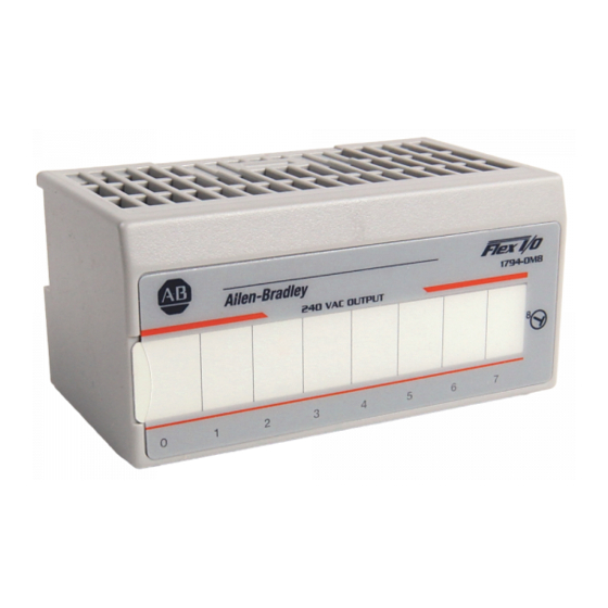
Page 8: Install Your Flex I/O Ac Digital Output Module
8 FLEX I/O AC Digital Output Modules Install Your FLEX I/O AC Digital Output Module 45284 Description Description Flexbus connector Groove Latching mechanism Alignment bar Keyswitch Module Terminal base The module mounts on a 1794 terminal base. WARNING: 1794-TBNF and 1794-TBNFK are not approved for Class I Division 2 Applications. - Page 9 34…51 row (C) for each output as indicated in the Wiring Connections for 1794-OA8 and 1794-OA8K table. The odd numbered terminals of row (C) are internally connected together to V AC L2 common.
- Page 10 10 FLEX I/O AC Digital Output Modules Wiring Connections for 1794-OA8 and 1794-OA8K 1794-TB2, 1794-TB3, 1794-TB3S 1794-TBN, 1794-TBNF Output Output Terminal Common Output Terminal Common Terminal (L2) Terminal (L2) A-1/B-17 A-3/B-19 A-5/B-21 A-7/B-23 A-9/B-25 A-10 A-11/B-27 B-10 C-11 A-12 A-13/B-29...
- Page 11 FLEX I/O AC Digital Output Modules 1794-TBN and 1794-TBNF Terminal Base Wiring for 1794-OA8 Even Numbered I/O Terminals 0…14 Odd Numbered I/O Terminals 1…15 Connect 120V AC (L2) to terminal B-16 Connect 120V AC power (L1) to terminal C-34 45672 Use B-33 and C-51 for daisychaining to the next terminal base Connect Wiring for the 1794-OA8I For 1794-TB2, 1794-TB3, or 1794-TB3S –...
- Page 12 12 FLEX I/O AC Digital Output Modules Wiring Connections for 1794-OA8I 1794-TB2, 1794-TB3, 1794-TB3S 1794-TBN, 1794-TBNF Output Output Terminal 120V AC Output 120V AC Supply Terminal Supply A-10 A-11 B-10 C-11 A-12 A-13 B-12 C-13 A-14 A-15 B-14 C-15 A = Even numbered terminals 0…14 for customer connections; corresponding odd numbered 120V AC supply L1 terminals 1…15 for customer connections from isolated power supply.
- Page 13 FLEX I/O AC Digital Output Modules 1794-TBN and 1794-TBNF Terminal Base Wiring for 1794-OA8I Even Numbered I/O Terminals 0...14 Odd Numbered I/O Terminals 1...15 Connect outputs to even numbered terminals on row (B). Connect isolated 120V AC (L1) to odd numbered terminals on row (C). Individual isolated 120V AC common (L2) must be run externally to each 45674 of the output devices.
- Page 14 14 FLEX I/O AC Digital Output Modules At the end of its life, this equipment should be collected separately from any unsorted municipal waste. Wiring Connections for 1794-OA16 Output 1794-TB2, 1794-TB3, 1794-TB3S 1794-TBN Channel Output Terminal 120V AC Common (L2) Output Terminal B-17 B-18...
-
Page 15: Configure The Flex I/O Ac Output Module
Connect 120V AC power (L1) to terminal C-34 Use B-33 and C-51 for daisychaining to the next terminal base 45676 Configure the FLEX I/O AC Output Module Image Table Memory Map for the 1794-OA8, 1794-OA8K, and 1794-OA8I Modules Read Not used – set to 0 Write Not used –... - Page 16 16 FLEX I/O AC Digital Output Modules Image Table Memory Map for the 1794-OA16 Module Read Not used – set to 0 Write Where O = Output number Publication 1794-IN103D-EN-P - July 2018...
-
Page 17: Specifications
On-state current, min 5.0 mA per output On-state current, max 500 mA per output @ 55 °C (sufficient to operate an Allen-Bradley Bulletin 500 NEMA size 3 motor starter) 750 mA per output @ 35 °C 1.0 A on 4 non-adjacent outputs, 500 mA on the remaining 4 outputs @ 30 °C... - Page 18 18 FLEX I/O AC Digital Output Modules Output signal delay is the time from receipt of an output on or off command to the output actually turning on or off. Module outputs are not fused. Fusing is recommended. If fusing is desired, you must supply external fusing or use the 1794-TBNF terminal base, if recommended.
- Page 19 109 g (3.84 oz) – 1794-OA8, 1794-OA8K 107 g (3.77 oz.) – 1794-OA8I 96 g (3.38 oz.) – 1794-OA16 Indicators (field side indication) 8 yellow status indicators – 1794-OA8, 1794-OA8K, 1794-OA8I 16 yellow status indicators – 1794-OA16 External AC power supply voltage 120V AC External AC power voltage range 85...132V AC –...
- Page 20 IEC 60068-2-2 (Test Bd, Operating Dry Heat), IEC 60068-2-14 (Test Nb, Operating Thermal Shock): -20…55 °C (-4…131 °F) – 1794-OA8, 1794-OA8K, 1794-OA8I 0 °C < Ta < +55 °C (+32 °F < Ta < +131 °F) – 1794-OA16 Temperature, surrounding air, 55 °C (131 °F)
- Page 21 UL Listed for Class I, Division 2 Group A,B,C,D Hazardous Locations, certified for U.S. and Canada. See UL File E334470. 1794-OA8, 1794-OA8K, 1794-OA8I CSA Certified Process Control Equipment. See CSA File LR54689C. CSA Certified Process Control Equipment for Class I, Division 2 Group A,B,C,D Hazardous Locations.
- Page 22 22 FLEX I/O AC Digital Output Modules Derating Curve for 1794-OA16 V in On-state oltage (V AC) Ambient Temperature o C The area within the curve represents the safe operating range for the module under various conditions of user supplied 120V AC supply voltages and ambient temperatures. = Normal mounting safe operating range.
- Page 23 FLEX I/O AC Digital Output Modules Notes: Publication 1794-IN103D-EN-P - July 2018...
- Page 24 RA-DU002, available at http://www.rockwellautomation.com/literature/. Allen-Bradley, Rockwell Automation, FLEX I/O, Rockwell Software and TechConnect are trademarks of Rockwell Automation, Inc. Trademarks not belonging to Rockwell Automation are property of their respective companies. Publication 1794-IN103D-EN-P - July 2018 Supersedes Publication 1794-IN103C-EN-P - July 2015 Copyright ©...
Need help?
Do you have a question about the 1794-OA8K and is the answer not in the manual?
Questions and answers