Table of Contents
Advertisement
Quick Links
Download this manual
See also:
User Manual
Advertisement
Table of Contents

Subscribe to Our Youtube Channel
Related Manuals for Omega zw Series


Summary of Contents for Omega zw Series
- Page 1 User’ s Guide Shop online at omega.com e-mail: info@omega.com For latest product manuals: www.omegamanual.info ZW-ED zw Series Wireless End Device...
- Page 2 Fax: (203) 359-7700 e-mail: info@omega.com For Other Locations Visit omega.com/worldwide The information contained in this document is believed to be correct, but OMEGA accepts no liability for any errors it contains, and reserves the right to alter specifications without notice.
-
Page 3: Table Of Contents
Table of Contents NOTES, WARNINGS AND CAUTIONS ........................3 PART 1: INTRODUCTION ............................4 EMC C AFETY AND ONSIDERATIONS ................................. ESD Warning ..............................4 EMC Considerations ............................4 EFORE EGIN ......................................Inspecting Your Shipment: ..........................4 Manuals / Software ............................4 ZW-REC ......................... - Page 4 Radio ................................. 20 CE ................................20 FCC / IC: ..............................20 FCC Radiation Exposure Statement: ......................20 P a g e...
-
Page 5: Notes, Warnings And Cautions
NOTES, WARNINGS and CAUTIONS Information that is especially important to note is identified by the following labels: • NOTE • WARNING or CAUTION • IMPORTANT • TIP NOTE: Provides you with information that is important to successfully setup and use the ZW-ED Wireless End Device. CAUTION or WARNING: Tells you about the risk of electrical shock. -
Page 6: Part 1: Introduction
If you need assistance, please contact the Customer Service Department n earest you. Manuals / Software: The latest User Manual as well as free software including iConnect and Omega Dashboard are available at the website listed on the cover page of this manual. P a g e... -
Page 7: Included With Your Zw-Rec
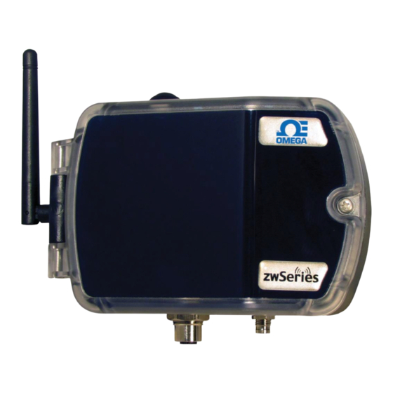
Included with Your ZW-REC Figure 1.1: ZW-ED Included Items • ZW-ED Wireless End Device • 2.4GHz Antenna • Mounting Kit including screws, anchors, mounting bracket and feet. • CR2032 Battery (Pre-Installed) • 2x C Cell Batteries P a g e... -
Page 8: Description
1028 total End Devices. For large networks the Omega Dashboard web server software can be used to allow the monitoring of devices connected to different receivers from a single webpage. -
Page 9: Part 2: Hardware
PART 2: HARDWARE ZW-ED Diagram Figure 2.1 – ZW-ED Diagram Table 2.1 – ZW-ED Diagram Power Button CR2032 Clock Backup Battery Transmit LED Serial Number Mounting Holes (x4) User Configuration Label C Cell Battery Holders 2.4GHz Antenna 5 – 36VDC / 24VAC Power Connector Hinge M12 Digital Probe Connector LCD (Optional) -
Page 10: Dip Switches
DIP Switches Figure 2.2 – ZW-ED DIP Switch Detail The ZW-ED has two banks of DIP switched located near the battery holder, inside of the unit, for easy configuration. Figure 2.2 shows a close up view of the switches. To change the DIP switches, use a tweezer or small screwdriver to gently push the switch. -
Page 11: Setting The Device Id
Setting the Device ID: The set of 8 switches, labeled Device ID in Figure 2.2, set the Device ID. The Device ID (or DID) uniquely identifies each ZW-ED to its Receiver. If there are multiple End Devices connected to a Receiver each one must have a unique DID. The ZW -ED supports Device IDs 0 to 127. - Page 12 Table 2.4 – Device ID (64 - 127) Switch Switch ON OFF OFF OFF ON OFF OFF OFF ON OFF ON OFF ON OFF ON OFF ON OFF ON OFF ON OFF OFF OFF ON OFF OFF OFF ON OFF ON OFF ON OFF ON OFF...
-
Page 13: Power Button
Power Button The Power Button is located on the top of the ZW -ED. (See Figure 2.1.) It allows for rebooting and shutting down the ZW-ED. You may need to reboot the ZW-ED to have it rejoin the network, if your Network ID, Device ID, Receiver, or Probe has changed, or if a different RF Frequency is selected. -
Page 14: Part 3: Initial Setup
Before powering up the ZW-ED ensure the supplied antenna is properly installed. Running the ZW-ED without an antenna, or with an unapproved antenna, may cause damage to the device and/or cause operation outside of regulatory compliance. Omega Engineering accepts no liability and issues no warranty for devices operated improperly. - Page 15 Table 3.1 – Compatible Probes Probe Sensor Smart Description Type Sensor zTP1-P Stick probe with 10’ Cable zTP2-P Lug Mount probe with 10’ Cable zTHP-P T, H 6” Industrial Probe with 10’ Cable Temperature / Humidity zTHP2-P T, H 3” Industrial Probe Temperature / Humidity zBTHP-P T, H, B...
-
Page 16: Powering The Unit
Powering the Unit Once the NID and DID are set and the Antenna and Probe are installed the ZW -ED may be powered on. The ZW-ED is powered using low cost Alkaline C cell batteries, the external M8 connector or both. The ZW-ED automatically switches from the internal batteries to the external power if available. -
Page 17: Line Power
Insert a new battery taking note of the proper orientation as shown in Figure 3.3. The positive battery terminal contacts the large terminal and faces towards the top of the ZW-ED. Line Power The ZW-ED may also be powered using line power. The Power Connector can accept 5V to 36V and 24V... -
Page 18: Part 4: Specifications
Environmental -18 to 55°C (0 to 130°F) 90% RH non-condensing NEMA 4 General Agency Approvals: ECCN 5A992, EMC 2014/30/EU LVD 2014/35/EU, RED 2014/53/EU Software: Compatible with the OMEGA Dashboard Battery Life Update Time Estimated Battery Life 10 Seconds 2.5 Years... -
Page 19: Appendix A: Rf Topics
APPENDIX A: RF Topics This section discusses some topics to ensure the best RF coverage range. RF Channel Selection The 802.15.4 wireless standard uses 16 RF channels numbered 11 through 26. Each channel has a bandwidth of 2MHz and channels are separated by 5MHz. When a ZW-ED is powered on it automatically searches for a Receiver with the same Network ID by scanning each RF channel. -
Page 20: Maximizing Range
Signal Strength vs Received Power -110 -100 Power [dBm] Figure A.2 – Received Power Chart Maximizing Range Under favorable conditions the ZW-ED can achieve a, line of sight, wireless link distance of up to 1000m. Generally, most indoor applications will not be able to achieve these distances, although steps can be taken to maximize range. -
Page 21: Appendix B: Wireless Certifications
APPENDIX B: Wireless Certifications Federal Communication Commission Interference Statement To comply with FCC radio frequencies (RF) exposure limits, dipole antennas should be located at a minimum 7.9" (200mm) or more from the body of all persons. This device complies with Part 15 of the FCC Rules. Operation is subject to the following two conditions: (1) This device may not cause harmful interference, and (2) this device must accept any interference received, including interference that may cause undesired operation. -
Page 22: Appendix C: Safety & Regulatory Compliance
APPENDIX C: SAFETY & REGULATORY COMPLIANCE Safety: EN 61010-1 3 Edition EMC: EN 61326-1:2013 Radio: EN 300 328 V1.8.1:2012-04 The product herewith complies with the essential requirements and other relevant provisions of the Radio Equipment Directive 2014/53/EU, the EMC Directive 2014/30/EU, and the Low Voltage Directive 2014/35/EU, and carries the CE -marking accordingly. - Page 23 Department will issue an Authorized Return (AR) number immediately upon phone or written request. Upon examination by OMEGA, if the unit is found to be defective, it will be repaired or replaced at no charge. OMEGA’s WARRANTY does not apply to defects resulting from any action of the purchaser, including but not limited to mishandling, improper interfacing, operation outside of design limits, improper repair, or unauthorized modification.
- Page 24 Where Do I Find Everything I Need for Process Measurement and Control? OMEGA…Of Course! Shop online at omega.com TEMPERATURE M U Thermocouple, RTD & Thermistor Probes, Connectors, Panels & Assemblies M U Wire: Thermocouple, RTD & Thermistor M U Calibrators & Ice Point References M U Recorders, Controllers &...
Need help?
Do you have a question about the zw Series and is the answer not in the manual?
Questions and answers