Advertisement
Description
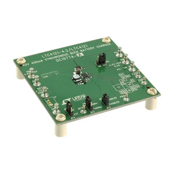
DC1977A-A
LTC4120EUD-4.2 (Fixed Output)
DC1977A-B
LTC4121EUD (Adjustable Output)
Demonstration Board DC1977A showcases the
LTC4121-4.2
and
LTC4121
buck battery charger integrated circuit. The DC1977A
supports the maximum-power-point tracking (MPPT)
feature of the LTC4121EUD to optimize power delivery
from photovotalic cells or highly resistive sources.
performance summary
SYMBOL
PARAMETER
IN
DC1977A Input Voltage
PV
DC1977A PV Cell Input
IN
V(BAT)
DC1977A BAT Pin Voltage
I(BAT)
DC1977A BAT Pin Current
Demo BoarD application
High Efficiency, Wide Input Voltage Range Charging with LTC4121
C
R
IN
RUN1
10µF
261k
R
R
RUN2
MPPT1
324k
787k
R
MPPT2
121k
V
+
IN
–
V
+ 200mV
BAT
TO 40V
R
PROG
3.01k
40V, 400mA synchronous-
Specifications are at T
CONDITIONS
Note: Reference designators refer to Schematic on p. 7.
I(IN) < 800mA
I(IN) < 800mA
R11 = 1.40MΩ, R12 = 1.05MΩ
V(BAT) = 3.7V; DC1977A; (R7) = 3.01kΩ; JP1 ("MPPT") = 'OFF'
INTV
IN
CC
BOOST
RUN
LTC4121
SW
MPPT
CHGSNS
BAT
FB
PROG
FREQ
GND
FBG
DC1977A-A/DC1977A-B
LTC4121EUD/LTC4121EUD-4.2
400mA Synchronous Buck
The LTC4121 and LTC4121-4.2 feature constant-current–
constant-voltage charging capability suitable for lithium-
ion or lead-acid cells. The LTC4121-4.2 supports charging
a single lithium-ion cell with a cell voltage of 4.2V. The
LTC4121 may be programmed to charge battery voltages
up to 18V with a resistive divider.
Design files for this circuit board are available at
http://www.linear.com/demo/DC1977
L, LT, LTC, LTM, Linear Technology and the Linear logo are registered trademarks of Analog
Devices, Inc. All other trademarks are the property of their respective owners.
= 25°C
A
C
INTVCC
2.2µF
C
BOOST
22nF
LPS4018-333ML
R
FB1
C
1.05M
BAT
47µF
R
FB2
+
1.40M
Li-Ion
dc1977a F01
DEMO MANUAL
Battery Charger
MIN
TYP
MAX
4.4
40
5
40.5
2.5
4.25
383
402
421
LTC4121 Efficiency vs V
100
R
PROG
R
PROG
95
90
85
80
75
V
= 4.1V
BAT
70
5
10
15
20
25
30
V
(V)
IN
UNITS
V
V
V
mA
IN
= 6.04k
= 3.01k
35
40
DC1977A F02
dc1977afb
1
Advertisement
Table of Contents

Subscribe to Our Youtube Channel
Related Manuals for Linear Technology DC1977A-A


Summary of Contents for Linear Technology DC1977A-A
- Page 1 LTC4121EUD to optimize power delivery http://www.linear.com/demo/DC1977 from photovotalic cells or highly resistive sources. L, LT, LTC, LTM, Linear Technology and the Linear logo are registered trademarks of Analog Devices, Inc. All other trademarks are the property of their respective owners. performance summary Specifications are at T = 25°C...
- Page 2 DEMO MANUAL DC1977A-A/DC1977A-B assemBly test proceDure Refer to Figure 1 for the proper measurement equipment 5. Verify that VM1 indicates 3.3V to 3.9V, and then verify setup and jumper settings and follow the procedure below. that AM1 indicates 387mA to 417mA. Verify that VM2 shows 12.6V to 13.2.
-
Page 3: Theory Of Operation
DEMO MANUAL DC1977A-A/DC1977A-B theory of operation The LTC4121EUD-4.2/LTC4121EUD is a 4.4V ~ 40V input The buck regulator acts as a current source when the buck topology battery charger with maximum power point battery is in the constant-current charging region and as... - Page 4 DEMO MANUAL DC1977A-A/DC1977A-B theory of operation resistive power supplies. The MPPT pin allows program- ming of the MPPT point as a percentage of the open- circuit V ). To access this functionality the demo board provides JP1, the “MPPT” jumper, and R1 and R2.
- Page 5 DEMO MANUAL DC1977A-A/DC1977A-B theory of operation Battery capacitors C1 and C2 The maximum battery voltage for the LTC4121EUD is 18V, and for the LTC4121EUD-4.2, it is 4.2V. Analog Devices recommends 47µF of capacitance on the BAT pin, if the battery is not present. For the LTC4121EUD the voltage rating of the capacitor will need to be 25V, so two 22µF, 25V, MLCC capacitors are used.
-
Page 6: Parts List
JP1-JP4 SHUNT, 2mm SAMTEC, 2SN-BK-G ITEM REFERENCE PART DESCRIPTION MANUFACTURER/PART NUMBER DC1977A-A Bill of Materials Required Circuit Components DO NOT INSTALL RES, CHIP , 0Ω jumper, 1/16W, 0402 VISHAY, CRCW04020000Z0E 40V 400mA SYNCHRONOUS STEP-DOWN BATTERY LINEAR TECH., LTC4121EUD-4.2#PBF CHARGER, 3mm × 3mmQFN16 CAP , CHIP , X5R, 47µF, ±10%, 16V, 1210... - Page 7 Information furnished by Linear Technology Corporation is believed to be accurate and reliable. However, no responsibility is assumed for its use. Linear Technology Corporation makes no representa- tion that the interconnection of its circuits as described herein will not infringe on existing patent rights.
- Page 8 Linear Technology Corporation (LTC) provides the enclosed product(s) under the following AS IS conditions: This demonstration board (DEMO BOARD) kit being sold or provided by Linear Technology is intended for use for ENGINEERING DEVELOPMENT OR EVALUATION PURPOSES ONLY and is not provided by LTC for commercial use. As such, the DEMO BOARD herein may not be complete in terms of required design-, marketing-, and/or manufacturing-related protective considerations, including but not limited to product safety measures typically found in finished commercial goods.
Need help?
Do you have a question about the DC1977A-A and is the answer not in the manual?
Questions and answers