
Related Manuals for Polaris Alpha


Summary of Contents for Polaris Alpha
- Page 1 ALPHA RTK RECEIVER USER GUIDE Version 0.8 October 25, 2018 info@polaris-gnss.com https://www.polaris-gnss.com...
-
Page 2: Table Of Contents
4-4 Hardware Configuration Settings ..............16 Preparing for First Time Use ................17 5-1 RTK Viewer ..................... 17 5-2 USB Driver ...................... 17 5-3 Checking Alpha Receives Satellite Signal ............17 RTK Setup ......................19 6-1 Introduction ....................19 6-2 Configuring the Rover ..................20 6-3 Configuring the Base .................. -
Page 3: Overview
RTK base, and provide centimeter-level accurate position result relative to the RTK base in standard NMEA message format. Alpha can also be configured as a RTK base to provide RTCM3.x message or SkyTraq carrier phase raw measurement data output. -
Page 4: Alpha Rtk Receiver Features
1-3 Alpha RTK Receiver Features Base or Rover Mode Configurable Using RTK Viewer Utility Supports L1 GPS/GLONASS or L1 GPS + B1 BDS RTK Operation Supports LV-TTL UART / USB / Bluetooth V2.1+EDR Interface Supports SDHC micro-SD Card for Data Logging Post Processing ... -
Page 5: Applications
GNSS signals and differential principles to achieve centimeter-level accuracy positioning with respect to the RTK base. Referring to figure 2-1, Alpha RTK base antenna is set at a fixed location, with antenna location coordinates already a known reference, or surveyed by method described in later section. It receives signals from GPS/GLONASS or GPS/BDS satellites, generates correction data in RTCM3.x or SkyTraq... -
Page 6: Description Of Interfaces
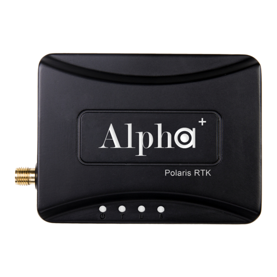
SMA connector for RTK antenna. Description Status LED. There are three states shown for Alpha as Rover Base data not received: flashes two times followed by 1 sec of silence. In process of finding RTK solution: flashes with frequency at 1Hz or 4 Hz depends on the RTK ratio is in between 1 and 3 or in between 3 and 5. -
Page 7: Pinout Of 6-Pin Connector
The red spot indicates the top side. Voltage Description Power input to Alpha when USB connector power unconnected 3.3V 5.5V Power output from Alpha if USB connector power is connected 4.6V 5.0V UART input for base data, RTCM3.x or SkyTraq raw 3.0V 3.6V... -
Page 8: Connector Cables For Alpha
Table 3-3 3-4 Connector Cables for Alpha There are several types of connector cable supplied with the Alpha RTK Kit for different applications. 3-4-1 Wire for connecting Base-to-Rover (for base/rover pair short baseline testing) Black Yellow White 6-pin Connector 6-pin Connector... - Page 9 3-4-4 Wire for 6-pin TTL connector with pitch 2.54 Dupont Lines Black Black Blue Blue Green Green Yellow White Yellow 6-pin Connector White 2.54 Dupont Female Connector Figure 3-7 3-4-5 Wire for 4-pin TTL connector with pitch 2.54 Dupont Lines Black Black Green...
-
Page 10: Application Scenarios
For users setting up a local RTK base for use with RTK rover, this experimental setup allows quickly becoming acquainted with all aspects of Alpha RTK receiver operation. Using our RTK Viewer Windows-PC software, users can configure Alpha to be base or rover; see section 6 for details. -
Page 11: Rtk Survey And Data Collection
Virtual Reference Station (VRS) service as shown in figure 4-3 for RTK survey and data collection, then only one Alpha RTK receiver is needed. It’s configured as RTK rover and connects to an Android smartphone via Bluetooth. User can then run the free Lefebure NTRIP Client App on the... - Page 12 Bluetooth to an Android smartphone. User can run the free Lefebure NTRIP Client App on the smartphone to retrieve the Alpha RTK base data over Internet and sending it to the Alpha RTK rover. With “MOCK Location” option enabled on the smartphone, the GPS related location...
-
Page 13: Real-Time Precision Guidance
UAV. A second Alpha is configured as RTK rover, connecting to the autopilot of the UAV via a 6-pin 6 wire cable provided along with the Alpha RTK Kit. In this application scenario data from RTK base is encapsulated in MAVLink injection protocol sent to autopilot of the UAV, and autopilot then relays the data to RTK rover, the NMEA message output from RTK rover is sent to autopilot of the UAV for precision guidance. - Page 14 For line-of-sight precision guidance applications that do not use Mission Planner with MAVLink protocol as in figure 4-6, user can configure one Alpha RTK receiver as RTK base and use 6-pin UART connector port or micro-USB port to connect to a telemetry radio for sending correction data to the RTK rover.
- Page 15 4-7. In this case user can setup an Alpha RTK base as described previously with figure-4-4, and with Alpha RTK rover also connecting pin-3 of the 6-pin connector to the real-time controller’s UART input for...
-
Page 16: Hardware Configuration Settings
4-4 Hardware Configuration Settings Table 4-1 shows push button and slide switch configuration settings for Alpha RTK receiver in different application scenarios. For each usage scenario, indicates which of the TTL / USB / Bluetooth interface should be selected to have Alpha’s LED light up, indicates which position to put Alpha’s slide switch. -
Page 17: Preparing For First Time Use
Connect antenna to the Alpha SMA connector and place antenna at a window side having good sky view. Put Alpha’s slide switch to A position. Open RTK Viewer. Connect Alpha to PC using micro-USB cable. A dialog box for COM port and baud rate will appear. Click “Connect”. Figure 5-1 ... - Page 18 Figure 5-2 Tip: if not sure which COM port is used by Alpha, can use Windows “Device Manager” to find out. Figure 5-3...
-
Page 19: Rtk Setup
Client that connects with RTK base station over Internet. Alpha can work with popular Trimble and Leica base stations. For base/rover pair usage, the applications could be: (1) an Alpha RTK receiver setup as local RTK base at some known reference location to serve other Alpha RTK receiver rovers within 10Km distance, (2) An Alpha RTK receiver first connecting to RTK base station service to determine its position accurately then later setup as local RTK base to serve other Alpha RTK receiver rovers within 10Km distance. -
Page 20: Configuring The Rover
6-2 Configuring the Rover To configure Alpha as RTK rover, put slide switch to position A, connect micro-USB cable to Alpha and a Windows PC running RTK Viewer. From the “Settings” pull-down menu on RTK Viewer select “Configure RTK Mode”. On the dialog box select “Configure as Rover” and press “Next” button. -
Page 21: Configuring The Base
6-3 Configuring the Base To configure Alpha as RTK base, put slide switch to position A, setup base antenna at location having unblocked sky view, connect antenna to Alpha using RF cable, connect Alpha to a Windows PC running RTK Viewer using micro-USB cable. From the “Settings” pull-down menu on RTK Viewer select “Configure RTK Mode”. - Page 22 On the next dialog box, there are 4 ways to configure the base antenna position: Figure 6-5 6-3-1 Input Fixed Base Antenna Coordinate When a reference point with known coordinate is available to setup the RTK base antenna, this option is to be selected.
- Page 23 Set Receiver to Self-Survey Approx. Coordinate for 60sec Each Time Powering Up With this setting, every time Alpha is powered up it’ll use the averaged position of initial 60 position fix for base antenna position reporting. This may be useful for RTK testing situations where position of the base will be moved from time to time, and rover’s centimeter-level accuracy relative-positioning...
- Page 24 This prepares Alpha RTK receiver as 3 -party base station connected RTK rover, able to determine its position to centimeter-level accuracy. Have a USB cable connecting Alpha and RTK Viewer, we can now select this 4 option to setup the Alpha RTK base antenna position. RTK Viewer will take 60 RTK Fix position averaged value to set permanent base antenna coordinate.
-
Page 25: Rtk Application Scenarios In Detail
6-pin 3 wire for Base-to-Rover (sec. 3-4-1) Figure 6-10 Configure one Alpha as rover (cf. section 6-2). Configure the other Alpha as a base with option "Set Receiver to Self-Survey Approx. Coordinate for 60sec Each Time Powering Up" (cf. section 6-3-2) - Page 26 6-pin TTL connector port. Use the supplied Base-to-Rover connector cable to connect Alpha RTK base and Alpha RTK rover. The USB cable connecting to the laptop supplies power and is also used for monitoring using RTK Viewer.
- Page 27 Start” button restarts the receiver without clearing internal data. 6-4-2 Connecting to 3 Party Base Using Phone . . . Setup for GIS Data Collection antenna NTRIP Rover client Bluetooth Alpha RTK Party RTK Base BT mode / switch on B Internet 3G/4G/LTE with NTRIP caster Figure 6-13...
- Page 28 Use section 6-2 method to configure Alpha into RTK rover. Figure 6-14 Once Alpha RTK rover setting is configured, use below steps to prepare for connecting to 3 party RTK base station: 1. Mount the rover antenna on a range pole or tripod.
- Page 29 7. Install Lefebure NTRIP Client from Google Play Store, open it. 8. Select the gear setup icon on the upper right corner. Select “Receiver Settings”.
- Page 30 9. For “Receiver Connection” select “External via Bluetooth”. For “Bluetooth Device” select the “BT SPP xxxxxx” device. Check “GPS Mock Locations”. 10. Select “NTRIP Settings”. Network Protocol select “NTRIP v1.0”. Enter base station and account information for Caster IP / Caster Port / Username / Password / Data Stream. Report Location select “Get From External Receiver”.
- Page 31 11. Enable phone’s Mobile Data connection. Select the gear icon on upper right to enter phone Settings configuration page. 12. Select “Developer Options” near the bottom of Settings page. Sliding down Developer Options page, select “Mock Location App”.
- Page 32 13. Select “Lefebure NTRIP Client”. 14. Return to Lefebure NTRIP Client App, click “Connect” to connect with Alpha RTK receiver via Bluetooth and RTK base station via Internet.
- Page 33 15. After connection is made, upper left screen will first show Invalid, denoting receiver does not have position fix yet. Next it’ll show GPS or DGPS and number of satellites used, denoting receiver has meter-level accuracy position fix. Then it’ll show FloatRTK for some time, denoting the receiver is trying to converge to centimeter-level accuracy position.
- Page 34 RTK base as described in section 6-3. Once Alpha RTK base and rover settings are properly configured and able to get rover RTK Fix with short baseline experiment as described in section 6-4-1, one can proceed to setup base to send data over Internet.
- Page 35 RTK base as described in section 6-3. Once Alpha RTK base and rover settings are properly configured and able to get rover RTK Fix with short baseline experiment as described in section 6-4-1, one can proceed to setup base/rover for UAV...
- Page 36 Mission Planner data. Items needed for building a complete RTK system are shown below. Figure 6-17 Since Mission Planner expects RTCM format base data, user must configure the Alpha RTK base to output in RTCM as described in section 6-3-5.
- Page 37 Select the 【RTK/GPS Inject】 icon on left panel of GUI. Select the COM port on which Alpha RTK base is assigned for the USB connection. Select 115200 baud rate that Alpha RTK base output RTCM data to Mission Planner.
- Page 38 Select 【Flight Data】 icon on the top menu bar to return to main page, Mission Planner will show current GPS status in below red rectangle enclosed area, and user could check and see if it’s working correctly. GPS: RTK Fixed GPS Status = 6.00 GPS: RTK Float GPS Status = 5.00...
- Page 39 USB/TTL mode / switch on A Figure 6-20 Use section 6-2 method to configure one Alpha receiver into RTK rover. Depending on what’s available to determine base antenna position, select one of the options to configure the second Alpha RTK receiver into RTK base as described in section 6-3.
- Page 40 Figure 6-21 Use section 6-2 method to configure one Alpha receiver into RTK rover. Depending on what’s available to determine base antenna position, select one of the options to configure the second Alpha RTK receiver into RTK base as described in section 6-3.
-
Page 41: Configure Rtk License
When Usage Plan is purchased, an email will be received by the customer requesting information on (1) Alpha Serial Number (2) Activation Start Date if One Year Usage Plan is purchased. To check the Alpha Serial Number, from RTK Viewer’s Viewer pull-down menu select “Configure RTK License”, click “Copy Serial Number”... -
Page 42: Raw Measurement Recording And Post Processing
For post-processing, both base data and rover data need to be available. The base data can be (1) stored RTCM data received from RTK base station service or (2) stored SkyTraq raw measurement data from Alpha RTK base. The RTK rover data is stored SkyTraq raw measurement data from Alpha RTK rover. -
Page 43: Software Update
Figure 9-1 9-2 Alpha RTK Receiver Software Update Before checking if new update software for Alpha is available, make sure Alpha is connected to RTK Viewer. From RTK Viewer “Updates” pull-down menu, select “Check Firmware Update”, then a message box showing “checking for updates” will pop up. - Page 44 Figure 9-2 If no new update is available, RTK Viewer will notify already running latest software. Figure 9-3 In case new update software is found, a dialog box will appear. Press “Yes” to update, or “No” to cancel update. Figure 9-4...
- Page 45 Alpha, RTK Viewer will show below message box indicating software update status. Figure 9-5 When software update is in progress, DO NOT remove the USB cable, or press Alpha’s push button, or change position of the slide switch until seeing software update is completed.
-
Page 46: Appendix
Figure A-1-1 Base data input baud rate of Alpha RTK rover is fixed at 115200. Sending base data to rover at incorrect baud rate will cause the rover unable to receive base data and never enter Float RTK state. - Page 47 A-1-2. Configure Update Rate Alpha supports 1 / 2 / 4 / 5 / 8 / 10 Hz RTK update rate; default is 1Hz. Higher update rate can be useful for precision guidance applications. Update rate command affects $GGA / $RMC / $VTG / $PSTI 030 messages;...
-
Page 48: A-2. Ntrip Server/Caster Setup For Users Without Fixed Ip
A-2. NTRIP Server/Caster Setup for Users Without Fixed IP Polaris offers a very low-cost subscription service that allows customers without fixed IP to setup RTK base station using open-source RTKLIB’s STRSVR to stream the base data to a re-directing server. The Lefebure NTRIP Client running on customer’s Android phone can then connect to the re-directing... - Page 49 Configure the input stream options as follows. Press the OK button to return to the STRSVR dialog when finished. Field Description Example Port Select the COM port for base data input COM7 Bitrate (bps) Serial port data input bit rate. 115200 Byte Size Byte Size depends on serial settings.
- Page 50 Set the output stream options as follows. Press the OK button to return to the STRSVR dialog when finished. The red color NTRIP Caster Host IP and Port Number are provided by Polaris to Base Data Redirecting Service subscription customers. The blue color Mountpoint and password are specified by customer at time of subscription application.
-
Page 51: A-3. Ntrip Server/Caster Setup For Users With Fixed Ip
Since the newest version RTKLIB v.2.4.3 provided on official website is in source code format and compilation required Borland™ C++ builder, a pre-compiled binary executable is made available at: https://www.polaris-gnss.com/strsvr.zip. After downloading, unzip it, “strsvr 2.4.3.exe” can be executed directly. - Page 52 Field Description Example Port Select the COM port for base data input COM5 Bitrate (bps) Serial port data input bit rate. 115200 Byte Size Byte Size depends on serial settings. 8 bits Parity Parity depends on serial settings. None Stop Bits Stop Bits depends on serial settings.
- Page 53 5. Press the Start button on the STRSVR panel to start the service and wait for the connection. Figure A-3-4 6. After remote NTRIP Client making connection, user should see the screen like following image. The green square flashes when there is ongoing data transmission and how many bytes have been transmitted is also shown on screen.
-
Page 54: A-4. Data Flow Of The I/O Interface
A-4 Data Flow of the I/O Interface There are 3 types of I/O interface, Bluetooth / USB / LV-TTL UART, on the Alpha RTK receiver for output of NMEA or base data, receiving base data, and receiving configuration command. The following figures provide a clear view for all 6 operation modes specified by the three interface selection LEDs and the two slide switch positions. - Page 55 Base Data Alpha Polaris RTK Command from RTK Viewer Base Data switch Figure A-4-4 Alpha Polaris RTK Command from RTK Viewer Base Data switch Figure A-4-5 Alpha Polaris RTK Command from RTK Viewer Base Data switch Figure A-4-6...
- Page 56 The information provided is believed to be accurate and reliable. These materials are provided to customers and may be used for informational purposes only. No responsibility is assumed for errors or omissions in these materials, or for its use. Changes to specification can occur at any time without notice.
Need help?
Do you have a question about the Alpha and is the answer not in the manual?
Questions and answers