
Related Manuals for Allen-Bradley 1756-ENET/B


Summary of Contents for Allen-Bradley 1756-ENET/B
- Page 1 ControlLogix Ethernet Communication Interface Module 1756-ENET/B User Manual AB PLCs...
- Page 2 Since there are many variables and requirements associated with any particular installation, Allen-Bradley does not assume responsibility or liability (to include intellectual property liability) for actual use based upon the examples shown in this publication.
- Page 3 Identifies information that is critical for successful IMPORTANT application and understanding of the product. Allen-Bradley and ControlLogix are trademarks of Rockwell Automation. Ethernet is a trademark of Digital Equipment Corporation, Intel, and Xerox Corporation. RSLinx and RSLogix 5000 are trademarks of Rockwell Software.
- Page 4 Voltage, by applying the safety requirements of EN 61131-2 Programmable Controllers, Part 2 - Equipment Requirements and Tests. For specific information required by EN 61131-2, see the appropriate sections in this publication, as well as the Allen-Bradley publication Industrial Automation Wiring and Grounding Guidelines, publication 1770-4.1.
- Page 5 Rockwell Automation Rockwell Automation offers support services worldwide, with over 75 sales/support offices, 512 authorized distributors and 260 authorized Support systems integrators located throughout the United States alone, as well as Rockwell Automation representatives in every major country in the world.
- Page 7 This manual is intended for control engineers and technicians who are installing, programming, and maintaining a control system that This Manual communicates on an Ethernet network through a 1756-ENET/B module. We assume you have a good understanding of Ethernet and the (TCP/IP) protocol.
- Page 8 Pictures of keys represent the actual keys you press. How To Use This Manual This manual provides an overview of the 1756-ENET/B module, as well as general information about Ethernet. It describes how to install and configure the module, and provides three example applications showing how to use the module to communicate over Ethernet.
- Page 9 • Produced and Consumed tags (chapter 7) Here’s an example of the type of system you’ll be creating for I/O applications: Slot 0 1 Slot 0 1 2 3 Local Remote Data Chassis Chassis 1756-ENET/B 1756-ENET/B 1756-OF8 Logix5550 130.130.130.2 130.130.130.3 Analog Output Controller Switch 1756-OB16I Digital Output 130.130.130.1...
- Page 10 Quantity Product Name Catalog Number Hardware ControlLogix chassis 1756-A4, (or -A7, -A13, -A13, -A17) ControlLogix power supply 1756-PA72, (or -PB72) Ethernet Communications Interface Module 1756-ENET/B Logix5550 controller 1756-L1 Analog Output Module 1756-OF8 Digital Input Module 1756-IB16I Digital Output Module 1756-0B16I...
- Page 11 Publication number Using Ethernet for Industrial Control Ethernet/IP Performance and Application Guide ENET-AP001A-EN-P Ethernet Media Ethernet/IP Cable Planning and Installation Guide ENET-IN001A-EN-P 1756-ENET/B module ControlLogix Ethernet Communication Module Installation 1756-IN015B-EN-P Instructions ControlLogix Chassis ControlLogix Chassis Installation instructions 1756-5.69 (Series A) 1756-5.80 (Series B)
- Page 12 About This User Manual Terminology This term Means bandwidth The transmission capacity of the network, expressed in bits per second. Traditional Ethernet has a 10Mbit bandwidth. Fast Ethernet is 100Mbit. BootP BootP (Bootstrap Protocol) is a low-level protocol that provides configurations to other nodes on a TCP/IP network.
- Page 13 About This User Manual This term Means Ethernet network A local area network designed for the high-speed exchange of information between computers and related devices. Ethernet/IP applies a common Ethernet Industrial Protocol. Ethernet/IP application layer (CIP) over Ethernet by encapsulating messages in TCP/UDP/IP.
- Page 14 About This User Manual This term Means IP address 32-bit identification number for each node on an Internet Protocol network. These addresses are represented as four sets of 8-bit numbers (numbers from 0 to 255), with periods between them. Each node on the network must have a unique IP address. latency The time between initiating a request for data and the beginning of the actual data transfer.
-
Page 15: Table Of Contents
Table of Contents Chapter 1 About the 1756-ENET/B Module What This Chapter Contains ......1-1 Module Features. - Page 16 Table of Contents Chapter 4 Configuring the Ethernet Module What This Chapter Contains ......4-1 Using the Rockwell BootP Utility .
- Page 17 Configuring the AB_ETH Driver ..... . . C-2 Appendix D 1756-ENET/B Support of Using the 1756-ENET/B Module in a ControlLogix Gateway . . D-1 ControlLogix Gateway Communication...
- Page 18 Table of Contents Publication 1756-UM051B-EN-P - November 2000...
-
Page 19: What This Chapter Contains
About the 1756-ENET/B Module What This Chapter Contains This chapter provides an overview of the ControlLogix 1756-ENET/B module, its primary features, what it does, and how to use it. You will need to understand the concepts discussed in this chapter in order to configure your Ethernet module and use it in a control system. -
Page 20: Hardware/Software Compatibility
About the 1756-ENET/B Module Hardware/Software The 1756-ENET/B module is compatible with the following firmware versions and software releases. Contact Rockwell Automation if you Compatibility need software or firmware upgrades to use this equipment.: Product Firmware Version/ Software Release 1756-ENET/B module 2.01 or higher... -
Page 21: Mixing Rack Optimized And Direct Connections
I/O modules set up to use Rack Optimization will communicate at the rate of the RPI (requested packet interval) configured for the 1756-ENET/B module. I/O modules configured for direct communication will communicate at their set RPI and ignore the Ethernet module’s RPI. -
Page 22: Use Of The Control And Information Protocol (Cip)
About the 1756-ENET/B Module Use of the Control and The Ethernet module uses the Control and Information Protocol (CIP). CIP is the application layer protocol specified for Ethernet/IP, the Information Protocol (CIP) Ethernet Industrial Protocol, as well as for ControlNet and DeviceNet. -
Page 23: Specifying The Requested Packet Interval (Rpi)
I/O module. RPIs are only used for modules that produce data. For example a local 1756-ENET/B module (i.e., an ENET/B module in the same chassis as the controller) does not require an RPI because it is not a data-producing member of the system;... - Page 24 About the 1756-ENET/B Module Publication 1756-UM051B-EN-P - November 2000...
-
Page 25: Installing The Ethernet Module
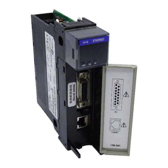
Wiring the Ethernet Connector Connecting the Module to the Ethernet Network Applying Chassis Power Checking Power Supply and Module Status Identifying Module Use the following illustration to identify the external features of the 1756-ENET/B module. Features Backplane Product Connector Label <... -
Page 26: Insertion And Removal Under Power
Installing the Ethernet Module Insertion and Removal The Ethernet module is designed to be installed or removed while chassis power is applied. However, please observe the following Under Power precautions. When you insert or remove the module while WARNING backplane power is on, or you connect or disconnect the communications connectors, an electrical arc can occur. -
Page 27: Determining Module Slot Location
Installing the Ethernet Module Determining Module Slot Location You can install the module in any slot in the ControlLogix chassis. You can also install multiple ENET/B modules in the same chassis. The figure below shows chassis slot numbering in a 4-slot chassis. In a ControlLogix chassis slot 0 is the first slot and is always the leftmost slot in the rack (the first slot to the right of the power supply). -
Page 28: Inserting The Module In The Chassis
Installing the Ethernet Module Inserting the Module in the Chassis Align the circuit board with top and bottom guides in the chassis. Circuit Board Slide the module into the chassis. Make sure the module backplane connector properly connects to the chassis backplane. -
Page 29: Removing Or Replacing The Module (When Applicable)
Installing the Ethernet Module Removing or Replacing the Module (when applicable) Push on upper and lower module tabs to disengage them. Slide module out of chassis. If you are replacing an existing module with an IMPORTANT identical one, and you want to resume identical system operation, you must install the new module in the same slot. -
Page 30: Wiring The Ethernet Connector
Installing the Ethernet Module Wiring the Ethernet Connector Use either an AUI or an RJ45 connector to connect to the Ethernet Note: If your application requires the module door to be closed, use one of the custom AUI network. Wire the appropriate connector as shown below: connector cables, available in two lengths: •... -
Page 31: Applying Chassis Power
Installing the Ethernet Module Attach either the AUI or RJ45 connector to the matching Ethernet port. POWER POWER Connecting the module to the network via an IMPORTANT Ethernet switch instead of a hub reduces the number of collisions and lost packets and increases the bandwidth. -
Page 32: Checking Power Supply And Module Status
Installing the Ethernet Module Checking Power Supply and Module Status Check the LED indicators to determine if the power supply and the Ethernet module are operating properly. < > ETHERNET POWER OK indicator is RED, then FLASHING RED (or is GREEN if module Power Supply indicator is configured). -
Page 33: Before You Configure Your Module
(TCP) and a network-layer protocol (IP) commonly used in business environments for communication within networks and across internetworks. The 1756-ENET/B module uses TCP/IP for “explicit” messaging, that is, messages in which time is not a critical factor, such as uploading or downloading programs. -
Page 34: User Datagram Protocol (Udp)
UDP is used by applications that implement their own handshaking between devices and only want a minimal transport service. UDP is smaller, simpler, and faster than TCP and can operate in unicast, multicast, or broadcast mode. The 1756-ENET/B module employs UDP for real time I/O messaging. Ethernet/IP Ethernet/IP applies a common application layer over Ethernet by encapsulating messages in TCP/UDP/IP. -
Page 35: Ip Address
Before You Configure Your Module Configuration Before you can use your Ethernet module, you must configure its IP address, gateway address, and subnet mask. The module ships with Requirements the Rockwell BootP utility, which you can use to perform the configuration. -
Page 36: Gateways
Before You Configure Your Module Contact your network administrator or the Network Information Center for a unique fixed IP address to assign to your module. For more information on Internet addressing, see Comer, Douglas E; Internetworking with TCP-IP, Volume 1: Protocols and Architecture; Englewood Cliffs, N.J.: Prentice-Hall, 1990. -
Page 37: Subnet Masks
Before You Configure Your Module Subnet Mask Subnet addressing is an extension of the IP address scheme that allows a site to use a single net ID for multiple physical networks. Routing outside of the site continues by dividing the IP address into a net ID and a host ID via the class. -
Page 38: For More Information
Before You Configure Your Module For More Information For more information about Ethernet, refer to the following publications: • Internetworking with TCP/IP ISBN 0-13-216987-8 Vol. 1, 2nd ed. by Douglas E. Comer • The Ethernet Management Guide – ISBN 0-07-046320-4 Keeping The Link •... -
Page 39: What This Chapter Contains
3. Using a standard BootP server 4. Having your network administrator configure the module via the network server This chapter describes these procedures for configuring the 1756-ENET/B Ethernet module. The following table describes where to find specific information. For information about See page... -
Page 40: Using Rslinx Software
Configuring the Ethernet Module Using RSLinx Software You can use RSLinx software, version 2.2 or higher, to configure the Ethernet module via a ControlNet or Data Highway Plus network, or via the serial port on a Logix 5550 processor, if you insert the Ethernet module into a ControlLogix chassis containing: •... - Page 41 The following example uses the Data Highway Plus driver. You can perform the same steps using one of the other drivers. 4. Expand the driver tree through the backplane of the chassis containing the 1756-ENET/B module. 5. Right click on the module. The following pop-up menu will appear.
- Page 42 Configuring the Ethernet Module The 1756-ENET Configuration window will open. 7. Select the Port Configuration tab. 8. Uncheck the Obtain IP Address from BootP Server box. 9. Enter the desired IP Address, Subnet Mask, and Gateway Address. The values we used for one of the ENET/B modules in the example applications are shown above.
-
Page 43: Using A Bootp Server
# The ht tag MUST precede the ha tag. # The options below are specified as tag=value and delimited by colons # These are the options used by the 1756-ENET/B module: gw – – gateway IP address ha – – hardware address (link level address) (hex) ht –... - Page 44 Configuring the Ethernet Module tc=icp.defaults:\ ha=0000bc034022:\ ip=130.151.132.123 To use a BootP server to configure the ENET/B module perform the following steps: 1. Access and open the BootP tab file using a text editor. 2. Enter the IP address of your module. If you need more information on setting IP addresses, refer to pages 3-3 to 3-4.
-
Page 45: Using Dhcp Software To Configure Your Module
Be cautious about using DHCP software to configure your module. A BootP client, such as the 1756-ENET/B module, can boot from a DHCP server only if the DHCP server is specifically written to also handle BootP queries. - Page 46 Configuring the Ethernet Module Publication 1756-UM051B-EN-P - November 2000...
-
Page 47: About The Example Application
Chapter Rack Optimized I/O About the Example This example uses rack optimized connections to read data from a remote digital input module and send data to a remote digital output Application module. What you will do See page Set Up the Hardware Create the Example Application Add the Local Ethernet Module to the I/O Configuration Add the Remote Ethernet Module to the I/O Configuration... -
Page 48: Set Up The Hardware
Set Up the Hardware For this example, the one ControlLogix chassis contains a Logix 5550 controller in slot 0 and a 1756-ENET/B module in slot 1. A second chassis contains a 1756-ENET/B module in slot 0 and the I/O modules in slots 1 and 2. -
Page 49: Create The Example Application
Rack Optimized I/O Create the Example Perform the following steps to create the example application: Application 1. Start RSLogix5000. The RSLogix 5000 Main Window will open. 2. From the File menu, select New. The New Controller pop-up window will open. 3. -
Page 50: Add The Local Ethernet Module To The I/O Configuration
You now add the remote digital I/O modules to the controller’s I/O configuration. To do this you first add the local 1756-ENET/B module to the I/O configuration. Next you add the 1756-ENET/B in the remote chassis with the digital I/O modules as a “child” of the local 1756-ENET/B module. - Page 51 Rack Optimized I/O The Select Module Type window will open. 3. Select the 1756-ENET/B module and click on OK. The Module Properties window will open. 4. Enter or select the following parameters: Name, IP Address, Slot, and Electronic Keying. We used the following values:...
-
Page 52: Add The Remote Ethernet Module To The I/O Configuration
Rack Optimized I/O Add the Remote Ethernet Module to the I/O Configuration Next, you must add the remote 1756-ENET/B module as a “child” of the local 1756-ENET/B module. 1. In the Project window, right click on the local 1756-ENET/B module under the I/O Configuration folder and select New Module from the pop-up window. - Page 53 Rack Optimized I/O The Module Properties window will open. 3. Enter or select the following parameters (the values we used are listed in the table): Name Remote_ENET IP Address 130.130.130.3 Chassis Size Slot Comm Format Rack Optimization Compatible Module Electronic Keying See Appendix F for important information about Electronic Keying.
-
Page 54: Add The Remote I/O Modules To The I/O Configuration
ControlLogix Digital I/O Module User Manual, publication 1756-6.5.8. Add the Remote Digital Input Module 1. Right click on the remote 1756-ENET/B module under the I/O Configuration folder and select New Module. Publication 1756-UM051B-EN-P - November 2000... - Page 55 Rack Optimized I/O 2. The Select Module Type window will open. 3. Select the 1756-IB16I digital input module from the list and click on OK. The Module Properties window will open. 4. Enter the following parameters (the values we used are listed in the table): Name Remote_Digital_Input...
-
Page 56: Add The Remote Digital Output Module
The digital input module will appear in the I/O configuration indented under the remote 1756-ENET/B module. Add the Remote Digital Output Module 6. Right click on the remote 1756-ENET/B module and again select New Module. Publication 1756-UM051B-EN-P - November 2000... - Page 57 Rack Optimized I/O 5-11 The Select Module Type window will open. 7. Select the 1756-OB16I digital output module from the list. The Module Properties window will open. 8. Enter the following parameters (the values we used are listed in the table): Name Remote_Digital_Output...
-
Page 58: Edit The Controller Tags
Controller Tag. 1. Double-click on the Controller Tags folder in the project window. The Controller Tags window will open. You will see the tags created for the 1756-ENET/B and digital I/O modules. Tags created by the system... - Page 59 Rack Optimized I/O 5-13 2. Select the Edit Tags tab at the bottom of the Controller Tags window. 3. Create the following tag: Type Parts_Count Counter 4. Close the Controller Tags window. AB PLCs Publication 1756-UM051B-EN-P - November 2000...
-
Page 60: Create The Ladder Program
5-14 Rack Optimized I/O Create the Ladder Program 1. Double-click on Main Routine under the Main Program folder, and enter the following ladder program, using the tags previously created. 2. Save the program. Publication 1756-UM051B-EN-P - November 2000... -
Page 61: Download The Program To The Controller
Rack Optimized I/O 5-15 Download the Program to the Controller 1. Click on the Communications menu and select Who Active. The Who Active window will open (Your window will show the drivers and devices you have installed). 2. Select your Ethernet driver (e.g., AB_ETH-1) and expand the tree through the backplane of the local ControlLogix chassis. -
Page 62: Test The Example Application
5-16 Rack Optimized I/O Test the Example You will test the example application by using a momentary switch to simulate a parts sensor. Application 1. Wire the 1756-IB16I digital input module as shown in the following figure: 1756-IB16I IN-0 GND-0 Count Reset IN-1... -
Page 63: What's Next
Rack Optimized I/O 5-17 Refer to the ControlLogix Digital I/O Modules User Manual, publication 1756-6.5.8, for assistance in wiring and debugging the I/O modules. This completes the Rack Optimized I/O example. What’s Next? The following chapter describes an example application in which you add an analog output module to the I/O configuration using a direct connection. - Page 64 5-18 Rack Optimized I/O Publication 1756-UM051B-EN-P - November 2000...
-
Page 65: About The Example Application
Analog I/O with Direct Connection About the Example In this example you add an analog output module to the remote chassis containing the 1756-ENET/B module and the two digital I/O Application modules configured in the previous chapter. Analog modules default to direct connection. -
Page 66: Set Up The Hardware
• Note that in the example application, the Logix5550 controller, I/O modules, and the 1756-ENET/B modules are in the slots shown above. • Verify that the IP addresses for the 1756-ENET/B modules and personal computer are correct. • Verify that all wiring and cabling is properly connected. -
Page 67: Create The Example Application
Analog I/O with Direct Connection Create the Example Perform the following steps to create the example application: Application 1. Start RSLogix5000. The RSLogix 5000 Main Window will open. Open 2. Open the project file from the previous chapter (i.e., “Ethernet_IO_Controller”). 3. -
Page 68: Add The Remote Analog I/O Module To The I/O Configuration
Analog I/O with Direct Connection Add the Remote Analog I/O Module to the I/O Configuration You must now add the new remote analog I/O module to the I/O Configuration. In this example, you add the 1756-OF8 analog output module and configure one of its channels for a 0V to 10V output range. - Page 69 Analog I/O with Direct Connection 2. Select the 1756-OF8 analog output module from the list and click on OK. The Module Properties window will open. 3. Enter the following parameters: Name Remote_Analog_Output Slot Comm Format Float Data Compatible Module Electronic Keying All analog Comm Formats use direct connection.
- Page 70 Analog I/O with Direct Connection 5. This window allows you to adjust the Requested Packet Interval (RPI) to meet your system’s requirements (for this example you can leave it at the default 10 ms rate). 6. Click on Next to open the next page. This page is used during online monitoring but not during initial configuration.
- Page 71 Analog I/O with Direct Connection 8. Click on Channel 0 and enter the following Scaling parameters: High Signal High Engineering 10.0 V 8000 Low Signal Low Engineering 0.0 V This scaling is selected to use the 13-bit voltage resolution of the 1756-OF8. See specifications in publication 1756-6.5.9 for more information.
-
Page 72: Edit The Controller Tags
Analog I/O with Direct Connection Edit the Controller Tags When you add modules to the I/O configuration the system creates tags for those modules. We now need to add another Controller Tag to modify the application program. 1. Double-click on the Controller Tags folder in the project window. 2. - Page 73 Analog I/O with Direct Connection The tag editor will become active. 4. Create the following tag: Tag Name Type Analog_Output Timer AB PLCs Publication 1756-UM051B-EN-P - November 2000...
-
Page 74: Modify The Ladder Program
6-10 Analog I/O with Direct Connection Modify the Ladder Program 1. Double-click on Main Routine under the Main Program folder, and add rungs 3 and 4 to the ladder program of the previous chapter. 2. Save the program. Publication 1756-UM051B-EN-P - November 2000... -
Page 75: Download The Program
Analog I/O with Direct Connection 6-11 Download the Program 1. Click on the Communications menu and select Who Active. 2. The Who Active window will open (Your window will display the drivers and devices you have configured on your system). 3. -
Page 76: Test The Example Application
6-12 Analog I/O with Direct Connection Test the Example Use the following procedure to test the operation of the remote analog output: Application 1. Connect a voltmeter across the channel 0 output of the 1756-OF8 analog output module as shown in the following figure: 1756-OF8 VOUT-0 –... -
Page 77: About The Example Application
Chapter Produced and Consumed Tags About the Example In this example one Logix5550 controller (the producer) sends data to another Logix5550 controller (the consumer) over the Ethernet Application network. A Timer provides the test data for the message. What you will do See page Set Up the Hardware Create the Producer Application... -
Page 78: Set Up The Hardware
Produced and Consumed Tags Set Up the Hardware In both chassis the controller is in slot 0 and the 1756-ENET/B module is in slot 1. Slot 0 1 Slot 0 1 2 Data Logix5550 Logix5550 1756-ENET/B 1756-ENET/B (Consumer) (Producer) 130.130.130.2 130.130.130.3... -
Page 79: Create The Producer Application
Produced and Consumed Tags Create the Producer Perform the following steps to create the producer application. Application 1. Start RSLogix5000. The RSLogix 5000 Main Window will open. 2. From the File menu, select New. The New Controller window will open. 3. -
Page 80: Create The Producer Tags
Produced and Consumed Tags Create the Producer Tags 1. Double-click on the Controller Tags folder in the project window. The Controller Tags window will open. Enter the new tags starting here. 2. Select the Edit Tags tab and create the following tags: Tag Name Type Style... - Page 81 Produced and Consumed Tags 3. Produce the tag that is being sent. Either: Check the “P” box in the tag database to make this a produced tag. a. Check the “P” box in the tag database:-OR- b. Right-click on the tag and select Edit Tag Properties. The Tag Properties window will open: Make sure this box is checked.
-
Page 82: Create The Producer Ladder Program
Produced and Consumed Tags Create the Producer Ladder Program 1. Double-click on Main Routine under the Main Program folder, and create the following ladder program, using the tags you previously created. Publication 1756-UM051B-EN-P - November 2000... -
Page 83: Download The Producer Application
Produced and Consumed Tags Download the Producer Application 1. Click on the Communications menu and select Who Active. The Who Active window will open (Your window will display the drivers and devices you have installed). 2. Select your Ethernet driver (e.g., AB_ETH-1) and expand the tree through the backplane of the local ControlLogix chassis. -
Page 84: Create The Consumer Application
Produced and Consumed Tags Create the Consumer In order to test the messaging application you have to create a consumer application, add the producer to the I/O configuration of Application the consumer, and create a consumed tag to receive the data. Create the Consumer Controller Perform the following steps to create the consumer controller: 1. -
Page 85: Add The Producer To The Consumer's I/O Configuration
1756-ENET/B module to the I/O configuration. Then you add the remote 1756-ENET/B as a “child” of the local 1756-ENET/B module. Finally, you add the producer as a child of the remote 1756-ENET/B module. Add the Local ENET/B Module to the I/O Configuration 1. - Page 86 4. Enter the following parameters: Name Local_ENET Slot Compatible Module Electronic Keying See Appendix F for important information about Electronic Keying. 5. Click on Finish to accept the configuration. The 1756-ENET/B module will be added to the I/O configuration. Publication 1756-UM051B-EN-P - November 2000...
-
Page 87: Add The Remote Enet/B Module To The I/O Configuration
Produced and Consumed Tags 7-11 Add the Remote ENET/B Module to the I/O Configuration Next, you must add the remote 1756-ENET/B as a “child” of the local 1756-ENET/B. 1. In the Project window, right click on the local 1756-ENET/B module under the I/O Configuration folder and select New Module from the pop-up window. - Page 88 Electronic Keying See Appendix F for important information about Electronic Keying. 4. Click on Finish to accept the configuration. The remote 1756-ENET/B module will appear indented under the local 1756-ENET/B in the I/O Configuration folder. Publication 1756-UM051B-EN-P - November 2000...
-
Page 89: Add The Remote (Producer) Controller To The I/O Configuration
You must now add the remote Controller (the Producer) to the I/O Configuration under the remote 1756-ENET/B module. 1. Right click on the remote 1756-ENET/B module under the I/O Configuration folder and select New Module. The Select Module Type window will open. - Page 90 7-14 Produced and Consumed Tags The Module Properties window will open. 3. Enter the following parameters: Name Producer Slot 4. Click on the Finish button to accept the configuration. The I/O Configuration tree should look similar to the one shown below.
-
Page 91: Create The Consumer Tags
Produced and Consumed Tags 7-15 Create the Consumer Tags The consumer tags are created via the Project window. 1. Double-click on the Controller Tags icon in the project window. The Controller Tags window will open. Enter the new tag here AB PLCs Publication 1756-UM051B-EN-P - November 2000... - Page 92 7-16 Produced and Consumed Tags 2. Select the Edit Tags tab and create the following tag: Tag Name Type Style consumed_data DINT Decimal 3. Right-click on the new tag. The following pop-up menu will open: 4. Select Edit Tag Properties. Publication 1756-UM051B-EN-P - November 2000...
- Page 93 Produced and Consumed Tags 7-17 The Tag Properties window will open. 5. Enter or select the following parameters: Name consumed_data Tag Type Consumed Controller Producer Remote Tag produced_data Data Type DINT Style Decimal 10ms These parameters must match those in the Producer. 6.
-
Page 94: Download The Configuration To The Consumer
7-18 Produced and Consumed Tags Download the Configuration to the Consumer You must now load the configuration parameters to the Consumer controller. Note that no ladder logic is required for routing in the Consumer. The logic can consist of a single “End” rung. 1. -
Page 95: Test The Messaging
Produced and Consumed Tags 7-19 Test the Messaging 1. Open the session of RSLogix 5000 for the Producer and verify that the timer is running. 2. In the RSLogix 5000 session for the Consumer controller: a. Double-click on the Controller Tags folder and select the Monitor Tags tab. - Page 96 7-20 Produced and Consumed Tags Publication 1756-UM051B-EN-P - November 2000...
-
Page 97: Interpreting The Status Indicators
Appendix LED Status Indicators Interpreting the Status The faceplate of the 1756-ENET/B module is provided with LED indicators that display the module status and transmit/receive status. Indicators The following table describes module health indicator displays, module status, and recommended action:... - Page 98 LED Status Indicators Publication 1756-UM051B-EN-P - November 2000...
- Page 99 Appendix 1756-ENET/B Module Web Pages Web Page Diagnostics The Ethernet module’s Web pages offer extensive internal and network diagnostics. To view the Web pages, enter the module’s IP address into Netscape or Microsoft Internet Explorer. You will see the following Web page: The module’s Web pages provide the following information:...
-
Page 100: Module Information
1756-ENET/B Module Web Pages Module Information The Module Information page provides specific information about your ENET/B module, such as its serial number and firmware version. TCP/IP Configuration The TCP/IP Configuration page provides the Ethernet configuration of your module, including IP Address, Gateway Address, Subnet Mask, etc. -
Page 101: Diagnostic Information
1756-ENET/B Module Web Pages Diagnostic Information The 1756-ENET/B module provides advanced diagnostic information via this page. This information may be useful to systems administrators and other experienced information technology personnel. As an example, selecting ENET/IP Statistics under the Miscellaneous heading opens the following window. -
Page 102: Enet/Ip (Cip) Statistics
1756-ENET/B Module Web Pages This page provides access to detailed ENET/IP diagnostics. For example, selecting CIP (ENET/IP) Statistics opens the following window. ENET/IP (CIP) STATISTICS The CIP (ENET/IP) Statistics page provides the connection and traffic information shown above. Publication 1756-UM051B-EN-P - November 2000... -
Page 103: Chassis Who
1756-ENET/B Module Web Pages Chassis Who The Chassis Who window shows the current configuration of the chassis in which the 1756-ENET/B module resides. It identifies all of the modules in the chassis and their slot locations. AB PLCs Publication 1756-UM051B-EN-P - November 2000... - Page 104 1756-ENET/B Module Web Pages Publication 1756-UM051B-EN-P - November 2000...
-
Page 105: What This Appendix Contains
Appendix Configuring the RSLinx Ethernet Communication Driver What This Appendix In order to communicate with your 1756-ENET/B modules over your network you must configure the RSLinx Ethernet communication Contains driver (AB_ETH). You can configure the AB_ETH driver with the IP addresses of all the Ethernet modules on your system. -
Page 106: Configuring The Ab_Eth Driver
Configuring the RSLinx Ethernet Communication Driver Configuring the To configure the AB-ETH Ethernet communication driver perform the following steps: AB_ETH Driver 1. Start RSLinx. 2. From the Communications menu, select Configure Drivers. The following window will open. 3. Click on the arrow to the right of the Available Driver Types box. The Available Driver Types list will appear. - Page 107 OK. The Configure driver window will appear with the Station Mapping page open. 6. Click on Add New and enter the IP address of your 1756-ENET/B module (e.g., 130.130.130.2). AB PLCs Publication 1756-UM051B-EN-P - November 2000...
- Page 108 Configuring the RSLinx Ethernet Communication Driver 7. Repeat step 6 for each additional Ethernet module you need to access. 8. When you are done entering the IP addresses, click on Apply. 9. Click on OK to close the Configure driver window. The new driver will appear in the list of configured drivers.
-
Page 109: Using The 1756-Enet/B Module In A Controllogix Gateway
Appendix 1756-ENET/B Support of ControlLogix Gateway Communication The 1756-ENET/B Ethernet module supports ControlLogix Gateway Using the 1756-ENET/B communication of control and information data between Ethernet and Module in a ControlLogix other networks, including ControlNet, DeviceNet, and Data Highway Plus. Gateway The following figure shows an example of a typical ControlLogix gateway system. - Page 110 1756-ENET/B Support of ControlLogix Gateway Communication Publication 1756-UM051B-EN-P - November 2000...
-
Page 111: What This Appendix Contains
RSLogix 5000 I/O configurations for those networks. You Contains configure these networks using the procedures described in this manual, adding each remote 1756-ENET/B module and its I/O modules to the local ENET/B module in turn as you build your system. -
Page 112: Small System Example
Small System Example An example small system is shown below, consisting of a local chassis with a Logix 5550 controller and a 1756-ENET/B module serving as a network scanner, and two remote chassis with 1756-ENET/B modules serving as adaptors for the I/O modules in those chassis. -
Page 113: Expanded System With Flex I/O
The following figure shows the previous network with FLEX I/O added to the system. with FLEX I/O Slot 0 1 Slot 1 2 3 Local Remote Chassis Chassis Logix5550 1756-ENET/B 1756-ENET/B 1756-OB16I Controller Digital Output 1756-IB16 Digital Input Slot 0 1 Remote Ethernet Switch Chassis... -
Page 114: Larger Control Networks
Example Network Configurations Larger Control Networks Larger control networks may use additional local ENET/B modules communicating with remote chassis. A partial system is shown below. Control Processor 1756-ENET/B 1756-ENET/B 1756-ENET/B Ethernet Switch 1756-ENET/B 1756-ENET/B 1756-ENET/B 1756-ENET/B To addtional remote chassis The partial RSLogix 5000 I/O Configuration for this network is shown in the following figure. -
Page 115: Specifying Electronic Keying
Appendix Electronic Keying Be extremely cautious if you disable electronic ATTENTION keying. If used incorrectly, this option can lead to personal injury or death, property damage, or economic loss. Specifying Electronic You specify electronic keying to ensure that a module being inserted or configured is of the proper type and firmware revision. - Page 116 Electronic Keying Publication 1756-UM051B-EN-P - November 2000...
- Page 117 Index 1-1 to 1-5 about the 1756-ENET/B module DCHP software control and information protocol (CIP) using to configure the Ethernet module mixing rack optimized and direct connections diagnostics module features chassis who B-3 to B-4 producer/consumer model diagnostic information 1-2 to 1-3...
- Page 118 Index 2-1 to 2-8 5-4 to 5-5 installing the ethernet module add local ENET module to I/O configuration 5-6 to 5-8 applying chassis power add remote ENET module to I/O configuration 5-8 to checking power supply and module status add remote I/O modules to I/O configuration 5-12 connecting to the ethernet network 5-3 to 5-15...
- Page 119 What is not in the right order? Other Comments Use back for more comments. Your Name Location/Phone Return to: Marketing Communications, Allen-Bradley., 1 Allen-Bradley Drive, Mayfield Hts., OH 44124-6118Phone: (440) 646-3176 FAX: (440) 646-4320 AB PLCs Publication 1756-UM051B-EN-P- November 2000...
- Page 120 Other Comments PLEASE FOLD HERE BUSINESS REPLY MAIL FIRST-CLASS MAIL PERMIT NO. 18235 CLEVELAND OH POSTAGE WILL BE PAID BY THE ADDRESSEE 1 ALLEN BRADLEY DR MAYFIELD HEIGHTS OH 44124-9705...
- Page 121 AB PLCs...
- Page 122 Back Cover Publication 1756-UM051B-EN-P - November 2000 PN 957400-29 Supersedes Publication 1756-UM051A-EN-P - August 1997 © 2000 Rockwell International Corporation. Printed in the U.S.A.
Need help?
Do you have a question about the 1756-ENET/B and is the answer not in the manual?
Questions and answers