Table of Contents
Advertisement
Advertisement
Table of Contents

Summary of Contents for Weir SPM Flow Line
- Page 1 Flow Line ® Safety Restraint System (FSR) Installation Guide...
-
Page 2: Table Of Contents
Contents WARNING SAFETY INFORMATION DUTY & PRESSURE RATINGS CHART DUTY RATING & COLOR CODE CHART CHEMICAL COMPATIBILITY CHART DEFINITIONS GENERAL INFORMATION GENERAL INSTALLATION NOTES FOR FSR SYSTEM INSTALLING FSR COMPONENTS - “RIB” INSTALLATION INSTALLING FSR COMPONENTS - CORRECT RIB CONFIGURATION INSTALLING FSR COMPONENTS - REQUIRED RIB LOCATIONS INSTALLING FSR COMPONENTS... -
Page 3: Warning
SHOULD A RUPTURE OCCUR. THIS IS NOT A LIFTING DEVICE, NOR SHOULD IT BE INSTALLED BY ANYONE OTHER THAN PERSONNEL SPECIFICALLY TRAINED IN WEIR OIL & GAS PROCEDURES. SAFETY INFORMATION Important! Read before attempting to use. • It is critical that, since most SPM products generate, control or ®... - Page 4 FSR components as well as ® the system itself should be done by Weir Oil & Gas personnel or persons qualified by Weir Oil & Gas to do so. Training is available from Weir Oil & Gas, contact 1-800-342-7458 for more information.
-
Page 5: Duty & Pressure Ratings Chart
4” 1502 lines, a double wrapping technique may be used that will provide acceptable load rating for the flow line. Please contact Weir Oil & Gas Engineering at 1-800-342-7458 for more details regarding the double wrap procedure or if you have... -
Page 6: Duty Rating & Color Code Chart
DUTY RATING & COLOR CODE CHART Color Codes: Light Duty FSR Ribs Yellow ® FSR Spines White ® Medium Duty FSR Ribs ® FSR Spines Blue ® Heavy Duty FSR Ribs Orange ® FSR Spines Grey ®... -
Page 7: Chemical Compatibility Chart
36% acceptable for up to 8 hours. Hydrofluoric Acid (HF): Concentrations up to 10% acceptable for up to 8 hours. (Note that all chemical exposures are assumed to be at ambient temperature.) For other acids or chemicals not stated, please contact Weir Oil & Gas Engineering at 1-800-342-7458. DEFINITIONS Anchor Line –... - Page 8 Anchor Crossover Assemblies – Special crossovers, similar to standard integral crossovers, but designed with anchor clamps/ shackles that link SPM FSR main lines together. Anchor crossover ® assemblies should be installed on either end of a group of swivels/swivel assemblies when using the primary installation method.
-
Page 9: General Information
All metal components have full traceability. The restraint components are identified with their VENDOR ID (Weir SPM), PART NUMBER, SIZE, SERIAL NUMBER and WATERPROOF (if applicable) recorded on the label permanently attached to each restraint. NOTE: If this tag becomes removed... - Page 10 FSRs. ® TEMPERATURE RATING (Standard*): Minimum: -30˚ C / -22˚ F Maximum: 100˚ C / 212˚ F *For higher temperature applications contact Weir Oil & Gas Engineering at 1-800-342-7458. APPLICATION: Safety Restraint assemblies are designed to help reduce ® the effect of failures on pressure pumping jobs running energized fluid.
- Page 11 INSPECTING SPM FSR COMPONENTS: ® Inspect each component before every use. Also, to ensure safety, qualified personnel should inspect the complete installation before every use. a) SPM Safety Restraints (Spines & Ribs) – ® The SPM FSR Spines and Ribs are designed so failures are ®...
- Page 12 b) Anchor Crossover Assembly – Remove Anchor Crossovers from service if inspection indicates the following damage: 1) Excessive rust or corrosion prevents the crossover from operating properly. 2) Excessive wear on the OD or ID of crossover. 3) Any damage to integral female threads that would prevent proper installation.
-
Page 13: General Installation Notes For Fsr System
FSR components as well as the ® system itself should be done by Weir Oil & Gas personnel or persons qualified by Weir Oil & Gas to do so. Training is available from Weir Oil & Gas. Contact us at 1-800-342-7458 for more information. -
Page 14: Rib" Installation
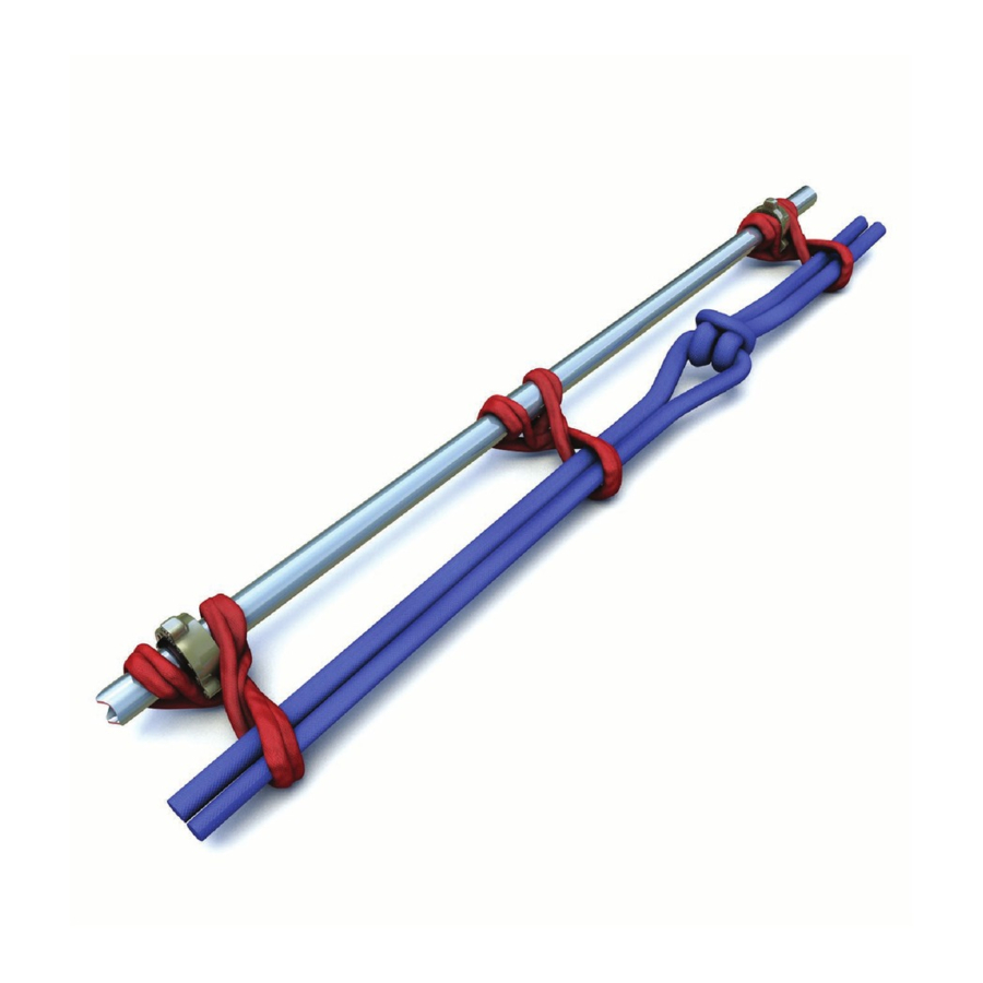
INSTALLING SPM FSR COMPONENTS ® - "RIB" INSTALLATION STEP 1 Begin by positioning the Rib beneath flow line as shown. The Rib profile should straddle the union assembly. NOTE THAT PIPING MIGHT REQUIRE ELEVATION IN ORDER TO FIT THE RIB BENEATH - SEE PAGE 22 “RECOMMENDED ASSEMBLY AID”... - Page 15 STEP 3 Continue to bring end “A” back around to form a second loop. Rib profile should still evenly straddle union assembly as shown. END “A” END “B” STEP 4 Draw end “A” even with “B” end as shown. Ensure that the Rib profile fits snugly around union assembly (or other applicable connection).
- Page 16 b) SPM FSR Ribs can NEVER be substituted for SPM ® ® Spines. c) No SPM FSR Ribs are required, or should be used, on anchor ® lines (Anchor lines are the separate SPM FSR lines that secure ® the entire SPM FSR system to separate anchor points).
- Page 17 RECOMMENDED ASSEMBLY AID It is typically necessary to raise the flow line piping in order to insert Ribs between union connections and the ground. Never attempt to lift piping manually. The suggested method is to use a “pipe jack” . A secondary method is to use a lever and fulcrum. Place lever under flow line as shown and temporarily lift piping to a minimal height using the following guidelines for reference: a) Do not lift piping more than 6-8 inches.
-
Page 18: Correct Rib Configuration
INSTALLING SPM FSR COMPONENTS ® - CORRECT RIB CONFIGURATION (Shown with SPM FSR Spine installed) ® PRIMARY Method This is the recommended method of installing SPM FSR Ribs. ® ROTATE “A” and “B” ends 270° from flat before installing SPM ®... - Page 19 SECONDARY Method Use this method only when there is not enough slack in the RIB material to allow for an additional twist. ROTATE “A” and “B” ends only 90° - 180° from flat before installing SPM FSR Spine. ® FSR Ribs should be installed as tight as possible. ®...
-
Page 20: Installing Fsr Components
INSTALLING SPM FSR COMPONENTS ® - REQUIRED RIB LOCATIONS UNION CONNECTIONS FSR Ribs should be installed on EVERY union connection ® on the flow line (one Rib per union). The Rib envelope must always straddle both sides of the union in order to help contain each end of the adjoining pipes/components. - Page 21 FSR Rib installed on each union ® connection at each end. However, on piping assemblies 10 feet or longer, Weir Oil & Gas requires that a third SPM FSR Rib ® also be installed midway between the two union connections as shown.
- Page 22 NOTES: a) There must be one SPM FSR Rib installed at each union ® connection. The Rib envelope should always straddle both sides of the union. This is critical in order to help restrain each end of the flow line components. b) It is recommended that all Ribs are installed on the flow line prior to installing the Spine-main line.
-
Page 23: Spine Linking
INSTALLING SPM FSR COMPONENTS ® – SPINE LINKING USE THIS PROCEDURE TO LINK SPINE RESTRAINTS TOGETHER TO CREATE ONE MAIN LINE (OR ANCHOR LINES) STEP 1 Lay out SPM FSR Spines end to end as shown. For illustration ® purposes only, we will consider ends “A” thru “D” for this procedure. - Page 24 STEP 3 Continue to pull “C” end thru “B” end. Insert “C” end back thru the “C-D” SPM FSR Spine as shown. As “C” is pulled further, ® unrestrained “D” end will move towards “B” end. STEP 4 Pull the remainder of “C” end thru until “D” end draws close to “B”...
- Page 25 STEP 5 With “C” end pulled taut, notice how “D” and “C” ends have switched places. Keeping “A/B” SPM FSR stationary, keep pulling ® “C” end until the “B/D” connection can no longer be tightened. FSR link should look like detail shown. ®...
-
Page 26: Anchor Crossover Assembly
ANCHOR CROSSOVER ASSEMBLY Anchor Clamp Half “D”-Type (1 of 2 required) Shackle (1 of 2 Required) Wing nut retainer segments & retainer ring Seal Ring Anchor Clamp “D”-Type Half Shackle (1 of 2 required) (1 of 2 Required) “D”-Type Shackle “C”-Type Shackle For Anchor Crossovers •... -
Page 27: Installing Fsr Components
INSTALLING SPM FSR COMPONENTS ® – ANCHOR CROSSOVER ASSEMBLY (PRIMARY METHOD) Generally, two Anchor Crossover assemblies are required for each swivel group assembly (two or more swivels in line), with one crossover assembly installed on each end. Anchor Crossovers are installed in this configuration because swivels and swivel assemblies are designed to provide flexibility in a flow line. -
Page 28: Crossover Assembly (Alternative Method)
INSTALLING SPM FSR COMPONENTS ® – NON-ANCHOR CROSSOVER ASSEMBLY (ALTERNATIVE METHOD) The following method provides an alternate method to install the FSR system without Anchor Crossovers at the ends of ® swivel groups (2 or more in series) and at anchor line end points by using additional linked spines in place of the Anchor Crossovers. - Page 29 1. Install SPM FSRs for swivel assemblies as described earlier ® in this Instruction Guide, except there are no Anchor Crossover Assemblies in this case. The set up is shown in Figure 2. a. The swivel assemblies should have SPM FSR Ribs ®...
- Page 30 Install two additional spines in place of anchor crossovers and loop around the “Anchor” type (or “C” type) shackle to straight section of the pipe connect the two additional Spines Figure 3. Additional Spines in Place of Anchor Crossover Assemblies Shown. For clarity purposes, the main line Spine and Ribs (shown in Figure 2) are not shown here.
- Page 31 B. Install SPM FSR Anchor Lines on the Main Flow Line to the ® Well Head 1. Figure 5 demonstrates the Main Flow Line and the set up of two FSR Anchor Lines. The directions towards the well head and ®...
- Page 32 Step 1 FSR Rib ® Step 2 Step 3...
- Page 33 END “B” FSR Spine 1 ® END “A” Figure 6. SPM FSR Connection Loops ® 3. Install the Left and Right SPM FSR Anchor Lines as shown in ® Figure 7 . Follow the looping procedure referenced in the following section.
-
Page 34: Securing Fsr System Ends
SECURING SPM FSR SYSTEM ENDS ® (This includes both SPM FSR main lines and SPM FSR anchor ® ® lines) THERE ARE TWO PRIMARY METHODS FOR SECURING THE FSR MAIN LINES AND SPM FSR ANCHOR LINES: ® ® LOOPING Looping the SPM FSR Spine around the anchor point, then ®... - Page 35 LOCATION SELECTED FOR TERMINATING THE FSR BE CAPABLE OF ENDURING A “ONE TIME” SHOCK LOAD OF 120,000 LB. REDUCED ANCHOR LOAD CAPABILITIES MAY BE ACCEPTABLE, DUE TO VARIATIONS IN PRESSURE RATING AND NOMINAL PIPE DIAMETER. CONTACT WEIR OIL AND GAS FOR ADDITIONAL RECOMMENDATIONS REGARDING ANCHOR LOCATIONS.
-
Page 36: Final Fsr System Inspection
FINAL SPM FSR SYSTEM ® INSPECTION (Always done before energizing the flow line) A) Make sure that the main SPM FSR line is continuous, meaning ® that all SPM FSR main lines and anchor line ends are secured ® to an appropriate anchor. This is important. If there is a break in the flow line, any discontinuity in the SPM FSR line could allow ®... -
Page 37: Linked Fsr Measurements
LINKED SPM FSR MEASUREMENTS ® USE THIS PROCEDURE TO DETERMINE APPROXIMATE AMOUNT OF OVERLAP WHEN LINKING SPM FSR COMPONENTS ® TOGETHER. 10 ft. 10 ft. 10 ft. Spines shown, 19 ft. though all spines would have similar reduction One foot overlap (two Spines) Note that linking the SPM FSR Spines together results in a slight... -
Page 38: Recommended Sequence When Installing Spm ® Fsr Components
Should you have anything other than a standard installation, it is strongly recommended you contact Weir Oil & Gas Engineering before proceeding. A standard installation sequence is as follows:... -
Page 39: Inspection
Flow Line Safety Restraint Annual Inspection Procedure. ® Proof Load Testing is also offered by Weir Oil & Gas. This testing requires multiple samples to be destroyed by pull-test. Though not mandatory, this testing offers an additional level of reassurance. -
Page 40: Limited Warranty And Limitations On Warranty
FSRs will be free from ® defects in workmanship and material for a period of six months. This is Weir Oil & Gas sole and limited warranty on this product. 2. Disclaimer ALL OTHER WARRANTIES, WHETHER EXPRESS OR IMPLIED, ARISING UNDER STATE OR FEDERAL LAW INCLUDING BUT... -
Page 41: Notes
NOTES... - Page 42 Document P/N: 2P37221M Release Date: 9/25/2014 Revision: 6 | Date: 2/4/2015...
Need help?
Do you have a question about the SPM Flow Line and is the answer not in the manual?
Questions and answers