Table of Contents
Advertisement
Quick Links
Multi-Channel Audio Interfaces Using AES67
AoIP - AVN Portals
AVN-PA8/T/D
AVN-PD8/T/D
AVN-PM8/T/D
8 Stereo Analogue Line Inputs & Outputs, AES67 Portal
8 Stereo Digital Line Inputs & Outputs, AES67 Portal
8 Mic/Line Inputs, 8 Stereo Line Outputs, AES67 Portal
Manufacturers of Audio Products for AV,
Installed Sound, Broadcast Radio & Broadcast TV
Advertisement
Table of Contents

Related Manuals for Sonifex AVN-PA8/T/D


Summary of Contents for Sonifex AVN-PA8/T/D
- Page 1 Multi-Channel Audio Interfaces Using AES67 AoIP - AVN Portals AVN-PA8/T/D 8 Stereo Analogue Line Inputs & Outputs, AES67 Portal AVN-PD8/T/D 8 Stereo Digital Line Inputs & Outputs, AES67 Portal AVN-PM8/T/D 8 Mic/Line Inputs, 8 Stereo Line Outputs, AES67 Portal Manufacturers of Audio Products for AV,...
- Page 2 Information in this document is subject to change without notice and does not represent a commitment on the part of the vendor. Sonifex Ltd shall not be liable for any loss or damage whatsoever arising from the use of information or any error contained in this manual.
-
Page 3: Table Of Contents
Navigation Control Reset Button Product Warranty - 2 Year Extended Power Button Sonifex Warranty & Liability Terms & Conditions 5. AVN-PA8/T/D 8 Stereo Analogue Line Inputs & Outputs, 1. Definitions AES67 Display Portal 2. Warranty Rear Panel Connections Unpacking Your Product AVN-PA8/AVN-PA8D 8 Stereo Analogue Line Inputs &... - Page 4 9. Front Panel System Menu Vgpio Sources Node Parameter Value Specification System Info 11. Technical Specifications Network AVN-PA8/T/D 8 Stereo Analogue Line Inputs & Outputs, Display AES67 Display Portal Meters AVN-PD8/T/D 8 Stereo Digital Line Inputs & Outputs, 10. Ember+ Interface...
- Page 5 Contents & Figures Fig 8-4: ‘GPIO Assignments’ Section of ‘GPIO Assignments’ Fig 8-30: ‘General’ Tab of ‘Configure Physical Output’ Window, Webpage (Terminal Version) AVN-PD8 Fig 8-5: ‘User Button GPIO Assignments’ Section of ‘GPIO Fig 8-31: ‘General’ Tab of ‘Configure Physical Output’ Window, Assignments’...
-
Page 6: Warranty
To register your product, please go online to www.sonifex.co.uk/register Sonifex Limited — 61 Station Road — Irthlingborough — Northamptonshire — NN9 5QE — United Kingdom Tel: +44 (0)1933 650 700 — Fax: +44 (0)1933 650 726 — Email: technical.support@sonifex.co.uk — Internet: www.sonifex.co.uk... - Page 7 This is the entire Contract between the parties relating to the subject matter hereof and may not be changed or terminated except in writing in As standard, Sonifex products are supplied with a 1 year back to base accordance with the provisions of this Contract. A reference to the consent, warranty.
- Page 8 Warranty vii. the Goods have been assembled or incorporated into other the results of that test. The report will be accurate at the time of the goods only in accordance with any instructions issued by the test, to the best of the belief and knowledge of the Company, and the Company;...
-
Page 9: Repairs & Returns
The available voltage settings are 115V, or 230V. Please note that all products are either switchable between 115V and 230V, Please contact Sonifex or your supplier if you have any problems with your or have a universal power supply. -
Page 10: Weee Directive
All products manufactured by Sonifex Ltd have the WEEE directive label Connect the equipment in accordance with the connection details and placed on the case. Sonifex Ltd will be happy to give you information about before applying power to the unit, check that the machine has the correct local organisations that can reprocess the product when it reaches its “end... -
Page 11: Multi-Channel Audio Mix Engines Using Aes67 Aoip, Avn Portals
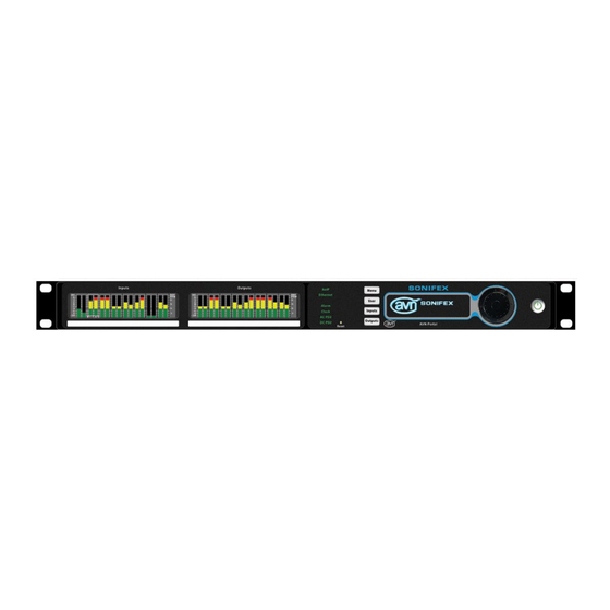
Fig 1-2: The AVN-Portal Front Panel with Meter Display adjusted at the input, output or crosspoint along with the addition of a The AVN portals are part of the Sonifex range of IP based AVN (Audio/ high-pass and low-pass filter on all inputs and outputs. -
Page 12: Avn-Pd8 8 Stereo Digital Line Inputs & Outputs, Aes67 Portal
AVN-Portals and output streams are advertised using Avahi/Bonjour and SAP. AVN-PD8 8 Stereo Digital Line Inputs & Outputs, AES67 Portal • 8 x stereo digital AES3 inputs and 8 x stereo digital AES3 outputs on The rear panel contains IEC mains and DC power inputs which allow for power D-type sockets with AES59 pinout, paralleled with 8 x RJ45 connectors redundancy. -
Page 13: Headphone Distribution System
AVN-Portals Headphone Distribution System The portals can be combined with the Sonifex AVN-HA1 and to listen to the outputs, with the portals providing power and audio AVN-HD1 headphone amplifiers to provide 8 separate headphone signals. The switches on the front panel of the AVN-HA1 and AVN-... -
Page 14: Quick Start Guide
System Info menu item on page 54 for details. This section outlines the steps required to get an AVN portal setup and 7. If a dedicated grandmaster clock, such as the AVN-GMC from Sonifex, is routing audio. going to be used as the master PTP clock for the network audio system, 1. -
Page 15: Installation
12V DC power supply, part number AVN-DC150. The AVN-PA8 has 8 analogue balanced stereo inputs. The AVN-PD8 has 8 Please contact Sonifex Ltd sales for more details. Both power supplies can digital AES3 inputs and the AVN-PM8 has 8 balanced mono mic/line inputs. -
Page 16: Front Panel Controls, Indicators & Displays
CE Conformity Front Panel Controls, Indicators & Displays 4. Front Panel Controls, Indicators & Displays Status User Menu OLED Navigation Indicators Button Button Display Control Reset Inputs Outputs Power Switch Button Button Button Fig 4-1: The AVN-Portal Front Panel Inputs Outputs Status User... -
Page 17: Clock
Front Panel Controls, Indicators & Displays CE Conformity Amber DC voltage is less than +11V or greater than +13V. This Clock Indicates the status of PTP clock as follows. indicates a warn condition. Green The unit is a PTP slave with a clock offset of less or equal to Not connected or DC voltage is less than +10V or greater ±1µs or the unit is the PTP master. -
Page 18: Meter Display
CE Conformity Front Panel Controls, Indicators & Displays shows the device ID, friendly name, the user button settings, and on and out of menus, the up and down buttons or rotary control to move up devices without a meter panel, confidence metering of the physical inputs and down menus and the centre button to move into menus. -
Page 19: Fig 5-1: Avn-Pa8/Avn-Pa8D Rear Panel
AVN-PA8/T/D 5. AVN-PA8/T/D 8 Stereo Analogue Line Inputs & Outputs, AES67 Display Portal Rear Panel Connections Pin 9: Channel 3 – (Non-phase) Pin 10: Channel 2 + (Phase) AVN-PA8/AVN-PA8D 8 Stereo Analogue Line Inputs & Outputs, Pin 11: Channel 2 ground... - Page 20 AVN-PA8/T/D RJ45 Stereo Line Input Connections Pin 12: Channel 1 – (Non-phase) The AVN-PA8 and AVN-PA8D have 8 female analogue RJ45 inputs. Analogue Pin 13: No connection RJ45s connections for inputs use the StudioHub+ pinout, these connections Pin 14: Channel 8 – (Non-phase) are paralleled with the D-Sub (DB-25) connections.
-
Page 21: Output Terminal Connections, Aes67 Portal
AVN-PA8/T/D relay contact. This has the following pinout. AVN-PA8T/AVN-PA8TD 24-Pin Phoenix Style Stereo Line Input/ Output Terminal Connections, AES67 Portal Pin 1: GPIO Port 1 24-Pin Phoenix Style Stereo Line Input Terminal Connections Pin 2: GPIO Port 2 The AVN-PA8T and AVN-PA8TD have 2 female 24-pin Phoenix style terminal... - Page 22 AVN-PA8/T/D Pin 13: Channel 3L ground Pin 20: Channel 8L + (Phase) Pin 14: Channel 3L + (Phase) Pin 21: Channel 8L – (Non-phase) Pin 15: Channel 3L – (Non-phase) Pin 22: Channel 8R ground Pin 16: Channel 3R ground...
- Page 23 AVN-PA8/T/D Pin 19: Channel 4L ground The AVN-PA8T and AVN-PA8TD have a single female Phoenix style terminal Pin 20: Channel 4L + (Phase) block, this provides 10 configurable GPIO and a voltage free switching relay Pin 21: Channel 4L – (Non-phase) contact.
-
Page 24: Network Interfacing Rj45 Connections
AVN-PA8/T/D GPIO ports can be set up as GPO or GPI. GPO are open collector, this means SFP Interface the output pin is connected to ground when the GPO is active. GPI are AoIP active low this means they are triggered when pulled down to ground. GPIO All units in the portal series are fitted with an SFP (Small Form-factor configuration can be managed through the devices embedded web server. -
Page 25: Avn-Pd8/T/D 8 Stereo Digital Line Inputs & Outputs, Aes67 Portal
AVN-PD8/T/D 6. AVN-PD8/T/D 8 Stereo Digital Line Inputs & Outputs, AES67 Portal Rear Panel Connections Pin 14: Out Channel 7/8 – (Non-phase) Pin 15: Out Channel 5/6 + (Phase) AVN-PD8/AVN-PD8D Pin 16: Out Channel 5/6 ground D-Sub (DB-25) Stereo Digital Inputs And Outputs Pin 17: Out Channel 3/4 –... -
Page 26: Output Terminal Connections, Aes67 Portal
AVN-PD8/T/D Pin 5: Cough/Mute (Active low) The +12V supply is fused and has a maximum output current of 200mA. Pin 6: No connection GPIO ports can be set up as GPO or GPI. GPO are open collector, this means Pin 7: No connection the output pin is connected to ground when the GPO is active. - Page 27 AVN-PD8/T/D Pin 14: Channel 9/10 + (Phase) Pin 18: Channel 11/12 – (Non-phase) Pin 15: Channel 9/10 – (Non-phase) Pin 19: Channel 13/14 ground Pin 16: Channel 11/12 ground Pin 20: Channel 13/14 + (Phase) Pin 17: Channel 11/12 + (Phase) Pin 21: Channel 13/14 –...
-
Page 28: Network Interfacing Rj45 Connections
AVN-PD8/T/D Pin 20: Ground SFP Interface Pin 21: Relay – Normally Closed Contact AoIP Pin 22: +12VDC All units in the portal series are fitted with an SFP (Small Form-factor Pin 23: Relay – Common Pluggable) port this allows the user to install a SFP transceiver of their Pin 24: Relay –... -
Page 29: Avn-Pm8/T/D 8 Mic/Line Inputs, 8 Line Outputs, Terminal Block, Aes67 Portal
AVN-PM8/T/D 7. AVN-PM8/T/D 8 Mic/Line Inputs, 8 Line Outputs, Terminal Block, AES67 Portal Rear Panel Connections Pin 1: I/O Left + (Phase) Pin 2: I/O Left – (Non-phase) AVN-PM8/AVN-PM8D Pin 3: I/O Right + (Phase) XLR Mic/Line Inputs Pin 4: Ground The AVN-PM8 and AVN-PM8D have 8 female XLR connections used as Pin 5:... -
Page 30: Output Terminal Connections, Aes67 Portal
AVN-PM8/T/D Pin 9: GPIO Port 6 Pin 5: Channel 2 + (Phase) Pin 10: GPIO Port 7 Pin 6: Channel 2 - (Non-phase) Pin 11: GPIO Port 8 Pin 7: Channel 3 ground Pin 12: GPIO Port 9 Pin 8: Channel 3 + (Phase) Pin 13: GPIO Port 10... - Page 31 AVN-PM8/T/D L – Left Pin 4: Channel 5R ground R – Right Pin 5: Channel 5R + (Phase) Pin 6: Channel 5R - (Non-phase) Pin 7: Channel 6L ground Block 1 Pin 1: Channel 1L ground Pin 8: Channel 6L + (Phase) Pin 9: Channel 6L –...
-
Page 32: Network Interfacing Rj45 Connections
AVN-PM8/T/D Pin 8: Ground Ethernet Pin 9: +12VDC All devices in the AVN portal series have a female RJ45 used for network Pin 10: GPIO Port 5 interfacing, this is the top port and is used to access the devices embedded Pin 11: GPIO Port 6 web server. -
Page 33: Embedded Web Server
The active IP address for the network port can be found using a service discovery tool such as the ‘Discovery Application’ which can be found on the Sonifex website (http://sonifex.co.uk/technical/software/index.shtml#sfxsrvdisc) or Bonjour Print Services. Alternatively, the user can display the IP address on the main display of the device by navigating to the ‘Device Information’... -
Page 34: Information
This information shows the current status of the unit as well as the software versions of the various modules running on the unit. When contacting Sonifex technical support, it is important to provide the information shown on this page. Fig 8-1: Upper Section of Device Information Web Page... -
Page 35: Gpio Assignments
Embedded Web Server The lower half of the page shows the status of the Precision Time Protocol (PTP) clock, as well as the configuration of the network ports as shown: The network IP addresses and subnet masks shown are the actual values currently in use. -
Page 36: Fig 8-3: 'Gpio Assignments' Section Of 'Gpio Assignments Webpage (Rj45 Version)
Embedded Web Server GPIO Assignments Fig 8-4: ‘GPIO Assignments’ Section of ‘GPIO Assignments’ Webpage (Terminal Version) This section displays information about the physical GPIO port assignments. Each port can be an input or an output or it can be disabled. Inputs can activate local functions and trigger virtual GPO. -
Page 37: Fig 8-5: 'User Button Gpio Assignments' Section Of 'Gpio
Embedded Web Server User Button GPIO Assignments Virtual GPIO Assignments Fig 8-5: ‘User Button GPIO Assignments’ Section of ‘GPIO Assignments’ Webpage This section displays information about the user buttons on the front panel of the devices and their corresponding LEDs. Fig 8-6: ‘Virtual GPIO Assignments’... -
Page 38: Configuration
Embedded Web Server Configuration Address Mode – Each network port has its own independent address mode which determines how the port obtains its IP address. When set to There are five sections under the ‘Configuration’ tab, these are as follows. dynamic, the unit will attempt to acquire an IP address automatically from •... -
Page 39: Ptp Profiles Web Page
Embedded Web Server Network Defaults Active Profile – There are 3 PTP profiles available: Default, AES67 Media Friendly Name: AVN-PA8-xxxxxxx and Custom. This dropdown list selects which of the profiles will be active. Where xxxxxxx is the product serial number DSCP –... -
Page 40: Fig 8-8: Upper Section Of Ptp Profiles Web Page
Embedded Web Server Announce Interval – This is the rate at which the announce message is sent, one per the selected time. The announce message forms part of the Best Master Clock Algorithm (BMCA) and contains the properties of the clock which sends it. - Page 41 Embedded Web Server Slave Only – This option limits the unit to being a slave PTP clock only. Custom Profile: Delay Mechanism: Sync System Clock – When this option is selected, the system clock (i.e. the Announce Interval: 2 secs date and time) of the unit is synchronised with the PTP master.
-
Page 42: Display Settings
Embedded Web Server Display Settings On all devices the ‘Front Panel Settings’ section should be available, on devices with a meter panel the ‘Meter Panel Settings’ section should also be available. The following devices have a metering panel. AVN-PA8D AVN-PA8TD AVN-PD8D AVN-PD8TD AVN-PM8D... -
Page 43: Fig 8-10: 'Front Panel Settings' Section Of 'Display Settings
Embedded Web Server Front Panel Settings User Button ‘N’ Function This allows the user to perform a function when button ‘n’ on the front panel is pressed, where ‘n’ is 1, 2 or 3, the options available are ‘None’, ‘GPIO’, ‘Input Menu Shortcut’ and ‘Output Menu Shortcut’. ‘None’... -
Page 44: Fig 8-11: 'Meter Panel Settings' Section Of 'Display Settings
Embedded Web Server Meter Panel Settings Meter Mode This section is only available on devices with a ‘Meter Display’ (device ID This can be set to either ‘Discrete’ or ‘Continuous’ and changes the ends in a ‘D’) appearance of the meter bar of the meter display. Fig 8-12: Discrete Meter Mode Image Fig 8-13: Continuous Meter Mode Image Fig 8-11: ‘Meter Panel Settings’... - Page 45 Embedded Web Server Normal Layout Scale Range Without Scale Range with Phase 0dBFS Start of Amber Start of Meter Characteristics Phase Meter Meter Reference Section Red Section Dual PPM + Standard VU -8 to +12dBu -2 to +12dBu +18dBu 0dBu +8dBu EBU PPM -9 to +12 dBu...
-
Page 46: Audio Routing
Embedded Web Server Channel Idents The identities of channels can be displayed either above the metering when ‘Show -Top’ is selected, below the metering when ‘Show – Bottom’ is selected or hidden by selecting ‘Hidden’. Phase Metering This shows the phase difference of the signal on the left and right channel of an input or output. -
Page 47: Fig 8-15: 'Aoip' Tab Of 'Add New Aoip Input Stream' Window
Embedded Web Server In the ‘AoIP’ tab, the ”Stream Name” drop-down box contains a list of all the streams that have been discovered on the network when a stream is selected in this drop-down, information about the stream is shown. The information shown includes: •... -
Page 48: Fig 8-16: 'Aoip' Tab Of 'Add New Aoip Input Stream' Window, With Manual Entry Checkbox Selected
Embedded Web Server As with the discovered streams, a “Buffer delay” can be set before clicking the Add button to add the stream to the grid. Fig 8-17: ‘General’ Tab of the ‘Add New AoIP Input Stream’ Window In the ‘General’ tab the value in the ‘Stream Name’ field of the stream you have selected in the ‘AoIP’... -
Page 49: Fig 8-18: 'Eq' Tab Of The 'Add New Aoip Input Stream' Window
Embedded Web Server been added to the grid, click on the name of the AoIP input stream in the “INPUTS” list to bring up the same menu described above. In this menu, it is also possilbe to remove the AoIP input stream from the grid list by clicking the “Remove”... -
Page 50: Fig 8-20: 'Aoip' Tab Of The 'Add New Aoip Out Stream' Window
Embedded Web Server By default, the ‘Name’ field has the friendly name of the unit followed by In the ‘AoIP’ tab the stream name can again be seen in the ‘Stream Name’ a hyphen and the stream number, this can be changed by modifying the field. -
Page 51: Fig 8-21: 'Eq' Tab Of The 'Add New Aoip Out Stream' Window
Embedded Web Server Collapse When the ‘Collapse’ button is pressed the routing grid is minimised. Each channel is hidden and instead, an overview of the routings is shown. If any channels from an input stream are routed to any channels of an output stream, the corresponding grid box will be coloured in light green. -
Page 52: Fig 8-22: 'Eq' Tab Of The 'Configure Physical Input' Window
Embedded Web Server • Name • The ‘High Pass Filter’ can be enabled by selecting the ‘On’ checkbox. This • Trim (dB) removes low frequency components from a signal. The frequency of the • Mute lowest components to be allowed can be set using the ‘+’ and ‘-’ buttons The ‘Name’... -
Page 53: Fig 8-24: 'General' Tab Of The 'Configure Physical Input' Window On The Avn-Pm8 (Signal Level: Mic)
Embedded Web Server AVN-PA8 devices also have an audio line up configuration option using the ‘Audio Line Up’ dropdown menu. The line-up level can be set to determine the analogue audio level that is equal the 0dBFS full scale digital value. This can be set to either 15, 18, 20, 22, or 24 dBu. -
Page 54: Fig 8-26: 'General' Tab Of The 'Configure Physical Input' Window On The Avn-Pd8
Embedded Web Server The ‘Signal Level’ can be set to either ‘Mic’ or ‘Line’. Selecting ‘Mic’ displays AVN-PD8, AVN-PD8D, AVN-PD8T and AVN-PD8TD the options for ‘Phantom Power’ and ‘Preamp Gain’ whereas selecting ‘Line’ displays the ‘Audio Line Up’ option. When an input is set to mic level a icon will be shown next to the input name. -
Page 55: Fig 8-27: 'Aoip' Tab Of 'Edit Aoip Input Stream' Window
Embedded Web Server AoIP Inputs the same as the window that opens up when ‘Add AoIP In Stream’ is pressed, however there are a couple of extra features under the ‘AoIP’ tab. If the stream was added manually, by clicking ‘Manual Entry’, at the top of the ‘AoIP’... -
Page 56: Fig 8-28: 'Eq' Tab Of 'Configure Physical Output' Window
Embedded Web Server the signal being output can be adjusted using the value in the ‘Trim’ field. • The ‘Low Pass Filter’ can be enabled by selecting the ‘On’ checkbox. This The value in this field can be modified by pressing the ‘+’ and ‘-’ buttons or removes high frequency components from a signal. -
Page 57: Fig 8-30: 'General' Tab Of 'Configure Physical Output' Window, Avn-Pd8
Embedded Web Server AVN-PA8 devices also have an audio line up configuration option using the AVN-PM8, AVN-PM8D, AVN-PM8T and AVN-PM8TD ‘Audio Line Up’ dropdown menu. The line-up level can be set to determine the analogue audio level that is equal the 0dBFS full scale digital value. This can be set to either 15, 18, 20, 22, or 24 dBu. -
Page 58: Fig 8-32: 'Configure Aoip Output' Window Of 'Audio Routing' Webpage
Embedded Web Server AoIP Outputs Clicking the name of an AoIP output stream, located along the top of the routing grid, opens a window entitled ‘Configure AoIP Output’, this window is essentially the same as the window that opens up when ‘Add AoIP Out Stream’... -
Page 59: Fig 8-33: Image Of 'Routing Grid' Of 'Audio Routing' Webpage
Embedded Web Server Routing Fig 8-33: Image of ‘Routing Grid’ of ‘Audio Routing’ Webpage... -
Page 60: Gpio Settings
Embedded Web Server Clicking on a box in line with an input/output when that input/output is GPIO Settings minimised will maximise that input/output, this then allows the routing of individual channels between that input/output. Routing is achieved by clicking on a box which is in line with an input/output channel, this will cause the audio from the input channel to be routed to the selected output channel. -
Page 61: Fig 8-35: 'Output Relay Settings' Section Of 'Gpio Settings' Webpage
Embedded Web Server Input • Cough n (where n is from 1 to 8) – Active when Cough n is activated. • When set to an ‘Input’ an ‘Input Function’ option is available. This allows • vGPI n (where n is from 1 to 10) – Active when vGPI n is activated. a specific function to be assigned to an output, for example, an input can •... -
Page 62: System Tab
• New versions of firmware will be released as new features are added, and when any bug fixes are completed. Click on the software downloads link to visit the Sonifex web page. If an update is available, download the latest file. The file will have the ‘SWU’... -
Page 63: Fig 8-38: Save Configuration Section Of Update Webpage
Embedded Web Server Save Configuration to A File file are ignored. If you also wish to use the network settings from the uploaded json file, ensure that the “Overwrite Network Settings” check box is ticked. • Click the browse button and locate the required configuration file and then click the LOAD CONFIG button. -
Page 64: Front Panel System Menu
Front Panel System Menu 9. Front Panel System Menu All AVN portal series devices have the following options available in their ‘Main Menu’; The system menu, accessed via the front panel, offers alternative access to a limited set of options and information. Each layer of the menu structure, → System Info apart from the main menu, has a ‘BACK’... -
Page 65: Network
Front Panel System Menu → IP Address → Static Settings → Subnet Mask → IP Address → MAC Address → Subnet Mask → PTP Clock → Back → Status → Close → Domain Number → Back → Master Offset → Close → Profile → Auto Multicast → AC-DC Voltage → Back → DC Voltage → Close → Version... -
Page 66: Meters
Front Panel System Menu Meters The ‘Meters’ sub-menu allows the type of scale used on the meter display to be selected, it also allows adjustment of the meter displays brightness and allows any of the input or output channels to be selected and displayed full size on the input or output display. -
Page 67: Ember+ Interface
Ember+ Interface 10. Ember+ Interface the Ember+ provider tree. In Ember+ viewer, nodes are identified by a blue dot and parameters are indicated by a green leaf icon. Parameters Each device in the AVN portal series has an Ember+ provider interface whose names are shown in blue text can be modified by the user, all other that exposes various configuration options. -
Page 68: Network Node
Ember+ Interface Network Node The network node contains information on the network configuration of the unit. Fig 10-4: Options available after selection Eth0 Mode Allows the user to select between ‘Static’ and ‘Dynamic’ addressing modes. IP Address Allows the user to enter an IP address for the device which is used when Fig 10-3: Ember+ Network Branch Structure the device is in the ‘Static’... -
Page 69: Eth1
Ember+ Interface Audio Routing Node MAC Address This specifies the MAC address of the port. Eth1 Mode Allows the user to select between ‘Static’ and ‘Dynamic’ addressing modes. IP Address Allows the user to enter an IP address for the device which is used when the device is in the ‘Static’... -
Page 70: Parameters Node
Ember+ Interface Each of these options can be selected and adjusted. Parameters Node Targets Connections A list of all the devices outputs, each of the outputs can have their specific This shows connections between input and output channels, for example settings changed. -
Page 71: Matrix
Ember+ Interface Matrix Selecting matrix from the list bring up the following display; Fig 10-9: Matrix used for routing audio... -
Page 72: Gpio Node
Ember+ Interface This shows all of the devices input channels down the left-hand side and all Output Trigger Parameter This string parameter is the function that triggers the GPIO port when it is the devices output channels along the top of the matrix, by clicking on a box where an input channel and an output channel intersect, the audio from the configured as an output. -
Page 73: Output Triggers Parameter
Ember+ Interface Output Triggers Parameter Type Parameter String parameter with comma separated list of assigned triggers. The names This enumerated integer parameter is the current port type. This parameter of the triggers that can be added to the list are available under the Triggers indicates whether the virtual GPIO is disabled, or set to be an input or an Node, see page 64. -
Page 74: Handlers Node
Ember+ Interface Parameter Value Specification Handlers Node The parameters under the handlers node contain the names of all the This section provides a full list of the possible parameter values for the handlers that can be assigned to GPIO inputs. The names can be used with Ember+ interface. - Page 75 Ember+ Interface → False (Off) → 4 (+24 dBu) → True (On) → HPF Enable (Boolean) → Line-up (Integer) → False (Off) → 0 (+15 dBu) → True (On) → 1 (+18 dBu) → HPF Frequency (Integer) → 2 (+20 dBu) → 40 (Min) → 3 (+22 dBu) → 10000 (Max) → 4 (+24 dBu) → LPF Enable (Boolean) → HPF Enable (Boolean) → False (Off) → False (Off) → True (On) → True (On) → LPF Frequency (Integer)
- Page 76 Ember+ Interface → 2 (Output) → Active Triggers (String) → Input Function (String) → Trigger leaf values of active triggers (Example: Eth Link → Handler leaf value found in handler section Down) for multiple triggers follow this value with a (Example: Mute phys out 1: PHYS OUT 1) comma and another trigger leaf value from the trigger → Output Trigger (String) section (Example: Eth Link Down, AoIP Link Down) → Trigger leaf value found in trigger section → Status (Read only, Boolean)
- Page 77 Ember+ Interface → Input Function (String) → Handler leaf value found in handler section (Example: Mute phys out 1: PHYS OUT 1) → Input Mode (Integer) → 0 (Latching) → 1 (Momentary) → Status (Boolean) → False (Inactive input/output) → True (Active input/output) → LED * → Type (Integer) → 0 (Disabled) → 2 (Output) → Output Trigger (String) → Trigger leaf value found in trigger section (Example: Eth Link Down) → Status (Boolean) → False (Inactive input/output) → True (Active input/output)
-
Page 78: 11. Technical Specifications
Technical Specifications 11. Technical Specifications AVN-PA8/T/D 8 Stereo Analogue Line THD+N: < -110dBFS, -30dBFS, 20Hz to 20kHz, 20kHz BW Inputs & Outputs, AES67 Display Portal Noise: -110dBFS, 20kHz BW, Rs=200Ω Crosstalk: < -100dB Audio-Over-IP Specification Common Mode Rejection: > 70dB @ 1kHz Open Standards:... -
Page 79: Avn-Pd8/T/D 8 Stereo Digital Line Inputs & Outputs, Aes67 Portal
Technical Specifications Outputs: 2 24-Pin Phoenix style terminal blocks. Accessories (Analogue pinout) AVN-DC150: 150W DC power supply with KPJX-4S plug. GPIO: 1 24-Pin Phoenix style terminal blocks. AVN-HA1: Analogue Headphone Amplifier. Network: 2 x Gigabit Ethernet, RJ45’s. AVN-PD8/T/D 8 Stereo Digital Line Inputs & 1 x SFP fibre. - Page 80 Technical Specifications 0dBFS Line-Up: Adjustable +15/+18/+20/+22/+24dBu Dimensions (Boxed): 59cm (W) x 28cm (D) x 11cm (H) 23” (W) x 11” (D) x 4.3” (H) Frequency Response: 20Hz to 20kHz, +0/-0.2dB Weight: Nett: 3.0kg Gross: 3.7kg THD+N: < -110dBFS, -30dBFS, 20Hz to 20kHz, 20kHz BW Nett: 6.6lbs Gross: 8.1lbs Noise: -110dBFS, 20kHz BW, Rs=200Ω...
-
Page 81: Avn-Pm8/T/D 8 Mic/Line Inputs, 8 Line Outputs, Terminal
Technical Specifications AVN-PD8TD: Advanced audio routing, metering and Ember+ Interface Connection equalisation unit with terminal type digital Interface Type: Provider inputs, terminal type analogue outputs, Network Interface: Ethernet port and AoIP port RAVENNA AoIP, and a detailed customisable Port: 9000 display. - Page 82 Technical Specifications Connections AVN-PM8TD: Advanced audio routing, metering and equalisation unit with terminal type analogue AVN-PM8/D mic/line inputs, terminal type analogue outputs, Inputs: XLR connectors with phantom power (toggle). RAVENNA AoIP, and a detailed customisable Outputs: RJ45 connections (StudioHub+ pinout). display.
-
Page 83: Additional Information
Additional Information 12. Additional Information DSCP Name DS Field Value IP Precedence (Description) 0: Best Effort CS1, AF11-AF13 8, 10, 12, 14 1: Priority CS2, AF21-AF23 16, 18, 20, 22 2: Immediate CS3, AF31-AF33 24, 26, 28, 30 3: Flash (mainly used for voice signalling) CS4, AF41-AF43 32, 34, 36, 38 4: Flash Override... - Page 84 . s o n i f e x . c o . u k t:+44 (0)1933 650 700 f:+44 (0)1933 650 726 sales@sonifex.co.uk...
Need help?
Do you have a question about the AVN-PA8/T/D and is the answer not in the manual?
Questions and answers