
Related Manuals for TELEVAC MM200


Summary of Contents for TELEVAC MM200
- Page 1 MM200 TELEVAC THE FREDERICKS COMPANY A DIVISION OF 2400 PHILMONT AVE. HUNTINGDONVALLEY, PA 19006...
-
Page 2: Table Of Contents
TELEVAC INSTRUMENT MANUAL VACUUM GAUGE MODEL MM200 PARTS ITEM DESCRIPTION MM200 Instruction Manual AC Power Cable Power supply module 1 SET Rubber Feet 160Phone:(215) 947-2500 fax:(215) 947-7464 e-mail:sales@televac.com web site:www.televac.com MM-200_im REV M Page 1 of 160... -
Page 3: Table Of Contents
TELEVAC INSTRUMENT MANUAL VACUUM GAUGE MODEL MM200 TABLE OF CONTENTS SECTION TITLE PAGE TABLE OF CONTENTS INTRODUCTION DESCRIPTION STANDARD FEATURES Measurement Expansion Sensor interface Modules Computer Interface Modules Non-volatile Memory Display Keyboard CPU Configuration SETPOINT RELAYS VACUUM GAUGE TUBES Diaphragm... - Page 4 TELEVAC INSTRUMENT MANUAL VACUUM GAUGE MODEL MM200 SECTION TITLE PAGE INSTALLATION MODULE CONFIGURATION LINE VOLTAGE SELECTION GAUGE CONTROLLER INSTALLATION Freestanding Rack Mounted GAUGE SENSOR INSTALLATION WARNINGS VACUUM CONNECTION FITTINGS NPT Pipe Thread Connections 0-ring Compression Fittings Conflat Flange Fittings KF Flange Connections...
- Page 5 TELEVAC INSTRUMENT MANUAL VACUUM GAUGE MODEL MM200 SECTION TITLE PAGE OPERATION DISPLAY DESCRIPTION DEFINITIONS Station Number Data Display Units Gas Type Leak Rate Indicator Setpoint Relay Status Indicator ERROR INDICATIONS KEYPAD DESCRIPTION PUSHBUTTON Functions TEST/OP Pushbutton SETUP Pushbutton N2/GAS Pushbutton...
- Page 6 TELEVAC INSTRUMENT MANUAL VACUUM GAUGE MODEL MM200 SECTION TITLE PAGE SETUP INTIALIZATION Initial Displays USE OF PUSHBUTTONS TEST/OP Pushbutton Return to Normal Operation Self-Diagnostic Test UP/DOWN Arrows SETUP Pushbutton Cold Cathode Setup 3D & 3E Hot Cathode Setup Degass Timer Relay Setpoints SP#1 –...
- Page 7 PREF #xx RS485 Prefix and Addresses Table – For Software Ver. 2.31 or Higher New Commands For MM200 - For Software Ver. 2.31 or Higher Commands That Have Been Updated For 3F Modules Commands For The 3F Hot Cathode MINI-BA Module COMMUNICATIONS –...
- Page 8 TELEVAC INSTRUMENT MANUAL VACUUM GAUGE MODEL MM200 SECTION TITLE PAGE COMMAND SUMMARY – FOR SOFTWARE VER. 1.19 – 1.20 Communications 127 Data Output Hot Cathode Leak Rate Output Formats Set Points Set Point Setting Values COMMUNICATIONS – FOR SOFTWARE VER. 1.0 – 1.19...
- Page 9 TELEVAC INSTRUMENT MANUAL VACUUM GAUGE MODEL MM200 SECTION TITLE PAGE CALIBRATION ELECTRICAL "VERIFICATION" Equipment Required Procedure VACUUM CALIBRATION Equipment Required Procedure CALIBRATION FOR ALTERNATE GASSES SPECIFICATIONS 134. CONTROLLER SPECIFICATIONS CONTROLLER DIMENSIONS SENSORS ORDERING INFORMATION TROUBLESHOOTING PRELIMINARY TROUBLESHOOTING SETUP OF MODULE BOARDS...
- Page 10 TELEVAC INSTRUMENT MANUAL VACUUM GAUGE MODEL MM200 SECTION TITLE PAGE 1000 MISCELLANEOUS CALIBRATION MODE DIAPHRAGM GAUGES INSTALLATION OF EPROMS 160Phone:(215) 947-2500 fax:(215) 947-7464 e-mail:sales@televac.com web site:www.televac.com MM-200_im REV M Page 9 of 160...
-
Page 11: Introduction
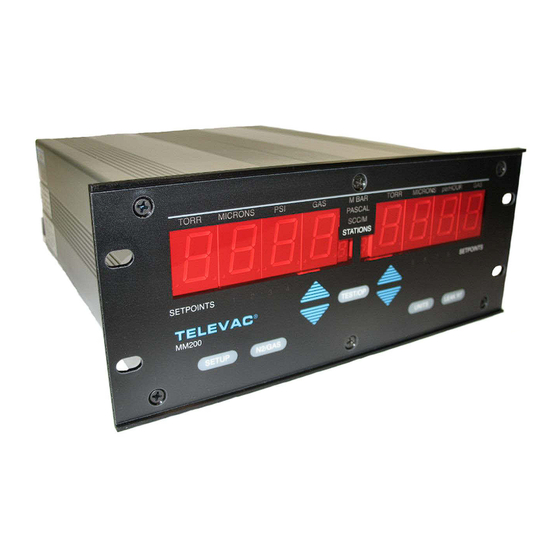
VACUUM GAUGE MODEL MM200 INTRODUCTION This manual provides information pertaining to the installation, operation, and maintenance of the Televac MM 200 vacuum gauge. Various sensor modules, their options, and associated sensors are covered in this manual. Fig. 1.1 - TELEVAC Modular Gauge... -
Page 12: Standard Features
TELEVAC INSTRUMENT MANUAL VACUUM GAUGE MODEL MM200 STANDARD FEATURES MEASUREMENT EXPANSION - The electronics unit can support additional measurement modules. These additional modules can be any mix of the above listed sensors. SENSOR INTERFACE MODULES - Each gauge has several available sensor interface modules (See Section 300). -
Page 13: Diaphragm
The 7FCS quick start gauge has a thermo emission igniter inside so every time when power applies to MM200 the filament goes on for 5 second to start ionization chain reaction.There are various designs to cover different pressure (vacuum) ranges. -
Page 14: Capacitance Diaphragm Gauge
TELEVAC INSTRUMENT MANUAL VACUUM GAUGE MODEL MM200 VACUUM GAUGE TUBES (cont.) CAPACITANCE DIAPHRAGM GAUGE - Measures absolute pressure by detecting very small deflections of a metal diaphragm via a change in capacitance between the diaphragm and one or more electrodes. It is not sensitive to gas type. -
Page 15: Initial Checkout
You may wish retain the packing material for later use. If the instrument must be returned to TELEVAC be sure to contact the service department (215-947-2500) for a Return Material Authorization (RMA) number. Items will not be accepted without an assigned RMA. -
Page 16: Initial Displays
TELEVAC INSTRUMENT MANUAL VACUUM GAUGE MODEL MM200 POSITION #0 CC 7E RS485 WARNING: Voltages may exist on rear panel connectors. DO NOT touch the exposed connectors when power is connected to the instrument. Note that the rear panel configuration shown in Fig. 2.1 is just one of the many possible combinations of gauges and relay modules. - Page 17 TELEVAC INSTRUMENT MANUAL VACUUM GAUGE MODEL MM200 Fig. 2.2 – Front Panel Fig. 2.3 – Software Version 160Phone:(215) 947-2500 fax:(215) 947-7464 e-mail:sales@televac.com web site:www.televac.com MM-200_im REV M Page 16 of 160...
- Page 18 Fig. 2.4 - Typical Initial Display If further checkout is desired, refer to Section 502. Assuming that the initial display check is successful, the instrument if ready for installation. Otherwise contact your TELEVAC Service Department (See front cover). 160Phone:(215) 947-2500 fax:(215) 947-7464 e-mail:sales@televac.com web site:www.televac.com...
-
Page 19: 300 Installation
The MM200 has six slots, which can be populated with various Televac modules. There is also a half slot that can be used to insert a communications module. This is the only slot into which the communications module can be inserted. - Page 20 WARNING: All relays must be assigned to a station when first installed, even if they will not be used (any station will suffice). Allowable configurations for the MM200 are shown in Table 3.1. 160Phone:(215) 947-2500 fax:(215) 947-7464 e-mail:sales@televac.com web site:www.televac.com...
- Page 21 TELEVAC INSTRUMENT MANUAL VACUUM GAUGE MODEL MM200 Table 3.1a - Examples of Allowable Configurations for the MM200 STATIONS RELAYS STATIONS RELAYS STATIONS RELAYS STATIONS RELAYS STATIONS RELAYS EPLANATION OF TERMS USED 2X = Dual station Thermocouple, Convection, Diaphragm, 7F Cold Cathode or single slot 7E cold...
- Page 22 2 additional sensors but only 1 2 additional sensors in a daisy cold cathode chain hook up of up to 4000’ REMOTE HOT CATHODE MODULE(S) VIA` MM200 One of several possible combinations using the remote hot cathode module 160Phone:(215) 947-2500 fax:(215) 947-7464 e-mail:sales@televac.com web site:www.televac.com...
- Page 23 TELEVAC INSTRUMENT MANUAL VACUUM GAUGE MODEL MM200 (CONTINUED) Table 3.1c – Allowable Configuration for the MM200 (Continued) RS232 Link Computer * Optional thermocouple, diaphragm, convection or cold cathode gauges. Maximum # remote station = 3 Including the hot cathode. REMOTE HOT CATHODE MODULE(S) VIA COMPUTER 160Phone:(215) 947-2500 fax:(215) 947-7464 e-mail:sales@televac.com...
-
Page 24: 302 Line Voltage Selection
TELEVAC INSTRUMENT MANUAL VACUUM GAUGE MODEL MM200 302 LINE VOLTAGE SELECTION The instruments are shipped from the factory with the line voltage set at 110 for 100-120 VAC operation and operates at 50-60 Hz. If 200-240 VAC operation is desired, refer to Section 203 for procedure. -
Page 25: Gauge Sensor Installation Warnings
TELEVAC INSTRUMENT MANUAL VACUUM GAUGE MODEL MM200 GAUGE SENSOR INSTALLATION WARNINGS -------------------------------------------------------------------- WARNING: OVERPRESSURE - Do not use quick connects or other friction type connections where positive pressure exists within sensors, such as in backfilling operations. -------------------------------------------------------------------- WARNING: SENSOR LOCATION - The gauge sensors should be located as close as possible to the section of the vacuum system where pressure measurement is important. -
Page 26: Vacuum Connection Fittings
TELEVAC INSTRUMENT MANUAL VACUUM GAUGE MODEL MM200 VACUUM CONNECTION FITTINGS Six types of vacuum connection fittings are used in the gauge system: NPT, O-ring compression, ConFlat flange, KF, CAJON 8VCR and CAJON 8VCO. (See Table 3.2). A discussion of each is provided below NPT PIPE THREAD CONNECTIONS - These connections should be sealed using vacuum sealing compound such as TORR-SEAL, Teflon tape or paste. -
Page 27: Kf Flange Connections
TELEVAC INSTRUMENT MANUAL VACUUM GAUGE MODEL MM200 CAUTION: Be careful that the anti-seize compound does not come in contact with the gaskets or the vacuum parts of the flange. KF FLANGE CONNECTIONS - These connections consist of a centering ring and clamp. The centering ring is self-centering and aids in alignment. -
Page 28: Removal And Installation Of Modules
TELEVAC INSTRUMENT MANUAL VACUUM GAUGE MODEL MM200 REMOVAL AND INSTALLATION OF MODULES Mounting screws are located at the top and the bottom of each module. To remove a module, remove both screws and pull on the rear panel of the module. If necessary, use a small screwdriver to start the module moving by prying between the module and the enclosure. -
Page 29: Description Of Modules
DESCRIPTION OF MODULES Various types of modules are available for installation in the MM200 gauge. Descriptions of available modules follow as they appear from the rear panel. For detailed descriptions of available modules and their setup, see Section 902. POWER SUPPLY MODULE - The power supply module is located in module slot "0" on the left rear of the instrument. -
Page 30: Setpoint Relay Module
TELEVAC INSTRUMENT MANUAL VACUUM GAUGE MODEL MM200 SETPOINT RELAY MODULE - The rear panel of the setpoint process control relay module is shown in Fig. 3.5. Three (3) terminals are available for each of the four (4) relays. These are NC (Normally Closed), NO (Normally Open) and C (Common). -
Page 31: Thermocouple Module
TELEVAC INSTRUMENT MANUAL VACUUM GAUGE MODEL MM200 THERMOCOUPLE MODULE - The rear panel of the thermocouple module is shown in Fig. 3.7. The gauge tube cables can be connected by inserting the cable connector into the socket and turning the shell clockwise to engage the screw threads for retention of the connector. -
Page 32: Convection Module
TELEVAC INSTRUMENT MANUAL VACUUM GAUGE MODEL MM200 CONVECTION MODULE - The rear panel of the convection module is also shown in Fig. 3.7. The only difference that can be seen from the rear panel is the use of the letters CV instead of TC. The gauge tube cables can be connected by inserting the cable connector into the socket and turning the shell clockwise to engage the screw threads for retention of the connector. -
Page 33: Cold Cathode Module
There is a phone jack labeled “starter” above the potentiometers for the 7FCS 6200-285 module only. The "ION-ON" potentiometer is not used for the MM200 and its setting is ignored. - Page 34 TELEVAC INSTRUMENT MANUAL VACUUM GAUGE MODEL MM200 Table 3.4 Tube Type Rotary Sensitivity Sensitivity Glass Tube Nude Tube Switch Switch 10/12.5 12.5 Plain 2160-1xx 10/12.5 12.5 Coated 2162-1xx 10/12.5 Plain 2161-2xx I R 2164-352 10/12.5 Coated 2163-2xx 20/25 Plain EB 2166-452...
-
Page 35: Hot Cathode Resident Module (Eb Degas)
TELEVAC INSTRUMENT MANUAL VACUUM GAUGE MODEL MM200 3E HOT CATHODE RESIDENT MODULE (EB DEGAS) - The rear panel of the 3E hot cathode resident module with electron beam (EB) degas is shown in Fig. 3.9. This module occupies 4 module slots. The module must be within 10' (100' with a special cable) of the sensor (gauge tube). -
Page 36: Hot Cathode Mini Ba Module (Software Ver. 2.31 Or Higher)
3F HOT CATHODE MINI-BA MODULE (Software ver. 2.31 or higher) - The 3F hot cathode mini-BA module occupies 2 slots inside the mm200 unit. If one module is to be installed, it must be configured to station 5. If a second module is to be installed, it must be configured to station 6. - Page 37 TELEVAC INSTRUMENT MANUAL VACUUM GAUGE MODEL MM200 (Software ver. 2.31 or higher) The rear panel of the hot cathode mini-BA module is shown below. The gauge tube cables are connected to the ion collector and the 9-pin ion gauge connector. An analog output (normally 0 to 10 VDC) is available at the connector in the upper right as shown below.
- Page 38 TELEVAC INSTRUMENT MANUAL VACUUM GAUGE MODEL MM200 Software ver. 2.31 or higher) MINI-BA GAUGE TO 3F MODULE WIRING DIAGRAM 160Phone:(215) 947-2500 fax:(215) 947-7464 e-mail:sales@televac.com web site:www.televac.com MM-200_im REV M Page 37 of 160...
-
Page 39: Capacitance Diaphragm Modules
TELEVAC INSTRUMENT MANUAL VACUUM GAUGE MODEL MM200 CAPACITANCE DIAPHRAGM MODULES - The rear panel of the capacitance diaphragm modules are also shown in Fig. 3.7. The only difference that can be seen from the rear panel of a thermocouple module is the use of the letters CDG instead of TC and the presence of a SPAN potentiometer. - Page 40 TELEVAC INSTRUMENT MANUAL VACUUM GAUGE MODEL MM200 160Phone:(215) 947-2500 fax:(215) 947-7464 e-mail:sales@televac.com web site:www.televac.com MM-200_im REV M Page 39 of 160...
-
Page 41: 400 Operation
TELEVAC INSTRUMENT MANUAL VACUUM GAUGE MODEL MM200 400 OPERATION Turn the power switch, located on the rear panel, to the ON position. If the gauge is installed in a rack or cabinet where the power switch is not accessible, power may be left on without damage to the instrument. -
Page 42: Data Display
TELEVAC INSTRUMENT MANUAL VACUUM GAUGE MODEL MM200 pushbuttons. The ionization gauge display flashes "OFF" until it is turned on by the controlling thermocouple station (usually TC#1). The high voltage to the gauge tube will be off during this time. Normally, the thermocouple station data are indicated in microns in a numerical format for pressures above 1 micron. -
Page 43: 403 Keypad Description
TELEVAC INSTRUMENT MANUAL VACUUM GAUGE MODEL MM200 403 KEYPAD DESCRIPTION Fig. 4.2 shows the front panel of the gauge controller with the various control pushbuttons identified. Fig. 4.2 - Control Pushbuttons 160Phone:(215) 947-2500 fax:(215) 947-7464 e-mail:sales@televac.com web site:www.televac.com MM-200_im REV M... -
Page 44: Pushbutton Functions
TELEVAC INSTRUMENT MANUAL VACUUM GAUGE MODEL MM200 PUSHBUTTON FUNCTIONS TEST/OP PUSHBUTTON - Returns the instrument to normal operation at any time when in the SETUP mode. Initiates the Self-diagnostic test. SETUP PUSHBUTTON - Allows PCR upper and lower setpoints to be viewed. Allows UP/DOWN arrows to raise or lower setpoints unless the SETUP switch on the optional RS232 module is in the LOCK position. -
Page 45: Range Of Use
TELEVAC INSTRUMENT MANUAL VACUUM GAUGE MODEL MM200 RANGE OF USE For relays assigned to the following types of sensors: Cold Cathode - any value up to 10 Torr Convection - 1 micron to 990 Torr Diaphragm - 1 to 990 Torr... -
Page 46: Analog 0-10V Outputs
"traditional" These various outputs can be assigned by the Televac factory or by the user via RS232 /RS485. See Table 4.1 and Section 1000 for details. * Note : Special 0 to 5 VDC option is available in many cases. -
Page 47: 0-10V Outputs
TELEVAC INSTRUMENT MANUAL VACUUM GAUGE MODEL MM200 4A CONVECTION GAUGE OUTPUTS OPTIONS LINEAR PER LINEAR LINEAR TORR/ DECADE TRDL OUT MICRON 1 Volt per NON-LINEAR 10V = 1000 10V = 10 1.67V per READS DECADE MICRONS TORR DECADE (default) RS232... - Page 48 TELEVAC INSTRUMENT MANUAL VACUUM GAUGE MODEL MM200 7B2 - 0-10V OUTPUT OPTIONS RS 232 R7BM R7BN R7BE R7BL CODE Volts Volts Volts Volts 1X10⁻³ 10.0 10.000 10.00000 10.00000 9X10⁻⁴ 9.000 9.88561 9.84747 8X10⁻⁴ 8.000 9.75772 9.67697 7X10⁻⁴ 7.000 9.61275 9.48366 6X10⁻⁴ 6.000...
- Page 49 TELEVAC INSTRUMENT MANUAL VACUUM GAUGE MODEL MM200 MM200 0-10V OUTPUT FORMATS 1E & 1F DIAPHRAGM GAUGES RS232 display NAME CODE abbr 10V =1000 TORR/10BAR---------- R1EN Linr LINEAR 0-1000 TORR/10BAR 0-10V LIN/DEC “ 2.0V/DEC “ RIEL LoG3 “ 3.33V/DEC “ 2A THERMOCOUPLE GAUGES...
-
Page 50: 0-10V Output Options
2A NON-LINEAR - This output matches the direct voltage-vs-pressure of the old 2A instrument with a 0- 10 volt output. This output is best used when a "strip chart" recorder with pre-printed Televac 2A non-linear paper is being used to record the data. -
Page 51: Initial Operation Setup Sequence
TELEVAC INSTRUMENT MANUAL VACUUM GAUGE MODEL MM200 INITIAL OPERATIONAL SETUP SEQUENCE Turn power ON. Switch located on gauge controller rear panel. Observe pressure readings (with a cable and a sensor plugged in). PRESSURE READINGS Before pumpdown, the chamber thermocouple gauge will read 20.0 Torr and the cold cathode gauge will read "OFF". -
Page 52: Gas
TELEVAC INSTRUMENT MANUAL VACUUM GAUGE MODEL MM200 Push N2/GAS button to change from nitrogen or air mode to GAS mode (normally ARGON). Controller accurately displays pressure value of gas other than nitrogen or air. Push N2/GAS button to return display to normal nitrogen or air mode. -
Page 53: Hot Cathode Module (Mini Ba) (Software Ver. 2.31 Or Higher)
TELEVAC INSTRUMENT MANUAL VACUUM GAUGE MODEL MM200 HOT CATHODE MODULE (Mini BA) (Software ver. 2.31 or higher) The hot cathode mini-BA operates in the range of 10-2 to 10 –11 Torr. It is recommended to enter the setup mode and select the setting that will best fit your application before continuous operation. Refer to the setup section in the manual. -
Page 54: Setup
TELEVAC INSTRUMENT MANUAL VACUUM GAUGE MODEL MM200 SETUP Stored parameter data may be viewed and modified by the user. Parameter values are modified by using the UP/DOWN arrow keys. The longer the arrow keys are held down the faster the values increase or decrease. -
Page 55: Use Of Pushbuttons
TELEVAC INSTRUMENT MANUAL VACUUM GAUGE MODEL MM200 USE OF PUSHBUTTONS TEST/OP PUSHBUTTON RETURN TO NORMAL OPERATION - A pushbutton labeled TEST/OP is located between the two sets of UP/DOWN arrows. Pressing this button at the end of any step listed below under SETUP causes the instrument to return to normal operation. - Page 56 TELEVAC INSTRUMENT MANUAL VACUUM GAUGE MODEL MM200 Pressing the TEST/OP button again causes the left-hand large display to show "Err". If there are no errors the right-hand large display shows "none". Otherwise the right-hand large display shows one of the following, depending on what error or errors have been found: "Err...
-
Page 57: Up/Down Arrows
TELEVAC INSTRUMENT MANUAL VACUUM GAUGE MODEL MM200 UP/DOWN ARROWS Below each display is a pair of pushbuttons with UP/ DOWN arrows. During normal operation, these pushbuttons are used to change the station number being displayed. In this case they do not have any effect on the operation of the instrument as such, they only affect which station is being displayed. - Page 58 TELEVAC INSTRUMENT MANUAL VACUUM GAUGE MODEL MM200 1b. COLD CATHODE SETUP (For Software Version 1.30 and higher) Power ON. Displays software version, does self-diagnostics. If everything is all right and the pressure is below 10 microns (e.g. "0") the display is as follows (assumes CC is station 5, TC is station 1):...
- Page 59 TELEVAC INSTRUMENT MANUAL VACUUM GAUGE MODEL MM200 TABLE OF DISPLAY DESCRIPTIONS SOFt 1.30 Software version number 1.30 CC gauge (station 5) is OFF. (Flashing). TC gauge (station 1) is at 0 microns CCion Auto This means CC is turned off by thermoconductivity gauge pressure reading only and comes back on when pressure falls below 10 microns.
-
Page 60: 3E Hot Cathode Setup
TELEVAC INSTRUMENT MANUAL VACUUM GAUGE MODEL MM200 2a. 3D & 3E HOT CATHODE (I R and Electron Beam Degas) WITH A CONTROLLING THERMOCONDUCTIVITY GAUGE. Power ON. Displays software version, does self diagnostics. If everything is all right and the pressure is below 10 microns (e.g. "0") - Page 61 TELEVAC INSTRUMENT MANUAL VACUUM GAUGE MODEL MM200 TABLE OF DISPLAY DESCRIPTIONS SOFt 1.35 Software version number 1.35 HC gauge (station 5) is OFF. TC gauge (station 1) is at 0 microns HCion Auto This means HC is turned off by thermoconductivity gauge pressure reading only and comes back on when pressure falls below 10 microns.
- Page 62 TELEVAC INSTRUMENT MANUAL VACUUM GAUGE MODEL MM200 3D & 3E HOT CATHODE (I R and Electron Beam Degas) WITH NO CONTROLLING THERMOCONDUCTIVITY GAUGE. Power ON. Displays software version, does self-diagnostics. If everything is all right the display is as follows (assumes HC is designated as station number 5).
-
Page 63: Degass Timer
TELEVAC INSTRUMENT MANUAL VACUUM GAUGE MODEL MM200 DEGAS TIMER Press SETUP. Press SETUP again. If the pressure is below 1 x 10 Torr and the gauge tube is lighted, the following degas display will appear. The DEGAS is off - 0 minutes. -
Page 64: Units Pushbutton
Set Up the selected units will be stored. When ever the unit is subsequently powered up the selected units will be the default units. All Televac sensors have either Torr or Microns as their native units. The one exception is the Model 1F which has Bars as it's native unit. -
Page 65: N2/Gas Pushbutton
If this is not done, recorder charts read incorrectly when someone changes units with the front panel pushbutton. Customers who desire recorder outputs to correspond to different units of measurement should contact Televac. When the setpoint function is advanced to one of the setpoints "on" or "OFF" selection modes, the stored setpoint setting is converted to the selected unit, if different from the native unit. - Page 66 TELEVAC INSTRUMENT MANUAL VACUUM GAUGE MODEL MM200 3F HOT CATHODE MINI-BA MODULE (software ver. 2.31 or higher) With a hot cathode mini-BA installed in station 5 and when the setup button is pressed, the following appears on the display, (AUTO or SELF or BOTH)
-
Page 67: Communications
RS232 INTERFACING WITH COMPUTER USING MICROSOFT HYPER TERMINAL Turn off the MM200, remove the module from slot #6 (if one is positioned in this slot) and install the RS232 module next to it, to the right. The modules must be installed at the same time. -
Page 68: Rs232 / Rs485 Protocol For Software Versions 2.31 Or Higher
TELEVAC INSTRUMENT MANUAL VACUUM GAUGE MODEL MM200 RS232/485 - FOR SOFTWARE VERSION 2.31 OR HIGHER The communications mode (RS232 / RS485) is now selected thru the front panel in setup. This is the last selection when scrolling thru setup. To go directly to the communications setup, press the setup button, then press the test/op button once. -
Page 69: Rs485 Prefix And Addresses Table - For Software Ver. 2.31 Or Higher
TELEVAC INSTRUMENT MANUAL VACUUM GAUGE MODEL MM200 RS485 PREFIX AND ADDRESSES TABLE - FOR SOFTWARE VERSION 2.31 OR HIGHER PREFIX SELECT CHAR " & < > UNIT ADDRESSES SELECT ADR SELECT ADR SELECT ADR 160Phone:(215) 947-2500 fax:(215) 947-7464 e-mail:sales@televac.com web site:www.televac.com... -
Page 70: New Commands For Mm200 - For Software Ver. 2.31 Or Higher
TELEVAC INSTRUMENT MANUAL VACUUM GAUGE MODEL MM200 NEW COMMANDS FOR MM200 - FOR SOFTWARE VERSION 2.31 OR HIGHER Cold Cathode station 6 to BOTH mode. Cold Cathode station 5 to BOTH mode Cold Cathode station 6 to AUTO mode. Cold Cathode station 5 to AUTO mode. -
Page 71: Commands For The 3F Hot Cathode Mini-Ba Module
COMMANDS FOR THE 3F HOT CATHODE MINI-BA MODULE NOTE: When installing or removing a 3F HOT CATHODE MINI-BA MODULE from the MM200, these commands must be entered to enable or disable the 3F module. Also, the SE command should follow in order to save the entry. - Page 72 TELEVAC INSTRUMENT MANUAL VACUUM GAUGE MODEL MM200 Most "?<cr>" responses will be preceded by a letter indicating the reason for the rejection of the command. The following list gives the definitions of those letters: Atmospheric correction only allowed for 4A gauges.
- Page 73 TELEVAC INSTRUMENT MANUAL VACUUM GAUGE MODEL MM200 The normal format of the data is four ASCII characters for each sensor starting with the lowest numbered station up to the highest numbered station in sequence. If a sensor is inactive for some reason, one or two letters are sent, instead of the four digits, to indicate the status of the sensor.
- Page 74 TELEVAC INSTRUMENT MANUAL VACUUM GAUGE MODEL MM200 "BRO<cr>" 5. Set to "burst" and RS485 and "odd" parity. This command is the same as "BRE<cr>" above except that "odd" parity is tested and generated. These two commands can be sent via RS232. After sending them the RS232 should be disconnected (or disabled).
- Page 75 TELEVAC INSTRUMENT MANUAL VACUUM GAUGE MODEL MM200 "CBO<cr>". This command changes the mode of the C/C gauge with an odd station number to "both" provided that an appropriate T/C gauge is installed. (See above). "CCF<cr>" Turn cold cathode off. "CCN<cr>"...
-
Page 76: Communications
RS485 command. It is required for proper operation when the RS485 communications hardware of the host cannot handle the immediate response that the MM200 is capable of providing. Some converters such as the B & B model 485TBLED, when using the transmitted signal to control the direction of the signal, are not ready to accept a response as quickly as the Modular Unit responds, causes contention and signal garbling. - Page 77 TELEVAC INSTRUMENT MANUAL VACUUM GAUGE MODEL MM200 "PE<cr>" 8. Insert and test for even parity. This command causes the modular unit to insert, as required, in the eighth data bit location, a bit to cause the parity to be even (an even number of one bits).
- Page 78 TELEVAC INSTRUMENT MANUAL VACUUM GAUGE MODEL MM200 "RA<cr>" 15. Read the RS485 address code. The unit responds with the code byte (ASCII) that is the RS485 address of the unit. "SE<cr>" 16. Store default values. This command causes all designated storable data to be stored in the EEPROM, so that they will be in effect at power up.
- Page 79 TELEVAC INSTRUMENT MANUAL VACUUM GAUGE MODEL MM200 "SC<cr>" 2. Send all processor types. This causes the processor types for all ten stations to be dumped. They are sent in a string of ten digits (or letters). The first digit or letter corresponds to station #1, and so forth.
-
Page 80: Output
TELEVAC INSTRUMENT MANUAL VACUUM GAUGE MODEL MM200 DATA OUTPUT "Annn<cr>" 1. Automatically output periodic readings from any selected number of the sensors. Where "nnn" determines the rate at which data is outputted and is any number from 001 to 255. Note that three digits must be sent including lead zeros. - Page 81 TELEVAC INSTRUMENT MANUAL VACUUM GAUGE MODEL MM200 range an "S" will be sent. If it is off due for any other reason an "F" will be sent. "CA<cr>" 3. Cancel automatic output of data. This command causes the automatic output of data to cease.
-
Page 82: Display
TELEVAC INSTRUMENT MANUAL VACUUM GAUGE MODEL MM200 B. If the gauge is not active or if the value being measured is below the range of the instrument, two letters are sent. The first letter corresponds to the mode of operation. An "S" is sent for the "self" mode, An "A" for the "auto" mode and a "B"... -
Page 83: Gas
Causes both displays to display in Pascals. "UT<cr> Causes stations to be displayed in Televac traditional units. For example a cold cathode station would be displayed in Torr, a thermocouple or convection sensor would be displayed in either Torr or microns, depending upon the magnitude of the pressure. -
Page 84: Hot Cathode
TELEVAC INSTRUMENT MANUAL VACUUM GAUGE MODEL MM200 "GNx<cr>" 2. Assign a station to operate with Gas. Where "x" is the station to be switched to have it's response calibrated for gas. This command is not allowed in the "burst" mode. This command is different from assigning "Gas" from the front panel in that it does not matter if the station is being displayed. -
Page 85: Leak Rate
TELEVAC INSTRUMENT MANUAL VACUUM GAUGE MODEL MM200 "GF<cr>" 7. Turn the 3D or 3E degas OFF. This command stops the degas function if it is active. This does not inhibit setting up degas via the front panel. This and the broadcast "Q"... -
Page 86: Outputs
TELEVAC INSTRUMENT MANUAL VACUUM GAUGE MODEL MM200 "EL<cr>" 2. End the leak rate test. This command causes the leak rate test to cease, the same as the front panel push button would do if pressed while the leak rate test is in progress. The response to this command is "A<cr>". - Page 87 TELEVAC INSTRUMENT MANUAL VACUUM GAUGE MODEL MM200 must first be passed over to that interface. This is to prevent confusion between being turned on or off by the assigned sensor or by the communications interface. This command passes the control of all relays to the communications interface simultaneously.
- Page 88 TELEVAC INSTRUMENT MANUAL VACUUM GAUGE MODEL MM200 "SSxFyyyyu<cr>" 11. Set the OFF set point of a particular relay. Where "x" is the relay number for which it is desired to set the dropout (de-energize) point, and "nnnn" is the setting. The response to this command is "A<cr>". See the chart below for ranges of settings for various sensors.
-
Page 89: Set Point Setting Values
TELEVAC INSTRUMENT MANUAL VACUUM GAUGE MODEL MM200 SET POINT SETTING VALUES SENSOR UNITS RANGE SETTING TORR 1-1000 0001H to 0999H TORR 0.1e3 to 9.9e3 0010 to 0990 MICRONS 0-1000 0001L to 0999L TORR 1.0-20.0 0010H to 0200H 3D,3E,7F TORR 0.0e-11 to 9.9e-2 0.0-B to 9.9-2... - Page 90 TELEVAC INSTRUMENT MANUAL VACUUM GAUGE MODEL MM200 AUTO-OUT MODE OFF DISPLAY UNITS TRAD CAL VALUE=52960 GROUND COUNT=0110 FILAMENT IS OFF FIL NUMBER 1 DE-GAS IS OFF HOT CATH MODE - AUTO HC/CC CONTROL STATIONS ODD/EVEN 1, 2 LEAK RATE OFF...
- Page 91 TELEVAC INSTRUMENT MANUAL VACUUM GAUGE MODEL MM200 F. "FIL NUMBER (1 or 2)". This applies to the selection of filament only for the model 3D or 3E gauges. G. "DE-GAS (ON or OFF)". This applies to de-gassing of either 3D or 3E model gauges.
- Page 92 TELEVAC INSTRUMENT MANUAL VACUUM GAUGE MODEL MM200 P. "RELAY MODULES (0 or 1), (0 or 2)". This indicates which relay modules, 1 and/or 2 are installed. Q. "RECORDER FORMATS": The existing selected recorder formats are indicated for all types of sensors whether or not those sensors are installed.
-
Page 93: Convection Gauge 4A Atmosphere Adjustment
TELEVAC INSTRUMENT MANUAL VACUUM GAUGE MODEL MM200 CONVECTION GAUGE 4A ATMOSPHERE ADJUSTMENT "AF<cr>" 1. This turns off adjustment for atmosphere without disturbing the correction values that are presently in memory. "AN<cr>" 2. This turns on adjustment for atmosphere using whatever the values that are currently in memory. - Page 94 TELEVAC INSTRUMENT MANUAL VACUUM GAUGE MODEL MM200 This command will respond with an "A<cr>", provided that "n" is in the range of "1" to "8", otherwise it will respond with a "?<cr>". This command can be used whether in the "zero" mode or not. If not in the zero mode, the offset will be stored for use in the zero mode.
- Page 95 TELEVAC INSTRUMENT MANUAL VACUUM GAUGE MODEL MM200 containing bits that correspond to any zeros that were out of range of the zeroing commands. The range of values is from -90 to 165. The range of values for atmosphere adjustment is from -127 to +127. The displayed values are separated by spaces.
-
Page 96: Rs232/Rs485 Command Summary
TELEVAC INSTRUMENT MANUAL VACUUM GAUGE MODEL MM200 RS232/RS485 COMMAND SUMMARY NOTE: All commands that do not require a response otherwise, respond with an "A" and a carriage return if properly recognized. Whenever any command is not properly recognized, the Modular unit will respond with a question mark, "?"... - Page 97 TELEVAC INSTRUMENT MANUAL VACUUM GAUGE MODEL MM200 COMMUNICATIONS (Can be stored) AD<cr> Add RS485 response delay. AT<cr> Add 50 millisecond command timeout. BE<cr> Blank echo. CT<cr> Clear 50 millisecond command timeout. EAx<cr> Enter RS485 address code "x". EE<cr> Enable echo.
- Page 98 TELEVAC INSTRUMENT MANUAL VACUUM GAUGE MODEL MM200 FI<cr> Inhibits certain front panel functions. UM<cr> Causes Stations to be displayed in millibars. UP<cr> Causes stations to be displayed in Pascals. UT<cr> Causes stations to display in traditional units. GFx<cr> Clears Station x from gas (Argon) operation.
- Page 99 TELEVAC INSTRUMENT MANUAL VACUUM GAUGE MODEL MM200 R2AR<cr> Recorder output of 2As to be reversed linear to (1) Torr. R2AT<cr> Recorder output of 2As to be 2A traditional. R3DL<cr> Recorder output of 3D or 3E to be logarithmic. R3DM<cr> Recorder output of 3D or 3E to be multi linear.
-
Page 100: Rs485 Host Command Set
TELEVAC INSTRUMENT MANUAL VACUUM GAUGE MODEL MM200 STATUS CF<cr> Clear operational error bits. DH<cr> Perform diagnostics, but hold results. DI<cr> Modular unit performs internal diagnostics. Faults will be reported as " P5LO ..." If no faults "No Err ". In the burst mode, the response is in the form of six Hex nibbles. - Page 101 An alternate method is available for software versions 1.36 to 2.13. This method is to precede an address with a dollar sign "$". The MM200 will test each character to see if it is a $ and then test the next character to see if it is the unit's address. The choice of the $ is arbitrary and could be replaced by any of approximately 16 available characters if other units on the RS485 line are already assigned this symbol.
-
Page 102: Rs232 Commands Used To Implement Rs485
TELEVAC INSTRUMENT MANUAL VACUUM GAUGE MODEL MM200 The same alternate as above is available for broadcast commands as was discussed above. UNIT ADDRESSES BROADCAST COMMANDS NO CODE NO CODE CODE COMMAND 0 17 1 BN Burst mode 3 18 2 BE... -
Page 103: Alternate Address Scheme For Rs485
> & Even if MM200's are the only units on a particular bus, the main idea is to make it simpler to program. The commands that are used to install these characters are: RI1<cr> is used to insert a new address prefix, where 1 is the letter chosen from the above table. It is necessary to use a code letter since the input buffer of the MM200 will ignore and not store the characters themselves. -
Page 104: Rs232 Hardware
* For PCB # 3900G105 (See copper side) - Not connected for "F" revision and lower. RS485 The MM200 uses a 3 pin connector for the RS485 HARDWARE hardware interface. The pinouts are in accordance with Figure and table. One possible way to interconnect is shown below using a 485TBLED converter. -
Page 105: Rs232 Protocol
COMMUNICATIONS - FOR SOFTWARE VERSIONS 1.21 – 1.34 RS232 PROTOCOL The Televac Modular Vacuum Gage accepts various sensors and relay modules. Upon power-up, the processor determines the actual configuration of the Modular unit by way of electrical tests. Aside from the front panel operation of the modular unit, there are a number of commands that can be issued by way of the RS232 or RS485 interface (comm. - Page 106 TELEVAC INSTRUMENT MANUAL VACUUM GAUGE MODEL MM200 occupies the eighth bit of data, so that depending on the communications software used, the data length may have to be changed to seven bits (as the parity bit is then added after the seventh bit).
- Page 107 TELEVAC INSTRUMENT MANUAL VACUUM GAUGE MODEL MM200 DATA OUTPUT Axxx<cr> Output each marked station value every xxx cycles, where xxx is any value between 1 and 255. CA<cr> Cancel the automatic output. Mx<cr> Mark station x, where x is any number between 1 and 9, or A for Station Rx<cr>...
- Page 108 TELEVAC INSTRUMENT MANUAL VACUUM GAUGE MODEL MM200 R2AC<cr> 0-10V of 2As to be MP2C traditional. R2AL<cr> 0-10V of 2As to be logarithmic. R2AN<cr> 0-10V of 2As to be linear to (1) Torr. R2AT<cr> 0-10V of 2As to be 2A traditional.
-
Page 109: Hardware
TELEVAC INSTRUMENT MANUAL VACUUM GAUGE MODEL MM200 HARDWARE and the RS485 hardware interface. The pinouts are in accordance with Fig. 6.1 and Table 6.1. FUNCTION Tx - from MM200 Rx - to MM200 DTR - to MM200 GROUND DSR - TO MM200... -
Page 110: Commands
TELEVAC INSTRUMENT MANUAL VACUUM GAUGE MODEL MM200 COMMANDS A detailed description of the various commands follows. They are separated into the different categories. NOTE: Commands which are not stored using the "SE<cr>" command will be lost when powder is interrupted and unit is repowered. -
Page 111: Cold Cathode
TELEVAC INSTRUMENT MANUAL VACUUM GAUGE MODEL MM200 has been shut off due to going over range an "S" will be sent. If it is off due for any other reason an "F" will be sent. RESTRICTIONS WHEN USING THE "B" MODE The "B"... - Page 112 TELEVAC INSTRUMENT MANUAL VACUUM GAUGE MODEL MM200 COMMUNICATIONS All of these commands can be stored so that they will be in effect at power up. "BE<cr>" 1. Blank the echo. This command causes the modular unit not to echo commands.
- Page 113 TELEVAC INSTRUMENT MANUAL VACUUM GAUGE MODEL MM200 The modular unit responds with "A<cr>" prior to changing it's baud rate. Any further communications must be performed at the new baud rate. (See next command to store this value. "SE<cr>" 7. Store all default values. This command causes all storable data to be stored in the EEPROM, so that they will be in effect at power up.
- Page 114 TELEVAC INSTRUMENT MANUAL VACUUM GAUGE MODEL MM200 "SV<cr>" 4. Fetch the modular unit software version. The modular unit responds with "Ver n.nn<cr>", where n.nn is the version number. DATA OUTPUT "Annn<cr>" 1. Automatically output periodic readings from any selected number of the sensors.
- Page 115 Causes both displays to display in Pascals. "UT<cr> Causes stations to be displayed in Televac traditional units. For example a cold cathode station would be displayed in Torr, a thermocouple or convection sensor would be displayed in either Torr or microns, depending upon the magnitude of the pressure.
- Page 116 TELEVAC INSTRUMENT MANUAL VACUUM GAUGE MODEL MM200 (Argon, etc.) "GFx<cr>" 1. Remove a station from "Gas" operation. The "x" is the station number of the station being removed from operation with "Gas". The operation is the reverse of "GNx<cr>" below. The response to this command is "A<cr>".
- Page 117 TELEVAC INSTRUMENT MANUAL VACUUM GAUGE MODEL MM200 "GNxxx<cr>" 6. Turn the de-gas on for a specified period of time. This will turn on the de-gas for "xxx" minutes, where "xxx" is anywhere from 001 to 255. Three digits must be sent including lead zeros, if any.
- Page 118 TELEVAC INSTRUMENT MANUAL VACUUM GAUGE MODEL MM200 OUTPUT FORMATS "Rssf<cr>" Set recorder output of a particular type sensor to a particular format. Where "ss" is the sensor type and "f" is the format. See the list under the "Command Summary"...
- Page 119 TELEVAC INSTRUMENT MANUAL VACUUM GAUGE MODEL MM200 "SPx<cr>" 8. Send the station assignment of a particular station. This causes the modular unit to respond with the station number assigned to relay "x" followed by a "<cr>". "SPxN<cr>" 9. Send the ON setting of a particular relay. This causes the modular unit to respond with the ON set point setting of relay "x".
- Page 120 COMMUNICATIONS - FOR SOFTWARE VERSIONS 1.0 - 1.19 RS232 PROTOCOL The Televac Modular Vacuum Gage accepts various sensor and relay modules. Upon power-up, the processor determines the actual configuration of the Modular unit by way of electrical tests. Note that in the following discussion where quotation marks are used, they are not a part of either the command nor of the response.
- Page 121 TELEVAC INSTRUMENT MANUAL VACUUM GAUGE MODEL MM200 Obtain individual vacuum readings from the various sensors. This is accomplished with the "Rx<cr>" command, where x is the station from which a reading is desired. The response to this command is in the same format for all types of sensors. That is, the response is in exponential form.
- Page 122 TELEVAC INSTRUMENT MANUAL VACUUM GAUGE MODEL MM200 Unmark stations. This command "Ux<cr>", removes stations from automatically having their data outputted. All marked stations should be unmarked with this command prior to using the "Rx<cr>" command (above). The response to this command is an "A" followed by a "<cr>".
- Page 123 TELEVAC INSTRUMENT MANUAL VACUUM GAUGE MODEL MM200 Change the stations being displayed on the front panel. This function can be overridden by a local operator. The commands are "DLx<cr>" to control the left hand display, the "DRx<cr>" to control the right hand display. "x" is the number of the station to be displayed.
- Page 124 "UM<cr>" causes both displays to display in millibars. "UP<cr>" causes both displays to display in Pascals. "UT<cr> causes stations to be displayed in Televac traditional units. For example a cold cathode station would be displayed in Torr, a thermocouple unit would be displayed in either Torr or microns, depending upon the magnitude of the pressure.
- Page 125 TELEVAC INSTRUMENT MANUAL VACUUM GAUGE MODEL MM200 Adjust the OFF setting of set-point "x". This command is "SSxFyyyy<cr>, where "x" is the PCR number for which it is desired to set the dropout (de-energize) point, and yyyy" is the setting. Lead zeros, if any, must be sent.
- Page 126 TELEVAC INSTRUMENT MANUAL VACUUM GAUGE MODEL MM200 COMMAND RESPONSE Annn<cr> Output each marked station value every nnn cycles, where nnn is any value between 1 and 255. (in Torr or microns). AR<cr> Outputs relay configuration. CA<cr> Cancel the automatic output.
- Page 127 TELEVAC INSTRUMENT MANUAL VACUUM GAUGE MODEL MM200 * Changes display only. Does not change UNITS of RS232 output data or UNITS of "0-10V" output data. ** Low and high range as noted below. SENSOR UNITS RANGE RS232 SETTING / READING...
- Page 128 TELEVAC INSTRUMENT MANUAL VACUUM GAUGE MODEL MM200 RS232 The MM200 uses a DE9S connector (female) for RS232 HARDWARE and the RS485 hardware interface. The pinouts are in accordance with Fig. 6.1 and Table 6.1. FUNCTION Tx - from MM200 Rx - to MM200...
- Page 129 ELECTRICAL "VERIFICATION" OF VACUUM MEASURING INSTRUMENTS ON VACUUM CHAMBERS An electrical "verification" of a Televac vacuum measuring instrument provides a way to assure that the vacuum measuring instrument installed on the vacuum chamber is in electrical agreement with Televac's "standard"...
- Page 130 Replace the installed thermocouple gauge tube with a new gauge tube to be sure that the gauge tube is not degraded by contamination. On the cold cathode station of the modular MM200 instrument, observe that the readings fall between 8 x 10 and 2 x 10 Torr.
- Page 131 VACUUM CALIBRATION OF VACUUM MEASURING INSTRUMENTS ON VACUUM CHAMBERS A Televac instrument with tubes and cables will be given an NIST traceable calibration and so certified by Televac. This instrument will be used as a "master gauge" for re-calibration of the installed vacuum gauges on a periodic basis.
- Page 132 TC#1. It should read at " 0.0" ("red line") on the MM200 instrument. Close the main valve. Slowly bleed dry nitrogen into the chamber until a pressure of 1 micron is observed on the master thermocouple gauge.
- Page 133 TELEVAC INSTRUMENT MANUAL VACUUM GAUGE MODEL MM200 Fig.7.1 - Vacuum Chamber "T" for Installing Gauge Tubes Fig. 7.2 - Adapter 160Phone:(215) 947-2500 fax:(215) 947-7464 e-mail:sales@televac.com web site:www.televac.com MM-200_im REV M Page 132 of 160...
- Page 134 TELEVAC INSTRUMENT MANUAL VACUUM GAUGE MODEL MM200 CALIBRATION OF VACUUM MEASURING INSTRUMENTS FOR ALTERNATE GASSES All thermal conductivity gauges, such as thermocouple gauges, are gas dependent. That is, their response depends on the gas being measured. These gauges are calibrated for nitrogen or air. Their response to other gasses is shown in Fig.
- Page 135 TELEVAC INSTRUMENT MANUAL VACUUM GAUGE MODEL MM200 SPECIFICATIONS CONTROLLER SPECIFICATIONS » Indoor use » Attitude up to 2000 m » Temperature 5° C to 40° C » Maximum relative humidity 80% for temperatures up tp 31° C decreasing linearly to 50 % relative humidity at 40°...
- Page 136 TELEVAC INSTRUMENT MANUAL VACUUM GAUGE MODEL MM200 SENSORS Specifications for the various sensors (gauge tubes) are listed in Tables 3.2 and 4.1. ORDERING INFORMATION Modular gauges may be assembled by combining several modules to form the desired multi-functional gauge. Select the desired modules and build the model number of the gauge as shown in the example below. Typically, setpoint relay modules are inserted first, starting from left to right, then thermocouple gauges are installed from left to right.
- Page 137 TELEVAC INSTRUMENT MANUAL VACUUM GAUGE MODEL MM200 EXPANSION SLOT MM200 - Microprocessor with power supply, 4 relays, 7 stations and RS232: SLOT 1: S - 4 relay module (5 amp, 120VAC) SLOT 2: 2A - Dual thermocouple module (2 stations)
- Page 138 TELEVAC INSTRUMENT MANUAL VACUUM GAUGE MODEL MM200 900 TROUBLESHOOTING 901 PRELIMINARY TROUBLESHOOTING Refer to prior sections of the manual for preliminary troubleshooting help in accordance with Table 9.1. Table 9.1 Initial checkout Installation Operation Programming Communications Calibration Specifications Next are some possible problems and the suggested solutions.
- Page 139 VACUUM GAUGE MODEL MM200 902 SETUP OF MODULE BOARDS The module boards are preset at the Televac factory. However, if you wish to change them, first remove them from the MM200 in accordance with the instructions in Section 308. SETPOINT RELAY MODULE - A setpoint process control relay module is shown in Fig. 9.1a. The assignment of identification numbers for this module (usually done at the factory) is accomplished by placing jumpers on the appropriate pins in the SETPOINT ID section of the module.
- Page 140 TELEVAC INSTRUMENT MANUAL VACUUM GAUGE MODEL MM200 Fig. 9.1b - Details of the Setpoint Relay Module 160Phone:(215) 947-2500 fax:(215) 947-7464 e-mail:sales@televac.com web site:www.televac.com MM-200_im REV M Page 139 of 160...
- Page 141 TELEVAC INSTRUMENT MANUAL VACUUM GAUGE MODEL MM200 DIGITAL INTERFACE MODULE - A digital interface module is shown in Fig. 9.2. When a cold cathode module is installed in expansion slot #6, it must be removed before the digital interface module can be installed. Note that there is a cutout in the digital interface module to clear the transformer of the cold cathode module.
- Page 142 TELEVAC INSTRUMENT MANUAL VACUUM GAUGE MODEL MM200 THERMOCOUPLE MODULE - A thermocouple module is shown in Fig. 9.3a and 9.3b. This module is typical of all modules. The assignment of station identification numbers on a thermocouple module is accomplished by placing jumpers across the appropriate pins in the SIGNAL ID and the REC OUT ID sections.
- Page 143 TELEVAC INSTRUMENT MANUAL VACUUM GAUGE MODEL MM200 Finally, there are jumpers placed in the 10V position of J3. This provides a 0 to 10VDC analog “0-10V " output. The alternate is a 0 to 10 mV output. This not recommended unless your recorder cannot handle 10V.
- Page 144 TELEVAC INSTRUMENT MANUAL VACUUM GAUGE MODEL MM200 CONVECTION MODULE - A convection module is shown in Fig. 9.3c and 9.3d. This module is typical of all modules. The assignment of station identification numbers on a convection module is accomplished by placing jumpers across the appropriate pins in the SIGNAL ID and the REC OUT ID sections.
- Page 145 TELEVAC INSTRUMENT MANUAL VACUUM GAUGE MODEL MM200 Finally, there are jumpers placed in the 10V position of J3. This provides a 0 to 10VDC analog “0-10V " output. The alternate is a 0 to 10 mV output. This is not recommended unless your recorder cannot handle 10V.
- Page 146 OUT section. This must agree with the SIGNAL ID. A third jumper (in the ION-ON SOURCE section of the module) selects the station used as a reference to turn on the cold cathode power (for the MM200 select the MP location).
- Page 147 OUT section. This must agree with the SIGNAL ID. A third jumper (in the ION-ON SOURCE section of the module) selects the station used as a reference to turn on the cold cathode power (for the MM200 select the MP location).
- Page 148 TELEVAC INSTRUMENT MANUAL VACUUM GAUGE MODEL MM200 Fig. 9.4b – 7F Cold Cathode Gauge Module Additional jumpers are required as shown below. Finally, there is a switch, S1, which must be placed in the MP position. Board # Type Jumpers (Factory set)
- Page 149 The "Analog" selection would not normally be used with the model MM200. It is included for use when the board is installed in an analog MA200 unit. However, it can also be used in a microprocessor unit if desired. The analog selection allows selection of any other sensor to control the on-off operation of the cold cathode.
- Page 150 TELEVAC INSTRUMENT MANUAL VACUUM GAUGE MODEL MM200 DIAPHRAGM MODULES- Diaphragm modules are shown in Fig. 9.5a and 9.5b. This module is typical of all modules. The assignment of station identification numbers on a diaphragm module is accomplished by placing jumpers across the appropriate pins in the SIGNAL ID and the REC OUT ID sections. The upper diaphragm station has been named station #3 and the lower thermocouple station has been named station #4 as an example.
- Page 151 TELEVAC INSTRUMENT MANUAL VACUUM GAUGE MODEL MM200 Finally, there are jumpers placed in the 10V position of J3. This provides a 0 to 10VDC analog “0-10V” output. The alternate is a 0 to 10 mV output. This not recommended unless your recorder cannot handle 10V.
- Page 152 TELEVAC INSTRUMENT MANUAL VACUUM GAUGE MODEL MM200 CAPACITANCE DIAPHRAGM MODULE - A CDG module is shown in Fig. 9.6a and 9.6b. This module is typical of all modules. The assignment of station identification numbers on a CDG module is accomplished by placing jumpers across the appropriate pins in the SIGNAL ID and the REC OUT ID sections.
- Page 153 TELEVAC INSTRUMENT MANUAL VACUUM GAUGE MODEL MM200 Finally, there are jumpers placed in the 10V position of J3. This provides a 0 to 10VDC analog “0-10V” output. The alternate is a 0 to 10 mV output. This not recommended unless your recorder cannot handle 10V.
- Page 154 TELEVAC INSTRUMENT MANUAL VACUUM GAUGE MODEL MM200 3D HOT CATHODE MODULE WHEN MATING J1A CONNECTOR V- GROVE TOWARD THE TRANSFORMER FLAT SURFACE TOWARD THE BACK PANEL Fig. 9.7a - 3D Hot Cathode Module Details 160Phone:(215) 947-2500 fax:(215) 947-7464 e-mail:sales@televac.com web site:www.televac.com...
- Page 155 TELEVAC INSTRUMENT MANUAL VACUUM GAUGE MODEL MM200 3E HOT CATHODE MODULE WHEN MATING J1A CONNECTOR V- GROVE TOWARD THE TRANSFORMER FLAT SURFACE TOWARD THE BACK PANEL Fig. 9.7b - 3E Hot Cathode Module Details 160Phone:(215) 947-2500 fax:(215) 947-7464 e-mail:sales@televac.com web site:www.televac.com...
- Page 156 TELEVAC INSTRUMENT MANUAL VACUUM GAUGE MODEL MM200 DRAWINGS 160Phone:(215) 947-2500 fax:(215) 947-7464 e-mail:sales@televac.com web site:www.televac.com MM-200_im REV M Page 155 of 160...
- Page 157 TELEVAC INSTRUMENT MANUAL VACUUM GAUGE MODEL MM200 CLEANING COLD CATHODE GAUGE TUBES Any cleaning schedule is dependent on cycle time/frequency and the degree of contaminants present in the manufacturing process. Each facility should determine a schedule based on their own specific experience. When it is established, the following cleaning procedure is recommended: Remove the sensor from the vacuum chamber.
- Page 158 TELEVAC INSTRUMENT MANUAL VACUUM GAUGE MODEL MM200 SUPPRESOR INSTALLATION FOR NOISY ENVIROMENTS For noisy environments, add suppressor to cable as shown. One suppressor is required for each cable. Suppressor Order # 1-6400-064* To gauge at vacuum cable chamber Vacuum instrument 6 to 12 in.
- Page 159 TELEVAC INSTRUMENT MANUAL VACUUM GAUGE MODEL MM200 1000 MISCELLANEOUS CALIBRATION MODE In some instances units will be set up in the factory or at the customer’s facility via RS232 to be in the CALIBRATION MODE. In this case additional resolution is available on the display. In some instances the resolution will be greater than the accuracy of the sensor in some pressure ranges.
- Page 160 TELEVAC INSTRUMENT MANUAL VACUUM GAUGE MODEL MM200 INSTALLATION OF EPROMS WORK IN A STATIC FREE WORK AREA AND USE GROUNDING STRAPS. REMOVE (3) SCREWS #4 AND (3) SCREWS #5 FROM FRONT PANEL PRY FRONT PANEL ASSEMBLY LOOSE AND PULL OUT...
Need help?
Do you have a question about the MM200 and is the answer not in the manual?
Questions and answers