Table of Contents

Subscribe to Our Youtube Channel
Related Manuals for Giant P55W


Summary of Contents for Giant P55W
-
Page 1: Table Of Contents
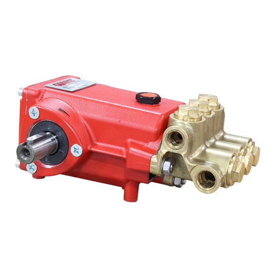
Triplex Ceramic Operating Instructions/ Models Manual P55W/P56W/P56W-HK/P56HT Contents: Installation Instructions: page 2 Pump Specifications: pages 3-5 Exploded View: page 6 Parts List: page 7 Kits: page 8 Trouble Shooting: page 9 Repair Instructions: page 10-13 Pump Mounting Selection Guide: page 14... -
Page 2: Installation Instructions
50 hours of operation, then at regular 4. Run the pump dry approximately 10 seconds intervals of 500 hours or less depending on operat- to drain the water before exposure to freezing ing conditions. temperatures. NOTE: Contact Giant Industries for Service School Information. Phone: (419)-531-4600. -
Page 3: Pump Specifications: Pages
The desired pressure is achieved by selecting the use the following formula: correct nozzle size that corresponds with the pump GPM. GPM X PSI 1460 P55W PULLEY SELECTION & HORSEPOWER REQUIREMENTS PUMP MOTOR RPM GPM 500 PSI 1000 PSI 2000 PSI 2320 PSI PULLEY PULLEY 7.75"... - Page 4 Specifications Models P56W / P56W-HK Ratings (Continuous) ........ 6.1 GPM ( 23 lm) @ 1900 PSI (131 bar) @ 1420 RPM Ratings (Intermittent) ........ 6.0 GPM (23 lm) @ 2200 PSI (152 bar) @ 1750 RPM Ratings (Intermittent) ........7.5 GPM (28 lm) @ 1000 PSI (69 bar) @ 1750 RPM Inlet Pressure ..................
- Page 5 Specifications Models P56HT 750 RPM @ 220 F (104 Ratings ....................193 GPH (730 lh) (3.2 GPM) 900 RPM @ 195 F (91 Ratings ....................233 GPH (882 lh) (3.9 GPM) Discharge Pressure ................. 900 PSI Plunger Diameter ..................20mm Stroke .....................
-
Page 6: Exploded View
Exploded View - P55W / P56W / P56W-HK / P56HT... -
Page 7: Parts List
P55W / P56W / P56W-HK / P56HT PARTS LIST ITEM PART DESCRIPTION QTY. ITEM PART DESCRIPTION QTY. 07180 Crankcase 07369 Manifold Head 07181 Oil Filler Cap with Gasket 07010 Pressure Ring, P55W 07182 Gasket, Oil Filler Cap 07221 Pressure Ring, P56W... -
Page 8: Kits
P55W / P56W / P56W-HK / P56HT REPAIR KITS Plunger Packing Kit, P55W, #09088 Ceramic Plunger Kit P55W, #9539 Item Part # Description Qty. Item Part # Description Qty. 07021 Ceramic Plunger, 18mm 07011 V-Sleeve 08456 Tension Screw Plunger Packing Kit, P56W, #09037... -
Page 9: Trouble Shooting
P55W / P56W / P56W-HK PUMP SYSTEM MALFUNCTIONS MALFUNCTION CAUSE REMEDY The Pressure and/ Worn packing seals Replace packing seals or the Delivery Broken valve spring Replace spring Drops Belt slippage Tighten or Replace belt Worn or Damaged nozzle Replace nozzle... -
Page 10: Repair Instructions
P55W / P56W / P56W-HK REPAIR INSTRUCTIONS NOTE: Always take time to lubricate all metal and nonmetal parts with a light film of oil before reassembly. This step will ensure proper fit, at the same time protecting the pump nonmetal parts (i.e., the elastomers) from cutting and scoring. - Page 11 9. If pitted or worn, replace inlet valve seats (36), valve plates (37), springs (35) and spring retainers (34). Re-insert items 34-38 into valve adapter (39). Install valve assembly (34-40) into manifold (29). Reinstall 10.The rear v-sleeve housing manifold plugs (43) and torque plugs to 50 ft.-lbs. (48) may be removed by prying evenly outward with a flat screwdriver.
- Page 12 25. Insert the far side crankshaft oil seal (14) with the Giant Bearing Tool making sure it is firmly seated and well oiled. Always make sure that the crankshaft seal lip does not show signs of wear and that the garter spring is firmly in place on the seal before reinserting into the pump.
- Page 13 See instructions above for re-installing fluid end onto the gear end. 31. Fill the P55W / P56W crankcase (1) with 14 oz. of Giant Industries’ oil and check the oil level with the dipstick (5). Proper level is center of two lines. Reinstall the pump into your system.
-
Page 14: Pump Mounting Selection Guide
01055 - 9.75” Cast Iron - 2 gr.-AB Section (L=9.00” x W=2.12” x H=2.50” ) 01061 - 7.75” Cast Iron 1 gr. - AB Section 01062 - 7.75” Cast Iron - 2 gr. - AB Section P55W / P56W / P56W-HK / P56HT TORQUE SPECIFICATIONS Position Item# Description... - Page 15 P55W / P56W / P56W-HK / P56HT DIMENSIONS - INCHES (mm)
- Page 16 Liability under this warranty is on all non-wear parts and limited to the replacement or repair of those products returned freight prepaid to Giant Industries which are deemed to be defective due to workmanship or failure of material. A Returned Goods Authorization (R.G.A.) number and completed warranty evaluation form is required prior to the return to Giant Industries of all products under warranty consideration.
Need help?
Do you have a question about the P55W and is the answer not in the manual?
Questions and answers