Table of Contents
Advertisement
Advertisement
Table of Contents

Related Manuals for TOHATSU VE 1500


Summary of Contents for TOHATSU VE 1500
- Page 2 Copyright © 2016 Tohatsu Corporation. All rights reserved. No part of this manual may be reproduced or transmitted in any from or by any means without the express written permission of Tohatsu Corporation.
- Page 3 APPLICATIONS OF THIS FIRE PUMP USAGE TOHATSU fire pump “VE1500 / VE1000” are manufactured for use in fire fighting operations. These portable fire pumps are intended only for fire fighting activities in collaboration with general public fire extinguishing equipment. Using it for other applications is regarded as being used for improper purposes.
- Page 4 Intended people All persons who operate, service or maintain this fire pump must read and understand the following items: • Owner’s manual • Safety-related instructions on the pump and the other parts such as the battery. • The other owner’s manuals, such as battery charger. The portable pump should be operated by only persons who received training as operators of fire engines along with each country’s (region’s) regulations.
- Page 5 INTRODUCTION Thank you for purchasing the TOHATSU Fire Pump. This fire pump has passed a range of quality assurance standards. Owner’s manual This portable fire pump complies with relevant laws and regulations. This manual includes a description for operation and maintenance. Before using this fire pump, be sure to read and understand this manual thoroughly.
- Page 6 MANUFACTURER AND AFTER-SALES SERVICE ADDRESS Before using this fire pump, write down the serial number in the following boxes. This will be useful when you inquire about servicing, repairs, or genuine parts. TOHATSU CORPORATION Address : 3-5-4 Azusawa, Itabashi-ku, Tokyo, JAPAN...
- Page 7 GENERAL SAFETY INFORMATION Overview Before operating the TOHATSU fire pump thoroughly read this manual. Understanding proper operating procedures including “DANGER”, “WARNING”, “CAUTION” and “NOTE”. These notices designed to bring attention to very important information necessary to ensure safe, trouble free operation.
- Page 8 Safety-related instructions and warning signs Read and follow the safety-related instructions described in this manual and all warning signs on the portable fire pump thoroughly. Always keep the warning signs in a legible condition. If any warning sign becomes illegible or detached, replace it immediately.
- Page 9 Emissions Noise emission values For noise emission values, refer to “CONTENT 17 APPENDIX”. Wear proper hearing protection CAUTION during operation. Exhaust gas Exhaust gas emitted from the engine contains carbon monoxide (CO) etc. that may seriously affect human health. Do not operate the engine in a room, car, warehouse, tunnel, or other closed locations that have poor ventilation.
- Page 10 Safety devices Before operating this portable fire pump, be sure to check that all the safety devices have been installed in the appropriate positions. Before removing the safety devices, turn the main switch off. Protective clothing Protective equipment During fire extinguishing training or normal fire fighting services, wear normal protective clothing and equipment to protect your body.
- Page 11 Safety devices After protective devices (such as the muffler guard) have been disassembled as part of servicing and maintenance work, immediately install them back to their original locations, making sure that they are in safe and secure condition. Check portable fire pump visually and...
- Page 12 Use a fuse with the same specifications as the original one when replacing it. Using a fuse that has a greater capacity than the rated value may damage the equipment. Check the electrical equipment of the fire pump on a regular basis. Battery Follow any safety-related instructions shown on the battery.
- Page 13 Genuine parts When replacing parts for servicing and maintenance of the portable fire pump, only use Tohatsu genuine parts. If genuine Tohatsu parts and accessories are not used it may adversely affect the functioning and safety of the fire pump. Use genuine Tohatsu parts only.
- Page 14 If any problems occur during servicing and maintenance work of the portable fire pump, contact our Customer Service. Address : 3-5-4 Azusawa, Itabashi-ku, Tokyo, JAPAN : +81-3-3966-2951 Phone : Service +81-3-3966-3380 / Email tohatsu-pservice@tohatsu.co.jp Overseas section fire protection sales department +81-3-3966-3137 bousaiex@tohatsu.co.jp...
- Page 15 EC Declaration of Conformity (DoC) This product conforms to certain portion of the European Parliament directive. DoC contains the following information; • Name and Address of the manufacturer • Applied community directives • Reference standard • Description of the product (Model name and serial number) •...
-
Page 16: Table Of Contents
CONTENTS 1 SPECIFICATIONS……………….……...…………………… 2 OPERATING DEVICE………….………….…..……………5 3 LABELS…….……………………….…...……………………9 4 OPERATING PRECAUTIONS………..……….…...….…10 5 DESCRIPTION OF DEVICES…….………………….….12 6 PREPARATION FOR OPERATION…….…………….…20 7 USE OF OPERATION PANEL………..…………………24 8 STARTING THE ENGINE…..………………….…..…27 9 PRIME AND DISCHARGE…….………….………….…..31 10 STOPPING THE ENGINE..…….……………….……..…..37 11 MAINTENANCE AFTER OPERATION….….……….….38 12 MAINTENANCE IN COLD CONDITIONS….……….…43 13 USE OF ACCESSORIES………….….……………….…46 14 PERIODICAL INSPECTION………..………..…….……..49... -
Page 17: Specifications
P alim Max. water temperature +60 °C Temperature range -15 °C to +40 °C ambient temperature Engine Manufacturer TOHATSU CORPORATION Model 2WT81A Type 2-stroke, water cooled spark ignition engine Bore × Stroke 81 mm × 78 mm Number of Cylinder... - Page 18 1 SPECIFICATIONS Model VE1500 VE1000 Primer Type Rotary-vane vacuum pump (Oil less type) Max. suction height Approx. 9m Pump Type Single suction, single stage, centrifugal pump Number of delivery outlet Discharge port coupling BSP thread 2-1/2” (65mm) male Suction port coupling BSP thread 4”...
- Page 19 1 SPECIFICATIONS Performance Curve (VE1500)
- Page 20 1 SPECIFICATIONS Performance Curve (VE1000)
-
Page 21: Operating Device
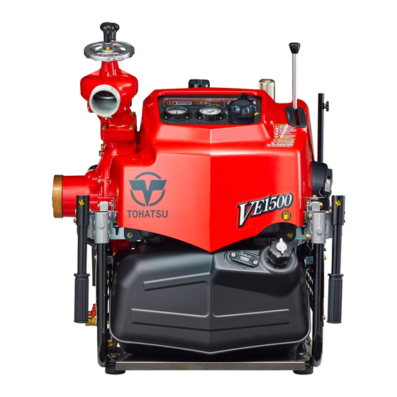
2 OPERATION DEVICE ⑦ ⑦ ⑧ ⑥ ⑨ ⑥ ⑩ ⑤ ⑤ ④ ① ② ③ ① Suction port ② Inducer ③ Impeller ④ Starter motor ⑤ Crankshaft ⑥ Piston ⑦ Spark plug ⑧ Cylinder drain valve ⑨ Pump drain valve ⑩... - Page 22 2 OPERATION DEVICE ⑥ ⑥ ⑤ ⑦ ④ ⑧ ① ② ③ ① Air silencer ② Fuel tank ③ Muffler ④ ECU ⑤ Oil tank ⑥ Discharge valve ⑦ Fuel feed pump ⑧ Injector...
- Page 23 2 OPERATION DEVICE handle Discharge valve Oil tank cap Floodlight Cowl Discharge port Cowl mounting bolt Suction port Fuel tank cap Muffler guard Fuel level gauge ① ② ③ ① Cylinder drain valve ② Pump drain valve ③ Muffler drain valve...
- Page 24 2 OPERATION DEVICE Priming lever Priming strainer Floodlight connector Fuse Manual starter handle Battery charger socket Exhaust pipe Carrying handle Priming outlet Muffler Thermo valve outlet ④ ① Hour meter ② Battery voltage low warning lamp ③ Overheat warning lamp ④...
-
Page 25: Labels
3 LABELS Instruction Warning Caution Warning Warning Warning CE label... -
Page 26: Operating Precautions
OPERATING PRECAUTIONS Installing pump The fire pump must be installed on level ground. Otherwise, CAUTION an accident may occur. If the fre pump should be installed on uneven ground, it must be secured. • Place the pump as near as possible to water source, and water NOTE suction height as low as possible. - Page 27 OPERATING PRECAUTIONS When installing the portable pump in the vehicle, to equip CAUTION with the pump in the vehicle placed on a level place. When installing the portable pump in the vehicle, make sure to apply the brakes of the vehicle in order to stop the wheels. A serious accident may occur if the vehicle moves.
-
Page 28: Description Of Devices
5 DESCRIPTION OF DEVICES Suction port The diameter of the thread for fire pump ① is BSP thread 4” (100 mm). ① When the pump is run while the strainer is not installed, if you insert your finger into the suction port, you may be seriously injured by the rotating inducer. - Page 29 5 DESCRIPTION OF DEVICES ⑥ Carrying handle This fire pump is equipped with four carrying handles ⑥. The handles can be manually folded, and opened by rotating them by 90 degrees. ⑥ Personal injuries may occur CAUTION when opening or closing the handle.
- Page 30 5 DESCRIPTION OF DEVICES Drain valve Use the drain valves to drain water. Close all the valves when operating NOTE this fire pump. If a valve is opened, water cannot ⓐ be suctioned. ⓑ ⓒ ⓐ Cylinder drain valve ⓑ Pump drain valve ⓒ...
- Page 31 5 DESCRIPTION OF DEVICES Control pane The control panel is equipped with all the necessary operating and control instruments as follows. Throttle dial Use the throttle dial ⑫ to control discharge pressure. “ ” indicates the throttle position of engine start and priming.
- Page 32 5 DESCRIPTION OF DEVICES The monitor indicates the following information: • Hour meter • Low engine oil level warning • Overheat warning • Low battery warning Hour meter Hour meter ⑯ indicates the accumulated operation time of the fire pump. ⑯...
- Page 33 5 DESCRIPTION OF DEVICES ⑱ Overheat warning If overheat is detected, overheat lamp ⑱ lights up, the warning buzzer sounds and the engine stops automatically. The engine stops automatically NOTE when an overheat is detected. CAUTION The engine may be damaged. Do not restart the engine soon after it has stopped running.
- Page 34 5 DESCRIPTION OF DEVICES Governor case The governor oil level can be checked with the dipstick ⓐ. ⓐ Use the engine oil recommended by the engine manufacturer. Be sure to stop the engine CAUTION before checking the oil level. If you pull the dipstick when the Governor oil filler pump is being operated, the oil...
- Page 35 5 DESCRIPTION OF DEVICES Thermostat on the pump case When the water temperature in the pump rises above 50°C during closed discharge valves operation after priming water, the thermostat ⓒ installed on the pump case opens to discharge high-temperature water for prevention of water temperature rise. When performing closed...
-
Page 36: Preparation For Operation
6 PREPARATION FOR OPERATION Initial charge of battery The battery can be used immediately after filling cells with electrolyte. If the battery is maintenance free of electrode(Sealed type battery), do not open the battery after filling it with electrolyte. Refer to the INSTRUCTIONS the battery. - Page 37 6 PREPARATION FOR OPERATION NOTE Use of low-quality fuel results in a short engine life as well as starting difficulty other engine Fuel problems. Fuel containing alcohol, methanol (methyl), or ethanol (ethyl), may cause: ・ Deterioration of rubber parts and plastic parts.
- Page 38 6 PREPARATION FOR OPERATION Engine oil Refill the 2-stroke engine oil to the oil tank. Engine If different grades of engine CAUTION oil are mixed, the oil may gelate, which may result in oil filters becoming clogged. Be sure to use the same grade of engine oil.
- Page 39 6 PREPARATION FOR OPERATION CLOSE Discharge valves Make sure the discharge valves are closed. Overheat protection sensor This device shuts down engine automatically when the engine has excessively overheated caused by lack of cooling wat Overheat warning lamp If the temperature of the cooling water reaches approximately 90ºC or more, the engine will be stopped automatically to prevent overheating.
-
Page 40: Use Of Operation Panel
7 USE OF OPERATION PANEL Alert action check NOTE When the power is turned ON, the warning lamp and buzzer will be activated for approximately one second, and the alert action check is automatically performed. After that, the installed computer starts monitoring. Set the main switch to the”... - Page 41 7 USE OF OPERATION PANEL Engine Running Restart status Light & Buzzer 80°C Engine can start at less than 120°C and Over- Engine 90°C keep running for 30 seconds. heating STOP Light & Buzzer 70°C Over Engine Engine cannot start 120°C STOP Remedy...
- Page 42 7 USE OF OPERATION PANEL Hour Meter Before removing the electrical equipment, turn the main switch off and remove the battery. When removing the battery cable from the battery terminal, always disconnect negative (-) cable first. When connecting battery cables, connect the positive (+) lead first.
-
Page 43: Starting The Engine
8 STARTING THE ENGINE Pump Installation Since the temperature around the engine becomes high because of the muffler and exhaust gas, install the pump on level ground at least three meters away from inflammable materials including dead leaves and wood. Exhaust gas, which... - Page 44 8 STARTING THE ENGINE Starting engine Remove air from the fuel line Before initially fueling this portable pump or restarting the engine after the engine stopped due to lack of gas, bleed air from the fuel line. ① 1. Turn the main switch from the “...
- Page 45 8 STARTING THE ENGINE Starting engine 1. Check that the air vent ② of the fuel tank is closed. ② 2. Set the throttle dial ③ at “ ” mark position. ③ 3.Turn the main switch ④ to “ ” position. Release the main switch ④...
- Page 46 8 STARTING THE ENGINE Dry operation This portable pump has an outsource cooling system, limit the duration of dry operation so that it is within the following time periods. Performing dry operation longer than the specified time period may cause damage to the engine or pump.
-
Page 47: Prime And Discharge
9 PRIME AND DISCHARGE While the engine is running with the cowl removed, do not touch the rotating parts of the pulley or belt. This may cause personal injuries. If, when operating the vacuum pump for 30 seconds, the pump NOTE does not suck water, or if the pump cannot keep the water in it during the water discharge operation, check the following:... - Page 48 9 PRIME AND DISCHARGE Limit the vacuum pump operating time within 30 seconds. If the NOTE pump cannot suction water within 30 seconds, it may have been caused by another problem. Refer to “CONTENT 16 TROUBLE SHOOTING” to rectify the problem OPEN 4.
- Page 49 9 PRIME AND DISCHARGE Performing relayed water supply (when sucking water from fire hydrant) 1. Determine the pump pressure in consideration of the water discharge pressure (nozzle pressure), hose pressure (friction) loss, and height loss. Pump pressure = needed pressure + height loss + friction loss 2.
- Page 50 9 PRIME AND DISCHARGE Relay pumping operations Discharge port adaptor In the case of relay pumping CAUTION operations training in a flat place, number extending hose is less than Packing ten, use the Safety nozzle attached. Pumping plate (Standard accessory) Part No.151-39045-1 Description of relay pumping operation...
- Page 51 9 PRIME AND DISCHARGE Preparation for operation Never close the discharge valve of source pump and the relay pump(s), and the fire nozzle(s). If the discharge valves or nozzle is(are) closed, there will be a risk of damage to the pumps and hoses with excessive pressure or water hammer.
- Page 52 9 PRIME AND DISCHARGE 3. If it becomes clear that water was supplied to the pump, check the pressure of the gauge. Start the engine when it is lower than the decided pressure. If the pressure is higher than the decided pressure, no need to start the engine. 4.
-
Page 53: Stopping The Engine
10 STOPPING THE ENGINE Do not touch the exhaust pipe and the CAUTION muffler while the engine is running, or for 10 minutes after the engine has been stopped. These parts are very hot and will cause severe burns. 1. Return the throttle dial to “ ”... -
Page 54: Maintenance After Operation
11 MAINTENANCE AFTER OPERATION Maintenance after pumping seawater or foul water After pumping seawater or foul water, the pump should be flushed out with fresh water immediately to prevent excessive corrosion. And operate the vacuum pump for 5 seconds at low engine speed (“ ” position) in order to clean the vacuum pump. Drain water 1. - Page 55 11 MAINTENANCE AFTER OPERATION 3. Start the engine, and operate the priming lever with the throttle dial in the “ ” position to produce a vacuum (within 30 seconds). 4. After a vacuum is produced, immediately return the priming lever to the original position, and stop the engine.
- Page 56 11 MAINTENANCE AFTER OPERATION Fuel / Oil Supply 1. Fuel Fill fuel until the maximum level of the gauge Indicator (in red). • Fuel tank capacity : 24L Do not tilt the pump with the air CAUTION vent open. Otherwise, the fuel may leak.
- Page 57 11 MAINTENANCE AFTER OPERATION Cleaning strainer for prime Ring nut Remove the ring nut and clean the strainer with fresh water. If the strainer is dirty with dust, etc., vacuum performance efficiency will be reduced. O-Ring When assembling the strainer, NOTE Strainer tighten the ring nut while holding...
- Page 58 11 MAINTENANCE AFTER OPERATION Battery charger ・Use an automatic battery charger. CAUTION (A battery charger that automatically switches to the trickle charging mode when recovery charging has been completed) Charging current when recovery charging is carried out:1.8 A or below Charging current when trickle charging is carried out: 20 mA or below ・Use a maintenance-free (MF) battery.
-
Page 59: Maintenance In Cold Conditions
12 MAINTENANCE IN COLD CONDITION Infuse anti-freezing fluid If the temperature around the pump could be subzero, the CAUTION pump inside may freeze up. It may cause not only the damage in the pump, but also the inability to start the engine. For pump unit 1. - Page 60 12 MAINTENANCE IN COLD CONDITION 7. After starting the engine, pull down the priming lever. 8. Be sure the pressure gauge shows positive side. Even anti-freezing fluid NOTE disappears, continue pulling priming lever for 30 seconds. By this operation, anti-freezing fluid reaches every part of the pump 9.
- Page 61 12 MAINTENANCE IN COLD CONDITION When you install a strainer, pay attention to the protrusion of the NOTE O-ring and install it correctly. Otherwise, a vacuum leak may occur. When installing a strainer, tighten the ring nut while pressing the cup with your palm. When installing the strainer, exercise care so that the O-ring CAUTION does not get caught in, and tighten the ring nut securely.
-
Page 62: Use Of Accessories
13 USE OF ACCESSORIES Battery Battery performance deteriorates if the temperature decrease. Further, battery may freeze if the specific gravity is low. ・ When charging batteries, be sure to use CAUTION an automatic battery charger dedicated to sealed batteries. ・ Use an automatic battery charger that matches the battery specifications. - Page 63 13 USE OF ACCESSORIES Pumping plate When the pump is operated using a discharge CAUTION nozzle that has a nozzle diameter greater than the maximum nozzle diameter, or without using a discharge nozzle, be sure to use the pumping plate. The pump may break down due to cavitation or may overheat due to lack of cooling water.
- Page 64 13 USE OF ACCESSORIES Detachable exhaust hose <Specification> ・Inside diameter: φ50 ・Length: 1500 mm ・Standard: EN 14466 : 2005 Annex C Do not touch the detachable exhaust hose CAUTION because it becomes hot during operation. Do not operate the pump if it has been placed combustible materials...
-
Page 65: Periodical Inspection
14 PERIODICAL INSPECTION Perform periodical inspections and maintenance according to the following procedures. Inspection intervals Description Inspection items Measure Impurities ● Clean (ie. Water and / or waste) Replace *1 ・ Including High Fuel filter Impurities (If water pressure filter ●... - Page 66 14 PERIODICAL INSPECTION Inspection intervals Description Inspection items Measure Wear, crack, belt ● V-Belt Replace *1 tension Clogged or broken ● Strainer Clean or replace mesh Priming ・ Is not locked system ・ Check Replace parts if ● necessary *1 performance Primer (-0.8 bar)
-
Page 67: Service And Maintenance
15 SERVICE AND MAINTENANCE General Servicing and maintenance of this fire pump must only be carried out by personnel who have professional related knowledge and who are familiar with this fire pump and regulations regarding safety and accident prevention. Before starting maintenance work: ・... - Page 68 When replacing parts as part of servicing and maintenance of this fire pump, use only Tohatsu genuine parts. If genuine Tohatsu parts and accessories are not used it may adversely affect the functioning and safety of the fire pump. Therefore, for safety reasons, use only Tohatsu genuine parts.
- Page 69 15 SERVICE AND MAINTENANCE Cowl removal and installation Top cowl removal 1. Remove the mounting screw on the manual starter side. 2. Pull the cowl hook (front side 2 pieces), lift cowl slowly. Remove cowl carefully CAUTION without coming in contact with priming lever discharge valve.
- Page 70 15 SERVICE AND MAINTENANCE Vacuum pump strainer Maintenance Incorrect installation of the strainer NOTE may cause a vacuum leak. Be sure to install the strainer correctly. Wash the strainer ① with fresh water after each use. turn 1. On the occasion of washing the strainer, the ring nut ②...
- Page 71 15 SERVICE AND MAINTENANCE Governor oil Check the governor oil Check every three months or every 50 hours, operating time. 1. Place the pump on a level location. 2. Remove the oil dipstick ① , wipe it with a cloth. 3.
- Page 72 15 SERVICE AND MAINTENANCE Spark plug Check the spark plugs 1. Remove the plug caps, and remove the spark plugs①. 2. Use a wire brush or spark plug cleaner, clean the ② electrode of the spark plug 3. Check the spark plug for excessive carbon depos its, electrode ②...
- Page 73 15 SERVICE AND MAINTENANCE Battery General safety information Battery Follow the safety instructions on the battery. When charging batteries, highly explosive oxyhydrogen gas mixture is produced. Never charge a battery in a poorly ventilated place. Do not smoke near the battery. Danger of injury due to caustic substances of battery.
- Page 74 15 SERVICE AND MAINTENANCE Electric equipment Only expert electricians or trained staff members should handle electrical equipment. Be sure to disconnect battery cables before handling electrical equipment. Disconnect the negative terminal first, and then disconnect the positive terminal. When connecting battery cables, connect the positive terminal first, and connect the negative terminal.
- Page 75 15 SERVICE AND MAINTENANCE Vacuum performance check Limit continuous operating time of the vacuum pump to CAUTION 30 seconds or less. Operating the pump for 30 seconds or more continuously may cause the engine to overheat. If the engine overheats, wait until it cools down, or perform the water discharge operation.
- Page 76 15 SERVICE AND MAINTENANCE Vacuum leak check After completing the vacuum performance check, monitor the suction pressure indicated with the suction gauge for approximately 30 seconds to check for vacuum leaks. the “ CONTENT 16 If a vacuum leak is found, isolate the cause by referring to TROUBLESHOOTING”.
-
Page 77: Troubleshooting
16 TROUBLESHOOTING Typical causes of engine troubles are listed in the following tables. Trouble Action Cause ● ● ● ● Low fuel Refuel. Deterioration Replace with new ● ● ● ● ● ● of fuel fuel. Fuel tank air ● ● ● ●... - Page 78 16 SERVICE AND MAINTENANCE Trouble Action Cause Spark plug cap ● ● ● ● ● Plug in surely. comes off Replace with Use of unspecified ● ● ● ● ● ● ● specified spark spark plug plug. Spark plug fouling Clean or replace with ●...
- Page 79 16 SERVICE AND MAINTENANCE Trouble Action Cause Replace with spare fuse. When the blowout of ● ● 15A fuse blown the fuse happens repeatedly, check a cause. 15A: Battery cable reverse connection, operation panel components and search light ● 5A fuse blown connector 5A: Charging connector...
- Page 80 16 SERVICE AND MAINTENANCE Trouble Action Cause Piston, piston ● ● ● ● ● ● ring or cylinder Correct or replace. excessively worn. Carbon deposition ● ● ● ● Clean out. in the combustion chamber Suction height too Place the pump to ●...
- Page 81 16 SERVICE AND MAINTENANCE Trouble Action Cause Tighten securely a Vacuum pipe loose ● ● clump of vacuum pipe or cracking or replace. Tighten securely or Strainer cap loose ● ● or O-ring failure replace. V belt damaged ● ● Replace.
- Page 82 16 SERVICE AND MAINTENANCE Trouble Action Cause Three drain valves ● ● ● Close securely. are not closed Suction port strainer clogged ● ● Clean out. with dead leaves or waste etc. Discharge valve ● ● Open securely. imperfect open Gauge pipe Tighten securely.
- Page 83 16 SERVICE AND MAINTENANCE Trouble Action Cause Change the nozzle Discharge nozzle for suitable size or ● ● ● too large Incorporate safety nozzle. Spray nozzle ● Clean out. clogged Governor ● ● ● Adjust it securely. adjustment out of specified range Governor link ●...
-
Page 84: Appendix
17 APPENDIX Noise Emission Level Machine Model: VE1500 Operating condition: According to EN14466 ANNEX E E.5 and ISO20361Clause 8 Other information: See each test results Declared DUAL-NUMBER Noise Emission Values A-weighted Emission Sound Pressure Level: 97 dB(A) at the operating position; 2.5 dB(A) Uncertainty K Measured A-weighted Sound Power Level:... -
Page 85: Tools And Standard Accessories
18 TOOL AND STANDARD ACCESSORY Standard accessory Description Parts No. Quantity Tool kit 151-39010-2 • Tool kit bag • Plug wrench • Handle of plug wrench Spark plug (BPR7HS-10) 9701-1-1014 Pumping plate 151-39045-1 Fuse *15A 3T5-76246-0 Fuse *5A 1K9-76243-0 Vinyl pipe 1H0-31569-0 Search Light (4P) 1H9-39020-0... -
Page 86: Wiring Diagram
19 WIRING DIAGRAM... -
Page 87: Transporting Device
TRANSPORTING DEVICE MANUAL The TRANSPORTING DEVICE (TRANSPORT FRAME KIT) consists of the following parts. You can reorder only the parts having part numbers. Check the part numbers, and order them to Tohatsu Corporation. Figure Part name Part number Quantity... - Page 88 20 TRANSPORTING DEVICE MOUNTING STRUCTURE AND MOUNTING METHOD ・ Be sure to assemble this frame on a flat and level place. CAUTION ・The frame should be assembled by two or more persons. 1. Remove the damper rubbers from the bottom of the pump frame.
Need help?
Do you have a question about the VE 1500 and is the answer not in the manual?
Questions and answers