
Related Manuals for TOHATSU VF53AS


Summary of Contents for TOHATSU VF53AS
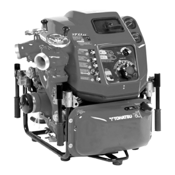
- Page 1 TOHATSU PORTABLE FIRE PUMPS OWNER’S MANUAL Model VF53AS, VF63AS-R Original instructions TOHATSU CORPORATION Date of print:(2018.02) Date of publication:(2018.02) 003-12076-0 AH1...
- Page 2 Copyright@2016 Tohatsu Corporation. All rights reserved. No part of this manual may be reported or transmitted in any from or by any means without the express written permission of Tohatsu Corporation.
- Page 3 APPLICATIONS OF THIS FIRE PUMP USAGE TOHATSU portable fire pump ” VF53AS and VF63AS-R” are manufactured for use in fire fighting operations. The portable fire pumps are intended only for fire fighting activities in collaboration with general public fire extinguishing equipment.
- Page 4 Intended people All persons who operate, service or maintain the fire pump must read and understand the following items: ・Owner’s manual ・Safety-related instructions on the pump and the other parts such as a battery. ・The other owner’s manuals, such as a battery charger. The portable fire pump should be operated by only persons who received training as operators of fire engines along with each country’s (region’s) regulations.
- Page 5 INTRODUCTION Thank you for purchasing the TOHATSU Fire Pump. This fire pump has passed a range of quality assurance standards. Owner’s manual The portable fire pump complies with relevant laws and regulations. The manual includes descriptions for operation and maintenance. Before using the fire pump, be sure to read and understand the manual thoroughly.
- Page 6 MANUFACTURER AND AFTER-SALES SERVICE ADDRESS Before using the fire pump, write down the serial number in the following boxes. This will be useful when you inquire about servicing, repairs, or genuine parts. TOHATSU CORPORATION Address : 3-5-4 Azusawa, Itabashi-ku, Tokyo, JAPAN : +81-3-3966-2951 Phone...
- Page 7 GENERAL SAFETY INFORMATION Overview Before operating the TOHATSU fire pump thoroughly read the manual. Understanding proper operating procedures including “DANGER”, “WARNING”, “CAUTION” “NOTE”. These notices are designed to bring attention very important information necessary ensure safe, trouble free operation. Warning sign meaning...
- Page 8 Transporting the portable fire pump Retractable handle is folding ・ CAUTION type. Do not put a hand or finger ・ between top of th e retractable handle and bracket. When transporting the portable ・ fire pump, assign one person per handle.
- Page 9 Handling of fuel Exercise care when handling fuel. Failure to do so may cause fire. Do not bring any flames near fuel. Stop the engine before refilling fuel. Do not smoke while refilling fuel. Do not refill fuel in an enclosed room to avoid an explosion by fuel fumes.
- Page 10 Service and Maintenance Servicing and maintenance of the fire pump must be carried out by o n l y t h e persons who have professional knowledge, who are familiar with the device, and who understand laws and regulations regarding safety and accident prevention.
- Page 11 Electrical equipment Only expert electricians trained staff members should handle electrical equipment. When removing the battery cable from the electrical equipment, always disconnect the negative (-) cable first. When installing the battery cable, be sure to connect the positive (+) cable first before connecting the negative (-) Do not place any metal on the top of or around the battery.
- Page 12 Battery Follow any safety-related instructions shown on the battery. The battery can generate flammable hydrogen gas that may cause an explosion. Do not charge the battery in closed location. Do not smoke around the battery. The battery electrolyte is caustic and may cause personal Injuries.
- Page 13 Tohatsu genuine parts. If genuine Tohatsu parts and accessories are not used, it may adversely affect the functioning and safety of the fire pump. Use genuine Tohatsu parts only. Tohatsu bears no responsibility for any personal...
- Page 14 If any problems occur during servicing and maintenance work of the portable fire pump, contact our Customer Service. Address : 3-5-4 Azusawa, Itabashiku, Tokyo, JAPAN : +81-3-3966-2951 Phone : Service +81-3-3966-3380 Email : tohatsu-pservice@tohatsu.co.jp Overseas section fire protection sales department +81-3-3966-3137 bousaiex@tohatsu.co.jp...
-
Page 15: Table Of Contents
CONTENTS SPECIFICATION ....................1 OPERATING DEVICE ..................4 LABELS ......................7 OPERATING PRECAUTION ................ 8 DESCRIPTION OF DEVICE ............... 10 PREPARATION FOR OPERATION.............. 22 USE OF CONTROL PANEL ................26 STARTING THE ENGINE ................34 PRIME AND DISCHARGE ................38 STOPPING THE ENGINE ................ -
Page 16: Specification
SPECIFICATION Model VF53AS VF63AS-R 1 1 Description Portable fire pump Engine 2 2 Manufacturer TOHATSU CORPORATION Model 3WF61A 3 3 Type 4-stroke, EFI 4 4 Bore × Stroke 61 mm × 60 mm Number of Cylinder 5 5 Piston displacement... - Page 17 SPECIFICATION Model VF53AS VF63AS-R 1 1 Primer Type Rotary-vane vacuum pump (Automatic suction) 2 2 Max. suction height Approx. 9 m (29.5 ft.) 3 3 Pump Type Single suction, single stage, turbine pump 4 4 Number of delivery outlets*1 5...
- Page 18 SPECIFICATION Performance Curve 1 1 2 2 3 3 4 4 5 5 6 6 7 7 8 8 9 9...
-
Page 19: Operating Device
OPERATING DEVICE VF53AS 1 1 2 2 3 3 Manual starter handle Pressure gauge 4 Warning lamp 4 Vacuum gauge 5 5 Top cowl 6 6 Bottom cowl 7 7 Auto priming switch Main switch Throttle dial 8 8 Engine oil tank Manual suction 9... -
Page 20: Operating Device
OPERATING DEVICE VF53AS 1 1 2 2 3 3 4 4 5 5 Screw down valve type Discharge valve Ball valve type 6 6 7 7 8 8 9 9 Discharge valve’s drain Latch Cooling water strainer (for top cowl) - Page 21 OPERATING DEVICE VF63AS-R 1 1 2 2 3 3 Different operation part from VF53AS 4 4 5 5 Operation Priming water 6 6 mode switch mode switch 7 7 8 8 9 9 Stop switch Warning lamp Control panel Main/Start...
-
Page 22: Label
LABEL 1 1 2 2 3 3 4 4 Label Instruction label Danger : Fuel 5 5 Warning : Exhaust gas 6 6 7 7 8 8 9 9 Operation procedure label... -
Page 23: Operating Precaution
OPERATING PRECAUTION Installing pump 1 1 ・The fire pump must be installed on level ground. ・Otherwise, an accident may occur. 2 2 ・If the fire pump should be installed on uneven ground, it must be secured. 3 3 ・Place the pump as near as possible to water source, and NOTE 4... - Page 24 OPERATING PRECAUTION ・When installing the portable pump in a vehicle, place CAUTION the vehicle on a level place, and install the pump. 1 1 ・ When installing the portable pump in the vehicle, 2 make sure to apply the brakes of the vehicle in order 2...
- Page 25 DESCRIPTION OF DEVICE Carrying handle Carrying handle 1 1 The fire pump is equipped with four carrying handles. The handles can be manually folded, and 2 2 opened by turning them by 90 degrees. 3 3 Carrying handle 4 4 ・...
-
Page 26: If You Insert Your Finger Into The
DESCRIPTION OF DEVICE Assembling cowl 1 1 Assembling order is in reverse order of the opening. Starter handle ・ Pay attention to have the starter 2 2 handle for manual starting go through the window at the front- upper side of 3... - Page 27 DESCRIPTION OF DEVICE Discharge port 1 1 The diameter of the thread for fire pump is JIS fire thread (B-9912) 2-1/2” (65 mm), 2 2 BSP thread 2-1/2" (65 mm) 3 3 Discharge valve Handle 4 4 Use discharge valve handle for opening and closing the discharge valves.
- Page 28 DESCRIPTION OF DEVICE Priming knob 1 1 ・Use for priming water by manual operation. ・After starting the engine, pull the priming knob to 2 2 suction water. ・ After priming water has been completed, return 3 3 the priming knob to its original position. 4...
- Page 29 Main switch ・ 3 3 T h r o t t l e d i a l ・ ・All warning lamps 4 4 ・Auto priming switch.(VF53AS) Priming water mode switch.(VF63AS-R) 5 5 6 6 Throttle dial Auto priming switch 7...
- Page 30 7 7 continuously when the main switch is at ON position. VF53AS 8 8 In case of oil pressure switch is defective or the Fuel and circuit is disconnected, the warning lamp blinks 9...
- Page 31 In the case of engine stop due to unable suction water complete within 30 seconds in the auto 3 3 priming mode, the warning lamp blinks slowly VF53AS and the warning buzzer sounds continuously. 4 4 In case of TPS,MAT,MAP or WTS is defective or...
- Page 32 DESCRIPTION OF DEVICE Auto priming 1 1 Auto priming switch (VF53AS) In the case of turning on the auto priming switch, VF53AS 2 2 running the engine and turning the throttle to water suction position, the pump starts to suck water.
- Page 33 DESCRIPTION OF DEVICE Cooling water recirculation system 1 1 This system is to recirculate the cooling water without draining outside. Accordingly, the engine does not have a cooling water drain hose. 2 2 Overheat prevention device 3 3 This device monitors the cooling water temperature with a water temperature sensor.
- Page 34 DESCRIPTION OF DEVICE Electric Safety Governor (ESG) 1 1 Designed as a system to assist the mechanical governor, the electric governor controls the maximum engine speed by cutting off ignition so that 2 2 the engine speed does not exceed 6100r/min. Battery save control 3...
-
Page 35: Description Of Device
DESCRIPTION OF DEVICE Fuse box 1 1 Security fuses are installed for electrical circuit in the fuse boxes. 2 2 There are two fuse boxes: -Black color fuse box : 15A fuse. -Yellow color fuse box : 7.5A fuse. 3 3... - Page 36 DESCRIPTION OF DEVICE Floodlight (Option) 1 1 Use the floodlight projector to light up the location where the fire pump operates 2 2 Connect the floodlight plug to the connector. Loosen the adjust screw ① and pull up the floodlight projector ② to 3...
- Page 37 PREPARATION FOR OPERATION Fuel 1 1 Fill the tank with gasoline until the maximum level of the (Red) gauge indication. 2 2 3 3 Fuel tank capacity: 10L (2.6gal(US)) Level gauge 4 4 ・Vaporized fuel may cause ignition or DANGER an explosion.
-
Page 38: Preparation For Operation
PREPARATION FOR OPERATION ・Use of low-quality fuel results in a short engine life as well NOTE as starting difficulty and other engine problems. 1 1 ・ Fuel containing alcohol, methanol (methyl), or ethanol 2 2 (ethyl), may cause: -Deterioration of rubber parts and plastic parts. 3... - Page 39 PREPARATION FOR OPERATION ・If the engine oil is not enough (less than approx. 1/3 of the oil NOTE pan), the warning lamp for oil level lights on, and also the 1 1 warning buzzer sounds. ・If the oil becomes cloudy white, or it is dirty, please consult 2...
- Page 40 PREPARATION FOR OPERATION Discharge valve 1 1 Close the discharge valves and the drain Close valves. 2 2 Screw down discharge valve________ 3 Close 3 4 4 Close 5 5 Ball cock discharge valve __________ 6 6 ・It is possible to lock the direction 7...
- Page 41 USE OF CONTROL PANEL Control Panel 1 1 VF53AS 2 2 Main switch 3 3 Warning lamp ① Warning lamp ② 4 4 Throttle, Suction 5 5 position Throttle dial ⑬ Throttle, 6 6 Start/Low Auto priming pressure switch 7...
- Page 42 USE OF CONTROL PANEL Warning lamp 1 1 Light on: Fuel shortage. Slow blinking: Engine oil pressure reduced. Warning lamp ① 2 2 Fast blinking : Engine oil pressure switch failure. Circuit break. 3 3 Light on: Engine stop due to overheating. Slow blinking: Unable suction water in 30 Warning lamp seconds.
- Page 43 USE OF CONTROL PANEL Pictogram 1 1 Warnings will be also displayed by light on pictograms.(VF63AS-R) ○ Fuel shortage 2 2 Light on : Amount of fuel in the fuel tank is 1/3 or less. ・Refill fuel. 3 3 ○ Engine trouble 4...
- Page 44 USE OF CONTROL PANEL Alarm indication for electronic throttle trouble 1 1 In addition to the standard type warning, VF63AS-R type has warnings for electronic throttle abnormality. 2 2 ○ Warning indication 3 3 ・Warning lamp 1:Slow blinking ・Engine failure warning lamp:Light on 4...
-
Page 45: Use Of Control Panel
USE OF CONTROL PANEL When the warning lamps are all off, there is no problem on each function. * Countermeasures (Warning lamp turns ON) 1 1 It is necessary to take a countermeasure if the lamp lights up when turning the main switch to the “ON”... - Page 46 USE OF CONTROL PANEL When the main switch is turned at the ON position. The engine speed is controlled at 2800rpm. 1 1 a. When the cooling water temperature reaches approximately 90C or higher, the overheat prevention device is actuated and stops the 2...
- Page 47 4 4 restart the engine immediately, engine may be burnt. Before restarting engine, 5 5 eliminate the cause. VF53AS (Refer “Chapter 6 6 TROUBLESHOOTING”) ・ After that, check that the 7 7 warning lamps are turned off.
- Page 48 USE OF CONTROL PANEL ・Precautions for restarting after the overheat prevention device is actuated, 1 1 1. Resolve the cause of the abnormally high cooling water temperature, and then restart the engine. If the cause of the abnormally high cooling water 2...
- Page 49 STARTING THE ENGINE Installation pump 1 1 ・Set the pump on a level ground at least three meters WARNIN away from inflammable materials including dead leaves 2 2 and wood. Because the temperature around the engine becomes high with the muffler and exhaust gas. 3...
- Page 50 Make sure that all the discharge valve(s) is closed. Make sure to turn on the “Auto priming” switch. VF53AS: In the case of the “Auto priming” switch is “ON” position, If water supply Close is not achieved in 30 seconds, then the engine will stop.
-
Page 51: Starting The Engine
STARTING THE ENGINE VF53AS VF53AS 1 1 1. Turn the throttle dial to the “Start” position. Main switch 2 2 2. Turn the main switch to the “ON” position and starts. 3 3 Throttle dial VF63AS-R 4 4 VF63AS-R 1. Turn the throttle dial to “Low pressure”... - Page 52 STARTING THE ENGINE In case of the auto priming switch is ON, the vacuum pump will run automatically. In the 1 1 case of the auto priming switch is OFF, pull the priming knob to prime water. 2 2 3. Pull the manual suction knob, and operate the vacuum pump.
- Page 53 Refer to “Chapter 16 TROUBLESHOOTING”. 1. Once the engine starts, turn the throttle dial to VF53AS the suction position. Main switch 2. The vacuum pump operates automatically until the suction finished (Maximum operating time is for 30 seconds) .
- Page 54 PRIME AND DISCHARGE In the auto priming mode, NOTE ・The vacuum pump runs at around 1800rpm. 1 1 ・If a water cannot be supplied within 30 seconds, the engine will stop automatically. 2 2 ・If the engine speed is lower than 1300 rpm and the vacuum pump is not operated, the engine will stop automatically in 3...
- Page 55 PRIME AND DISCHARGE 6. Checking the pressure at the pressure gauge, Pressure gauge gradually turn the throttle dial to adjust the 1 1 pressure. 2 2 3 3 Throttle dial 4 4 5 5 ・In the case of using a branch pipe, the person holding the CAUTION branch pipe must be notified of changes in water 6...
- Page 56 PRIME AND DISCHARGE Relay pumping water operation 1 1 ・In the case of relay pumping operation training in a flat CAUTION place, if the number of extending hose is less than ten, 2 2 use the safety nozzle attached. 3 3...
- Page 57 PRIME AND DISCHARGE Performing relayed water supply (When having water from fire hydrant) 1 1 1. Decide the pump pressure in consideration of the water discharge pressure (nozzle pressure),height loss and hose pressure loss(friction 2 2 loss). 3 3 Pump pressure = needed pressure + height loss+ friction loss 2.
- Page 58 1. Make sure that the discharge valves and the fire nozzle(s) are all opened. 2. Turn the auto switch on. ・VF53AS: Turn on the auto priming switch. (In the case of choosing the manual mode, priming water must be done by manual.) ・VF63AS-R: Choose the operating mode of stand-alone.
- Page 59 9 9 ・VF53AS: Start the engine run. Check pressure with the pressure gauge. And start the engine when it is lower than the decided pressure. If the pressure is higher than decided pressure, no need to start the engine.
-
Page 60: Prime And Discharge
PRIME AND DISCHARGE ・ If the suction side water pressure goes down below 0.05 MPa(7psi) for about 15 seconds, the pump will stop automatically. 1 1 ・To stop at emergency, press the stop switch. 2 2 *1 Start cycle control ・Standby mode: Switching the pump mode to the relay water supply 3... - Page 61 PRIME AND DISCHARGE ・Discharge water pressure limiter: Throttle position is controlled to make the discharge pressure will not be over about 1 1 1 MPa. ・ Suction water pressure limiter: Throttle position is controlled to 2 2 make the suction water pressure will not be below about 0.15MPa(22psi) to prevent the hose from being 3...
- Page 62 0.1MPa (15 psi) or below. Keep (Operate) the throttle dial not to make the 9 9 suction water side pressure below 0.1MPa (15psi). (VF53AS,VF63AS- R:Stand-alone mode) 7. To finish the discharging water, turn the throttle dial to the low pressure firstly, then stop the engine, and close the fire hydrant on-off valve.
- Page 63 PRIME AND DISCHARGE Control panel operation table 1 1 VF63AS-R Operation mode switch Stop switch 2 2 3 3 4 4 5 5 6 6 7 7 8 8 Start switch (Main switch) 9 9 Power Power Stand- Relay Stand- Relay alone ↓...
-
Page 64: Stopping The Engine
6 6 Close 7 7 8 8 Close 9 9 Close VF53AS 3. Turn off the main switch. VF53AS VF53AS: Turn off the main switch . Main switch VF63AS-R VF63AS-R: Press the stop switch until the engine stops. Stop switch... -
Page 65: Maintenance After Operation
3. Close all the drain valves. ・ Prepare a suction cap that is Suction port cap NOTE suitable for the suction coupling. (VF53AS) Main switch 4-1. Confirm the throttle dial is at “Start” position, and turn on the Auto-priming switch. - Page 66 MAINTENANCE AFTER OPERATION (VF63AS-R) Priming water VF63AS-R 1 1 4-2. Confirm the throttle dial is at “Start” (Low mode switch pressure)position, and press the main 2 2 switch to start the engine. Suction 5-2. Switch the priming water mode to “Auto”. 3...
- Page 67 MAINTENANCE AFTER OPERATION Fuel and Oil 1 1 1. Fuel Fill fuel until the maximum level of the fuel tank. 2 2 The maximum level can be confirmed by the fuel level gauge indicator(Red). 3 3 Level gauge * Fuel tank capacity : 10L (2.67gal(US)) 4...
- Page 68 MAINTENANCE AFTER OPERATION Cleaning strainer for prime 1 1 Remove the strainer and clean it with fresh water. If the strainer is dirty with dust, etc., 2 2 vacuum performance efficiency will be reduced. ・Vacuum pump strainer : 87 mm long 3...
- Page 69 MAINTENANCE AFTER OPERATION Charging battery 1 1 <Battery> ・Read the safety instructions and/or warnings carefully 2 2 before using or charging the batteries. ・Hydrogen gas from the battery is explosive. 3 3 ・Keep battery away from flame and sparks. ・Charge the battery in well ventilated area. Do not charge 4...
- Page 70 Main switch 4. Plug the charging plug to the battery charger plug socket of pump. VF53AS VF63AS-R 5. Insert the power plug of the charger to an alternating current power source. 6. Confirm the battery charging status.
- Page 71 MAINTENANCE IN COLD CONDITION Infuse anti-freezing fluid 1 1 ・If the temperature around the pump could be subzero, CAUTION the inside of the pump can be frozen. In this case, the water pump or the vacuum pump may not be worked. 2...
-
Page 72: Maintenance In Cold Condition
MAINTENANCE IN COLD CONDITION 4. Start engine 1 1 VF53AS (VF53AS) ・Set the Auto-priming switch “ON” position. 2 2 Auto-priming switch 3 3 4 4 5 5 Suction position ・Turn the throttle dial to the “Start” position. 6 6 Start position 7... - Page 73 1 1 Keep the engine running to suck up antifreeze. 2 2 * The engine will stop automatically in about VF53AS 3 3 30 second because of the water suction Suction position failure. 4...
- Page 74 USE OF ACCESSORIES Battery 1 1 Battery performance deteriorates i n a low-temperature condition. Further, battery could be easier to freeze if the specific gravity is low. 2 2 Battery specification Capacity: 16 Ah 3 3 ・Hydrogen gas from a battery is explosive. 4...
-
Page 75: Use Of Accessory
USE OF ACCESSORIES ・Read the instruction manual of the battery charger. The CAUTION instruction manual is packed with the charger. 1 1 ・ Set the battery charger on a suitable noninflammable stand or fix on wall, not directly onto the ground. 2... - Page 76 PERIODICAL INSPECTION Be sure to inspect the fire pump according to the following inspection list. 1 1 Operating Time or Description of Inspection Item Action Remarks Period Inspection 2 2 Fuel After every use Fuel inside of tank Replenish Check for designated Before every use* Replenish 3...
-
Page 77: Periodical Inspection
PERIODICAL INSPECTION The following table shows the parts that are recommended to be changed periodically. 1 1 Recommended 2 2 Parts Name Problem Occurred Replacement Frequency 3 Unable to start due to wear of 3 Spark plug 1 year electrode. Fuel pipe 2 years Fuel leak due to deterioration. - Page 78 Therefore, for safety reasons, use only Tohatsu genuine parts. Tohatsu bears no responsibility for any personal injuries or equipment damages that may result from use of parts or accessories obtained from outside sources.
- Page 79 SERVICE AND MAINTENANCE Cowl removal and installation 1 1 Top cowl removal 1. Lift the latch up on the rear side and move the 2 2 cowl upward. Cowl latch 3 3 4 4 5 5 2. Remove the cowl from the latch at the front side of the pump.
- Page 80 SERVICE AND MAINTENANCE 2. Attach the cowl firmly by pulling down the cowl latch on the rear side. 1 1 Cowl latch 2 2 3 3 Vacuum pump strainer 4 4 Maintenance 5 5 ・Incorrect installation of the strainer may cause a vacuum leak. NOTE Be sure to install the strainer correctly.
- Page 81 SERVICE AND MAINTENANCE Engine oil 1 1 Filler cap Check the oil level Check the oil level before engine start. 2 2 The correct engine level cannot confirmed during the engine driving and just 3 3 after driving. Need time(1 day) to be checked the level correctly.
- Page 82 SERVICE AND MAINTENANCE Spark plug 1 1 Check the spark plugs. 1. Remove the plug cap, and remove the 2 2 spark plug. Spark plug 3 3 2. Clean the electrode of the spark plug using a wire brush or spark plug cleaner . 4...
- Page 83 SERVICE AND MAINTENANCE Battery 1 1 General safety information Follow the safety instructions on the battery. 2 2 When charging batteries, highly explosive oxyhydrogen gas mixture is produced. 3 3 Do not charge a battery in a poorly ventilated place. Do not smoke near the battery. 4...
- Page 84 SERVICE AND MAINTENANCE Electric equipment 1 1 Only expert electricians trained staff members should handle electrical equipment. 2 2 Be sure to disconnect battery cables before 3 3 handling electrical equipment. Disconnect the negative(-) terminal first, then disconnect the positive(+) terminal. 4...
- Page 85 SERVICE AND MAINTENANCE Suction performance and Vacuum leak check 1 1 ・Limit continuous operating time of the vacuum pump CAUTION to 30 seconds or less. 2 2 ・Running the engine at vacuum pump operating speed continuously with no water for more than 30 seconds, 3...
- Page 86 SERVICE AND MAINTENANCE 3. Run the engine VF53AS VF53AS 1 1 ・Turn on the Auto-priming switch. Main switch ・Turn the throttle dial to the “Start” position. 2 2 ・Turn the main switch to the “ON” position. 3 3 Throttle dial 4...
-
Page 87: Service And Maintenance
SERVICE AND MAINTENANCE 5. Check that the pressure gauge for suction indicates approximately -0.08MPa(-12psi). 1 1 6. Stop the engine, and keep it for about 30 2 2 second. Check if the suction pressure is kept the same pressure. 3 3... - Page 88 SERVICE AND MAINTENANCE Water leak check 1 1 1. Attach a suction hose to the suction port. 2 2 3 3 2. Place the end of the hose into the water 4 4 more than 30cm deep from the water surface. 5...
-
Page 89: Troubleshooting
TROUBLESHOOTING Typical causes of engine troubles are listed in the following tables. 1 1 Trouble 2 2 3 3 4 4 Action 5 5 6 6 7 7 Cause 8 8 ● ● ● ● Fuel shortage Refuel. Deterioration of Replace with new ●... - Page 90 TROUBLESHOOTING Trouble 1 1 2 2 3 3 Action 4 4 5 5 6 6 Cause 7 7 Spark plug cap ● ● ● ● ● Plug in surely. comes off 8 8 Replace with Use of unspecified ● ● ● ●...
- Page 91 TROUBLESHOOTING Trouble 1 1 2 2 3 3 Action 4 4 5 5 6 6 Cause 7 7 Replace with spare fuse. 8 8 When the blowout ● ● 15A fuse blown of the fuse happens repeatedly, check a 9 9...
- Page 92 TROUBLESHOOTING Trouble 1 1 2 2 3 3 Action 4 4 5 5 6 6 Cause 7 7 Piston, piston ● ● ● ● ● ● Correct or replace. ring or cylinder 8 8 excessively worn. Carbon deposition ● ● ● ●...
- Page 93 TROUBLESHOOTING Trouble 1 1 2 2 3 3 Action 4 4 5 5 6 6 Cause 7 7 Vacuum pipe Tighten securely a ● ● loose or clump of vacuum 8 8 cracking pipe or replace. Strainer cap loose Tighten securely or 9...
- Page 94 TROUBLESHOOTING Trouble 1 1 2 2 3 3 Action 4 4 5 5 6 6 Cause 7 7 Drain valves are ● ● ● Close securely. not closed 8 8 Suction port strainer clogged ● ● Clean out. with dead leaf or 9...
-
Page 95: Appendix
APPENDIX Tightening torque specifications 1 1 M3 M4 M5 M6 M8 M10 2 2 N·m 0.7 1.6 lb·ft 0.5 1.2 Standard Bolt 3 kgf·m 0.07 0.16 0.3 0.6 1.3 2.7 3 N·m lb·ft Heat Treated Bolt 4 4 kgf·m 0.9 2.4 4.7 5... -
Page 96: Tools And Standard Accessory
7 7 Auto battery charger 1K1-39039-0 *Spare fuses are attached to fuse box. 8 8 Fuse box 9 9 VF63AS-R VF53AS Optional parts Description Parts No. Description Parts No. Vinyl cover 1K1-39201-0 Operation light assy 1K1-39120-0 Suction strainer φ75 152-30151-0... -
Page 97: Wiring Diagram
WIRING DIAGRAM VF53AS 1 1 � � 2 2 3 3 4 4 5 5 6 6 7 7 8 8 9 9 � P83� �... - Page 98 WIRING DIAGRAM 1 VF63ASR 1 � � � � � � � 2 2 3 3 4 4 5 5 6 6 7 7 8 8 9 9 � �...
- Page 99 TOHATSU CORPORATION Address: 3-5-4 Azusawa, Itabashi-ku, Tokyo, JAPAN FAX: +81-3-3966-2951 Phone: +81-3-3966-3137 003-12076-0 AH1...
Need help?
Do you have a question about the VF53AS and is the answer not in the manual?
Questions and answers