
Subscribe to Our Youtube Channel
Related Manuals for TOHATSU VC52AS


Summary of Contents for TOHATSU VC52AS
- Page 1 TOHATSU PORTABLE FIRE PUMPS OWNER’S MANUAL Model VC52AS / VC72AS / VC82ASE / VC85BS Original instructions TOHATSU CORPORATION Date of print : (2016.10) Date of publication : (2016.9) 003-12054-1...
- Page 2 Copyright@2016 Tohatsu Corporation. All rights reserved. No part of this manual may be reported or transmitted in any from or by any means without the express written permission of Tohatsu Corporation.
- Page 3 APPLICATIONS OF THIS FIRE PUMP USAGE TOHATSU portable fire pumps ” VC52AS, VC72AS, VC82ASE, VC85BS ” are manufactured for use in firefighting operations. These portable fire pumps are intended only for firefighting activities in collaboration with general public fire extinguishing equipment.
- Page 4 Intended people All persons who operate, services or maintains this fire pump must read and understand the following items: ・ Owner’s manual ・ Safety-related instructions on the pump and the other parts such as the battery. ・ The other owner’s manuals, such as battery charger. The portable pump should be operated by only persons who received training as operators of fire engines along with each country’s (region’s) regulations.
- Page 5 INTRODUCTION Thank you for purchasing the TOHATSU Fire Pump. This fire pump has passed a range of quality assurance standards. Owner’s manual This portable fire pump complies with relevant laws and regulations. This manual includes a description for operation and maintenance. Before using this fire pump, be sure to read and understand this manual thoroughly.
- Page 6 MANUFACTURER AND AFTER-SALES SERVICE ADDRESS Before using this fire pump, write down the serial number in the following boxes. This will be useful when you inquire about servicing, repairs and genuine parts. TOHATSU CORPORATION Address :3-5-4 Azusawa, Itabashi-ku, Tokyo, JAPAN...
- Page 7 GENERAL SAFETY INFORMATION Overview Before operating the TOHATSU fire pump thoroughly read this manual. Understanding proper operating procedures including “DANGER”,”WARNING”,“CAUTION” and “NOTE”. These notices are designed to bring attention to very important information necessary to ensure safe, trouble free operation.
- Page 8 Transporting the portable fire pump Retractable handle is folding type. Do not put hand or finger between top of retractable handle and bracket. When transporting the portable fire pump, assign one person per handle. Al so, w hen you transport the portable fire pump, it should be transported holding the handle firmly.
- Page 9 Handling of fuel Exercise care when handling fuel. Failure to do so may cause fire. Do not bring any flames near fuel. Stop the engine before refueling fuel. Do not smoke while refueling fuel. Do not refill fuel in an enclosed room to avoid an explosion by fuel fumes.
- Page 10 Service Maintenance Servicing and maintenance of this fire pump must be carried out by only persons who have professional knowledge, who are familiar with the device and who understand laws and regulations regarding safety and accident prevention. Before starting maintenance work, turn the main switch off to stop the engine.
- Page 11 Electrical equipment Only expert electricians or trained staff members should handle electrical equipment. When removing the battery cable from the electrical equipment, always disconnect the negative (-) cable first. When installing the battery cable, be sure to connect the positive (+) cable first before connecting the negative (-). Do not place any metal on the top of or around the battery.
- Page 12 Battery Follow any safety-related instructions shown on the battery. The battery can generate flammable hydrogen gas that may cause an explosion. Do not charge the battery in closed location. Do not smoke around the battery. The battery electrolyte is caustic and may cause personal Injuries. ・...
- Page 13 Use genuine Tohatsu parts only. Tohatsu bears no responsibility for any personal injuries or equipment damage that may result from use of parts or accessories obtained from outside sources.
- Page 14 If any problems occur during servicing and maintenance work of the portable fire pump, contact our Customer Service. Address : 3-5-4 Azusawa, Itabashi-ku, Tokyo, Japan : +81-3-3966-2951 Phone : Service +81-3-3966-3380 Email : tohatsu-pservice@tohatsu.co.jp Overseas section fire protection sales department +81-3-3966-3137 bousaiex@tohatsu.co.jp...
-
Page 15: Table Of Contents
CONTENTS 1 SPECIFICATIONS ....................1 2 OPERATING DEVICE .................... 11 3 LABELS ........................16 4 OPERATING PRECAUTIONS................17 5 DESCRIPTION OF DEVICES ................19 6 PREPARATION FOR OPERATION ............... 31 7 USE OF OPERATION PANEL ................36 8 ENGINE START ..................... 40 9... -
Page 16: Specifications
SPECIFICATIONS Model VC52AS VC72S Description Portable fire pump Engine Manufacturer TOHATSU CORPORATION Model 2WT76AM Type 2-stroke, water-cooled spark ignition engine Bore ×Stroke 76 mm × 68 mm (2.99 in × 2.68 in) Number of Cylinder Piston displacement 617 ml Authorized output 30kW (40.8PS) - Page 17 SPECIFICATIONS Model VC52AS VC72S Primer Type Rotary-vane vacuum pump (Oil less type) Max. suction height Approx. 9 m (29.5 ft) Pump Type Single suction, single stage, centrifugal pump Number of delivery outlet 1 Discharge port coupling BSP thread 2-1/2” (male) JIS fire thread (B-9912) 2-1/2”...
- Page 18 SPECIFICATIONS Model VC82ASE Description Portable fire pump Engine Manufacturer TOHATSU CORPORATION Model 2WT78GA Type 2-stroke, water-cooled spark ignition engine Bore ×Stroke 78 mm × 78 mm (3.07 in × 3.07 in) Number of Cylinder Piston displacement 746 ml Authorized output 40.5kW (55PS)
- Page 19 SPECIFICATIONS Model VC82ASE Primer Type Rotary-vane vacuum pump (Oil less type) Max. suction height Approx. 9 m (29.5 ft) Pump Type Single suction, single stage, centrifugal pump Number of delivery outlet Discharge port coupling BSP thread 2-1/2” (male) JIS fire thread (B-9912) 2-1/2” (male) (Twin outlet)...
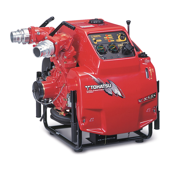
- Page 20 SPECIFICATIONS Model VC85BS Description Portable fire pump Engine Manufacturer TOHATSU CORPORATION Model 2WT78GA Type 2-stroke, water-cooled spark ignition engine Bore ×Stroke 78 mm ×78 mm (3.07 in × 3.07 in) Number of Cylinder Piston displacement 746 ml Authorized output 40.5kW (55PS)
- Page 21 SPECIFICATIONS Model VC85BS Primer Type Rotary-vane vacuum pump (Oil less type) Max. suction height Approx. 9 m (29.5 ft) Pump Type Single suction, single stage, centrifugal pump Number of delivery outlet Discharge port coupling BSP thread 2-1/2” (male) JIS fire thread (B-9912) 2-1/2” (male) (Twin outlet)...
- Page 22 SPECIFICATIONS Performance Curve VC52AS...
- Page 23 SPECIFICATIONS Performance Curve VC72AS...
- Page 24 SPECIFICATIONS Performance Curve VC82ASE...
- Page 25 SPECIFICATIONS Performance Curve VC85BS...
-
Page 26: Operating Device
OPERATING DEVICE VC52AS, VC72AS Discharge valve (Ball cock type) Discharge valve handle Fuel tank cap Discharge valve Engine oil tank cap Discharge port Suction port Engine oil tank Front cowl Suction hose coupling (cap) Pump casing drain cock Battery Knob(wing screw) - Page 27 OPERATING DEVICE VC82ASE Discharge valve handle Fuel tank cap Discharge valve Engine oil tank cap Discharge port Suction port Engine oil tank Suction hose Front cowl coupling cap Pump casing drain cock Knob(wing screw) Battery Priming lever Primer strainer Rear cowl Fuel cock Manual starter handle Priming outlet...
- Page 28 OPERATING DEVICE VC85BS Discharge valve handle Fuel tank cap Discharge valve Engine oil tank cap Discharge port Suction port Engine oil tank Suction hose Front cowl coupling cap Pump casing drain cock Knob(wing screw) Battery Priming lever Primer strainer Rear cowl Fuel cock Manual starter handle Carrying handles...
- Page 29 OPERATING DEVICE Control panel: VC52AS, VC72AS, VC82ASE, Operation panel warning lamps...
- Page 30 OPERATING DEVICE Control panel: VC85BS Pressure gauge for discharge Floodlight projector and battery charging socket Operation panel warning lamps...
-
Page 31: Labels
LABELS WARNING & CAUTION ※For VC52AS and VC72AS... -
Page 32: Operating Precautions
OPERATING PRECAUTIONS Installing pump The fire pump must be installed on level ground. Otherwise, an accident may occur. If the fire pump should be installed on uneven ground, it must be secured. Place the pump as near as possible to water source, and water suction height as low as possible. - Page 33 OPERATING PRECAUTIONS When installing the portable pump in the vehicle, place the vehicle on a level place, and install the pump. When installing the portable pump in the vehicle, make sure to apply the brakes of the vehicle in order to stop the wheels. A serious accident may occur if the vehicle moves.
- Page 34 DESCRIPTION OF DEVICES Carrying handle The fire pump is equipped with four carrying handles. The handles can be manually folded, and opened by rotating them by 90 degrees. Personal injuries may occur when opening or closing the handle. Do not put your hands or fingers into the retractable part when operating the handle.
- Page 35 DESCRIPTION OF DEVICES Rear cowl VC52AS, VC72AS: ・ When you remove the rear cowl, detach the two plug caps from the spark plugs. ・Pull open the cowl at around the support pin. ・Remove the plug caps through the holes in the cowl.
- Page 36 DESCRIPTION OF DEVICES Suction port The diameter of the thread for the fire pump is BSP thread 4” (male), 4-1/2” (male) JIS fire thread (B-9912), 3” (male), 3-1/2” (male) When the pump is running, do not put your finger Into the suction port, you may be seriously injured by the rotating inducer.
-
Page 37: Description Of Devices
DESCRIPTION OF DEVICES Discharge port The diameter of the thread for the fire pump is BSP thread 2-1/2” (male) JIS fire thread (B-9912) 2-1/2” (male) VC82ASE VC52AS, VC72AS VC85BS Screw down discharge Ball valve discharge Screw down discharge Ball valve discharge... - Page 38 DESCRIPTION OF DEVICES Drain valve Use the drain valves to drain water. Drain valves; - at the pump case - at the muffler - at the ball cock discharge valves (Only for ball cock discharge valve type) Close all the valves when operating the fire pump.
- Page 39 The control panel is equipped with all the necessary operating and control instruments as follows. Operation panel The operation panel is equipped with ・Main switch ・All warning lamps, and For VC52AS, VC72AS ,VC82ASE, ・Hour meter ・Over-heat switch For VC85BS ・Automatic suction switch...
- Page 40 If there some problems in the pump, the monitor lamps light on when you turn the start switch on. The warning lamps and the buzzer indicate the following information: VC52AS, VC72AS, VC82ASE Warning lamp : Fuel, Engine oil, Overheat, Suction failure(Only for VC85BS)
- Page 41 In the case of the overheat sensor switch is set in “ON” position, the engine stops automatically when an overheated is detected. Overheat switch ( For VC52AS, VC72AS ,VC82ASE The overheat sensor switch should be always set in “ON” position to avoid a malfunction or destruction of the engine by overheat.
- Page 42 DESCRIPTION OF DEVICES Hour meter (For VC52AS, VC72AS ,VC82ASE) The hour meter indicates the accumulated operation time of the fire pump. Use it to check the running time and maintenance. The meter continues counting as long as main switch is “ON”...
- Page 43 DESCRIPTION OF DEVICES Fuse box Securit y f uses are installed f or electrical circuit in the fuse boxes. There are two fuse boxes: -Black color fuse box is for 15A fuse. -Yellow color fuse box is for 5A fuse. Manual starter If the engine will not start with the starter motor, use the manual starter.
- Page 44 Mechanical governor A built-in mechanical governor controls the throttle valve so that the maximum engine speed does not exceed the revolution shown below. ・VC52AS:5650 r/min ・VC72AS:5720 r/min ・VC82ASE:5500 r/min ・VC85BS:5500 r/min...
- Page 45 DESCRIPTION OF DEVICES Floodlight (Search light) *Option Use the floodlight projector to illuminate the location where this fire pump is operated. Connect the floodlight plug to the pump side outlet socket. Fix the projector to the tripod with tightening the adjust screw. Secure adequate lighting for the location where this fire pump Is operated, otherwise an accident may occur.
-
Page 46: Preparation For Operation
PREPARATION FOR OPERATION Initial charge of battery The battery can be used immediately after filling cells with electrolyte. Do not open the battery after filling it with electrolyte. Because this is maintenance free of electrode.(Sealed type battery) Refer to the INSTRUCTIONS on the battery. Fuel Fill the tank with gasoline until the maximum level by the gauge indication (in red). - Page 47 PREPARATION FOR OPERATION ・Do not breathe in vapor! ・Petrol fumes are very toxic. ・After stopping the engine, do not touch it while it is hot. ・Refill fuel after the engine has cooled down. ・Fuel tank cap should be always tightly closed.
- Page 48 PREPARATION FOR OPERATION Engine oil Refill the 2-stroke engine oil to the oil tank. * Fill the oil tank with the engine oil until “F” level. If the engine oil is not enough filled. The warning buzzer sounds, ( switch “ON”) We recommend that you use engine oil of ISO FB grade or higher.
- Page 49 PREPARATION FOR OPERATION Drain valves Make sure the all drain valves are closed. Discharge valve Make sure the discharge valve is closed. In the case of ball cock discharge valve type, also close the drain cock. __________ Screw down discharge valve ____________ Ball cock discharge valve Closed Circulating Water Cooling System...
- Page 50 PREPARATION FOR OPERATION Overheat protection sensor When you turn on the overheat sensor switch, this device shuts down the engine automatically when the engine has excessively overheated caused by lack of cooling water. Usually turn on the overheat sensor switch. Overheat warning lamp If the temper ature of the cooling water reaches...
-
Page 51: Use Of Operation Panel
USE OF OPERATION PANEL When the warning lamps are off, there is no trouble on each function. * Countermeasures (Warning lamps turn ON) It is necessary to take a countermeasure if the lamp lights up when turning the main switch to the “ON” position. Then take a countermeasure referring to the content “TROUBLESHOOTING”. - Page 52 USE OF OPERATION PANEL Remedy A:Supply fuel. B:Supply 2 stroke engine oil. C:Read the TROUBLE SHOOTING and remedy it. In the case of overheat ・Check the cause and remedy it. ・Turn off the overheat sensor switch and start the engine. After confirming the lamp is off, return the switch to the "ON"...
- Page 53 USE OF OPERATION PANEL Before removing the electrical equipment, turn the main switch off and remove the battery. When removing the battery cable from the battery terminal, always disconnect the negative(-) cable first. When connecting battery cable, connect the positive(+) lead first. If you connect the negative(-) lead first, hydrogen gas generated by the battery may cause an explosion.
- Page 54 USE OF OPERATION PANEL Hour meter (For VC52AS, VC72AS, VC82ASE) (1) The hour meter starts counting when the main switch is turned “ON” position. (2) The hour meter only works during the main switch is “ON” position. (3) There is no reset capability.
- Page 55 ENGINE START Installation pump Since the temperature around the engine become high because of the muffler and exhaust gas, install the pump on level ground at least three meters away from inflammable materials including dry grass and wood. Exhaust gas, which contains carbon monoxide, is a deadly poisonous gas with no color and smell.
- Page 56 ENGINE START Starting engine Wear proper hearing protection during operation. While engine is running, do not touch the high voltage Ignition wire attached to spark plug. This wire carries very high voltage which will cause injury and bodily harm. Do not operate pump on dry grass. The exhaust system gets very hot and will ignite dry grass.
- Page 57 ENGINE START 2. Turn the throttle dial to the “START SUCTION” position. START SUCTION 3. Turn the main switch to the “START” position. Release the main switch immediately after the engine starts. 1. Extended operation of the starter motor will run the battery drain. Operate the starter motor for maximum 3 seconds.
- Page 58 ENGINE START Starting engine by the manual operation (Using a recoil starter) If electric starter does not work, use the manual starter. When you use the manual starter, operate the engine as shown below. 1. Turn the fuel valve to open position, this will allow fuel to flow to the carburetor.
-
Page 59: Engine Start
ENGINE START When you start the engine using the manual starter, engage the starter ratchet by pulling the starter rope slowly toward you. Pull the starter rope fast at once (in a breath) *Holding the fire pump in place with your foot. Dry operation This portable pump has an outside water cooling system, limit the duration of dry operation so that it is within the following time periods. - Page 60 PRIME AND DISCHARGE While the engine is running, do not touch the rotating parts of the pulley or belt. This can cause personal injuries. If the pump cannot suck water during the operation of the vacuum pump for 30 seconds, or cannot keep the water in the water path of the pump during the water discharge operation, check the following: ・Is the tip of the suction pump hose completely under the water...
- Page 61 PRIME AND DISCHARGE Limit the vacuum pump operating time within 30 seconds. If the pump cannot suction water within 30 seconds, it may have an another problem. Refer to the contents “16 TROUBLESHOOTING” to rectify the problem. When priming water from a water source that is considerably lower than the pump, suction may fail to bring water up to pump.
- Page 62 PRIME AND DISCHARGE Before opening water discharge port or valve of the pump, be sure to warn the person holding the nozzle or the branch pipe to check the nozzle is opened and ready to discharge water During operation, check the suction and discharge hoses They must be free of kinks, pinches, etc., possibly caused from emergency vehicles rolling over hose.
- Page 63 PRIME AND DISCHARGE Performing relayed water supply (When using water from fire hydrant) 1. Determine the pump pressure in consideration of the water discharge pressure (nozzle pressure), hose pressure loss, and height loss. Pump pressure = needed pressure + height loss + friction loss 2.
- Page 64 PRIME AND DISCHARGE Be sure not to close the discharge valves of all the pumps and the nozzle until all the pumps stopped and the fire hydrant on-off valve is closed. 8. Set the discharge valve to the half-open position, and open all the drain valves to drain the remaining water as maintenance after operation.
- Page 65 PRIME AND DISCHARGE Relay pumping operations In the case of relay pumping operations training in a flat place, if the number of extending hose is less than ten, use the safety nozzle attached. Description of relay pumping operation...
-
Page 66: Prime And Discharge
PRIME AND DISCHARGE Preparation for operation Do not close the discharge valve of source pump , relay pumps and fire nozzle. If the discharge valves or nozzle are(is) closed, there will be a risk of damage to the pumps and hoses with excessive pressure or water hammer. - Page 67 PRIME AND DISCHARGE Start the Relay pump 1. Make sure that the discharge valve is opened and wait for supplied water. 2. Check that the water was supplied from the source pump. At first, the hose swells due to air pressure. Step on a hose to judge whether the swelling of the hose is due to water or air.
-
Page 68: Engine Stop
ENGINE STOP 1. Return the throttle dial to “LOW” position. 2. Close the discharge valve. ____________ Screw down discharge valve Turn the discharge valve handle to the left (Clockwise). ____________ Ball cock discharge valve Turn the discharge valve handle to close The discharge port can be turned approximately 90 degrees. -
Page 69: Maintenance After Operation
MAINTENANCE AFTER OPERATION Drain Water 1. Open the drain valves and drain all the water from the pump. Do not leave water in the pump. 2. Close the drain valves for the next operation. Check Suction Performance. After the drainage of all the water from the pump, 1. - Page 70 MAINTENANCE AFTER OPERATION 4. After a vacuum is produced, return the priming lever to the original position immediately, and stop the engine. 5. Check the vacuum pressure of the pressure gauge for suction is below -0.08MPa(-12 psi). 6. In order to check if there is no vacuum leak, leave it for 30 seconds and confirm that the pointer of the pressure gauge for suction keep the same pressure indicated.
- Page 71 MAINTENANCE AFTER OPERATION Fuel/Oil 1. Fuel ・Fill fuel until the maximum level of the fuel tank. T h e m a x i m u m l e v e l c a n b e c o n f i r m b y t h e Indicator (Red) .
- Page 72 MAINTENANCE AFTER OPERATION 2. Engine oil Fill the oil tank with 2-stroke engine oil up to the “F” level. Engine oil tank capacity : 1.6L (0.42 gal) Use 2-stroke engine oil of ISO FB grade or higher. 3. Governor oil Check the oil level using the dipstick.
- Page 73 MAINTENANCE AFTER OPERATION Cleaning strainer for prime Remove the strainer cap and clean the strainer with fresh water. If the strainer is dirty with dust, etc., vacuum performance efficiency will be reduced. W h e n i n s t a l l i n g t h e s t r a i n e r , exercise care so that the O-ring does not get caught in, and tighten the ring nut securely.
- Page 74 MAINTENANCE AFTER OPERATION Charging battery <Battery> You must read the safety instructions carefully and/or warnings before using or charging the batteries. Hydrogen gases from the battery are explosive. Keep battery away from flame and sparks. Charge the battery in well ventilated area. Do not charge battery in unventilated area.
- Page 75 MAINTENANCE AFTER OPERATION 1. Be sure to charge the battery after each operation. Battery charger plug socket Location <Specification of accessory socket> ・ Voltage : DC12V ・ Max. allowable current : 5A 2. Turn off the main switch. 3. Confirm that there is no dirt, no slack, no backlash of the terminal.
- Page 76 MAINTENANCE IN COLD CONDITION Infuse anti-freezing fluid If the temperature around the pump could be subzero, the inside of the pump can be frozen up. In this case, the pump or the vacuum pump may not be operated. And also the pump unit including engine and muffler, may be damaged or broken.
-
Page 77: Maintenance In Cold Condition
MAINTENANCE IN COLD CONDITION 4. Attach the plastic tube to the pump drain valve and open the valve at the pump case. 5. Insert the plastic tube in the container filled with antifreeze fluid (180ml/0.04gal-200 ml/0.05gal). Turn the throttle dial at“SUCTION・START”position. Turn the main switch at ”ON”... - Page 78 MAINTENANCE IN COLD CONDITION 9. Return the throttle dial to “LOW” position. 10.Turn the main switch off. 11.Close the fuel cock. <For discharge valve> Fill antifreeze fluid into the seal area of the discharge valve. *To use a long nozzle containing is helpful when you pour antifreeze fluid.
- Page 79 MAINTENANCE IN COLD CONDITION <For primer> 1. Remove the strainer and strainer cup. 2. Inject antifreeze (undiluted 50 ml / 0.01gal) into the strainer guide. 3. After injection, assemble the strainer. When assembling or disassembling the strainer assembly, tighten or loosen the ring nut while holding and pushing the strainer cap.
-
Page 80: Use Of Accessories
USE OF ACCESSORIES Battery Battery performance deteriorates if the temperature falls. Further, battery may freeze if the specific gravity is low. Battery specification Capacity: 16 Ah ・Hydrogen gases from the battery are explosive. Keep battery away from flame and sparks. ・Hydrogen gases emitted from the battery will also cause severe burns to skin and damage to clothing. - Page 81 USE OF ACCESSORIES Battery charger Read the instruction manual of the battery charger. The instruction manual is packed with the charger. Set the battery charger on a suitable non-inflammable stand or fix on wall ,not directly onto the ground.
- Page 82 USE OF ACCESSORIES Pumping plate When you use the fire pump without a nozzle as a water lifting pump, such as pumping water out of a cellar, put the pumping plate* with holes in between the discharge port adapter screw and the bracket packing in order to prevent the overheating of the engine and the pump cavitation which may cause damages to the pump.
-
Page 83: Periodical Inspection
PERIODICAL INSPECTION Pay your serious attention to keep the pump in a good condition. 1. To store a fire pump properly: ・ Place it in a level place. ・ Keep it in a dry area. High humidity may cause corrosion in some parts of the pump. - Page 84 PERIODICAL INSPECTION Perform periodical inspections and maintenance according to the following procedures. Inspection intervals Description Inspection items Measure Fuel Impurities (ie. Clean*1 ● Water and/or waste) ● Level Refuel ● Preservation Replace*1 period 6 month or Fuel more System ● Degradation Replace*1 (ie.
- Page 85 PERIODICAL INSPECTION Inspection intervals Description Inspection items Measure ● Starting Battery Voltage measure Charge system (Sealed ● Period of use Replace type) *1 *2 ● V-Belt Wear, crack, belt, Replace*1 tension ● Priming Strainer Clogging or broken Clean or system mesh replace Is not locked...
- Page 86 Therefore, for safety reasons, use only Tohatsu genuine parts. Tohatsu bears no responsibility for any personal injuries or equipment damage that may result from use of parts or accessories obtained from outside sources. Environmental protection measures Dispose of oil, fuel, batteries, etc.
- Page 87 ・Remove the cowl pins from the hooks. ・ De t a ch t he spa rk p lu g ca p a t t wo lo ca t ion s. (For VC52AS, VC72AS) ・Pull and turn the cowl at around the supporting pins.
- Page 88 SERVICE & MAINTENANCE ・Pass the spark plug caps through the holes for the leads. ・Remove the cowl from the pins. (For VC52AS, VC72AS) ・Remove the cowl Remove the front cowl first, and the rear cowl second. Cowl installation Assemble order is in reverse order of the opening.
- Page 89 SERVICE & MAINTENANCE ・Set the cowl with two hooks shown in the picture. The hooks are located in 2 places. The hooks must be aligned to the socket of the grommet before insert firmly. Front ・Set the cowl from upper side as shown in the picture ・The hooks are located in 2 places.
-
Page 90: Service & Maintenance
SERVICE & MAINTENANCE Vacuum pump strainer Maintenance Incorrect installation of the strainer may cause a vacuum leak. Be sure to install the strainer correctly. Refer to the content “MAINTENANCE AFTER OPERATION” Wash the strainer with fresh water after each use. ・On the occasion of washing the strainer, turn the ring nut. - Page 91 Refer to “PREPARATION FOR OPERATION” Vacuum pump V belt V belt. Check the Check the V belt every year or every 100 hours operating time. V belt size: ・VC82ASE:A-29 ・VC85BS :M-32 ・VC52AS,VC72AS:A-29...
- Page 92 SERVICE & MAINTENANCE Spark plug 1. Remove the plug cap, and remove the spark plug. 2. Use a wire brush or spark plug cleaner, clean the electrode of the spark plug. 3. Check the spark plug for excessive carbon deposits, electrode erosion and check the washer for damage.
- Page 93 SERVICE & MAINTENANCE Battery General safety information Follow the safety instructions on the battery. When charging batteries, a highly explosive oxyhydrogen gas mixture is produced. Do not charge a battery in a poorly ventilated place. Do not smoke near the battery. Danger of injury due to caustic substances of battery.
- Page 94 SERVICE & MAINTENANCE Electric equipment Only expert electricians or trained staff members should handle electrical equipment. Be sure to disconnect battery cables before handling electrical equipment. Disconnect the negative terminal first, then disconnect the positive terminal. When connecting battery cables, connect the positive terminal first, then connect the negative terminal.
- Page 95 SERVICE & MAINTENANCE Suction performance check Limit continuous operating time of the vacuum pump to 30 seconds or less. Operating the pump for 30 seconds or more continuously may cause the engine to overheat. If the engine overheats, wait until it cools down.
- Page 96 SERVICE & MAINTENANCE Water leak check 1. Connect one end of the suction hose to the suction port. Place the other end of the hose into the water more than 300mm (11.8 in) from the surface, and then close the discharge valve handle. 2.
-
Page 97: Troubleshooting
TROUBLESHOOTING Typical causes of engine troubles are listed in the following table. Trouble Action Cause ● ● ● Low fuel Refuel Replace with ● ● ● ● ● Deterioration of fuel new fuel. Clean the ● ● ● ● ● Fuel filter clogging clogging Fuel pipe kink... - Page 98 TROUBLESHOOTING Trouble Cause Action ● Low fuel Refuel. ● Deterioration of fuel Replace with new fuel. ● Fuel filter clogging Clean the clogging. Fuel pipe kink ● Fix routing of pipe. or snap Clean or replace with ● Carburetor new Carburetor. Throttle dial at other Set dial to “Start”...
- Page 99 TROUBLESHOOTING Trouble Action Cause Plug in surely. Spark plug cap ● ● ● ● comes off Replace with Use of unspecified ● ● ● ● ● ● specified spark spark plug plug. Spark plug fouling Clean or replace ● ● ● ●...
- Page 100 TROUBLESHOOTING Trouble Cause Action Plug in surely. Spark plug cap ● comes off Use of unspecified Replace with specified ● spark plug spark plug. Spark plug fouling Clean or replace with ● (No spark or weak specified spark plug. spark) Battery loose Clean terminal and/or ●...
- Page 101 TROUBLESHOOTING Trouble Action Cause Replace with spare fuse. When the blowout of the fuse happens repeatedly, check a cause. 15A: Battery cable ● 5A fuse blown reverse connection, operation panel components and search light connector. 5A: Charging connector. Check terminals, Starter motor cords and screws.
- Page 102 TROUBLESHOOTING Trouble Action Cause Replace with spare fuse. When the blowout of the fuse happens repeatedly, check a cause. 5A fuse blown 15A: Battery cable reverse connection, operation panel components and search light connector. 5A: Charging connector. Check terminals, cords Starter motor and screws.
- Page 103 TROUBLESHOOTING Trouble Action Cause Piston, piston ring ● ● ● ● ● Correct or replace. or cylinder excessively worn Carbon deposition in the ● ● ● Clean out. combustion chamber Suction height too Make it pump high or length too location to nearer long and/or lower...
- Page 104 TROUBLESHOOTING Trouble Action Cause Piston, piston ring ● or cylinder Correct or replace. excessively worn Carbon deposition ● in the combustion Clean out. chamber Suction height too Make it pump location high or length too ● to nearer and/or lower long position.
- Page 105 TROUBLESHOOTING Trouble Action Cause Tighten securely a Vacuum pipe clump of vacuum loose or cracking pipe or replace. Strainer cap loose Tighten securely or or “O” ring failure replace. V belt damaged Replace. or worn Vacuum pump Repair or replace. rotor shaft seizing Vane, Side plate Replace.
- Page 106 TROUBLESHOOTING Trouble Cause Action Tighten securely a Vacuum pipe loose ● ● clump of vacuum pipe or or cracking replace. Strainer cap loose Tighten securely or ● ● or “O” ring failure replace. V belt damaged or ● ● Replace. worn Vacuum pump rotor ●...
- Page 107 TROUBLESHOOTING Trouble Action Cause Drain valve(s) are Close securely. not closed Suction port strainer clogged Clean out. with dead leaf or waste etc. Discharge valve ● Open securely. imperfect open Gauge pipe Tighten securely. connector loose Replace a gasket if or gasket necessary.
- Page 108 TROUBLESHOOTING Trouble Action Cause Drain valve(s) are ● ● ● Close securely. not closed Suction port strainer ● ● clogged with dead Clean out. leaf or waste etc. Discharge valve ● Open securely. imperfect open Gauge pipe Tighten securely. ● ● ●...
- Page 109 TROUBLESHOOTING Trouble Action Cause Change the nozzle Discharge nozzle for suitable size or ● ● too large incorporate safety nozzle. Spray nozzle Clean out. clogged Governor ● ● adjustment out of Readjust it securely. specified range Governor link ● ● ● ● ● Attach it securely.
- Page 110 TROUBLESHOOTING Trouble Action Cause Change the nozzle for Discharge nozzle suitable size or ● too large incorporate safety nozzle. Spray nozzle ● Clean out. clogged Governor ● adjustment out of Readjust it securely. specified range Governor link ● ● ● Attach it securely.
-
Page 111: Appendix
APPENDIX Tightening torque specifications. M5 M6 M8 M10 N・m Standard Bolt lb・ft 0.07 0.16 0.4 0.6 1.3 kgf・m N・m lb・ft Heat Treated Bolt 0.9 2.4 kgf・m... -
Page 112: Tools And Standard Accessories
TOOLS AND STANDARD ACCESSORIES Description Parts No. Remarks Quantity Owner’s manual 003-12054-1 Tool kit bag 151-39010-2 Tools (Crown spanner 21mm) General tool Tools (Handle for spanner) General tool Spark plug 9701-1-1014 BPR7HS-10 Pilot bulb 1K1-34321-0 12V-3.8W Pumping plate 151-39045-0 Battery charger 159-39039-4 3T5-76246-0 Fuse... -
Page 113: Wiring Diagram
WIRING DIAGRAM WIRING DIAGRAM: VC82ASE... - Page 114 WIRING DIAGRAM WIRING DIAGRAM : VC85BS...
- Page 115 WIRING DIAGRAM WIRING DIAGRAM : VC52AS, VC72AS...
- Page 116 TOHATSU CORPORATION Address: 3-5-4 Azusawa, Itabashi-ku, Tokyo, JAPAN FAX: +81-3-3966-2951 Phone: +81-3-3966-3137 003-12054-1 1612(タ)300...
Need help?
Do you have a question about the VC52AS and is the answer not in the manual?
Questions and answers