Table of Contents
Advertisement
Advertisement
Table of Contents

Related Manuals for Aqua Lung APEKS TX 50


Summary of Contents for Aqua Lung APEKS TX 50
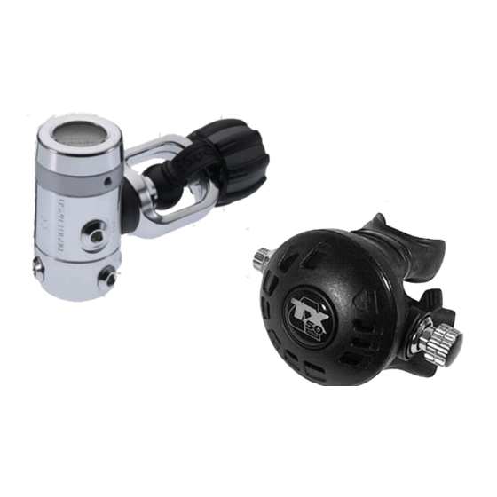
- Page 1 APEKS TX 50 Regulator TECHNICAL MANUAL REV 05/13...
- Page 2 Aqua Lung International. It may not be distributed through the internet or computer bulletin board systems without prior consent in writing from Aqua Lung International.
-
Page 3: Change Record
CHANGE RECORD Change No. Date Title or description Change made by... -
Page 4: Table Of Contents
TX50 Technical Manual CONTENTS CHANGE RECORD ..................3 INTRODUCTION ..................5 FIRST STAGE DISASSEMBLY PROCEDURES ......... 6 FIRST STAGE REASSEMBLY PROCEDURES .......... 8 ADJUSTING THE FIRST STAGE ...............11 FIRST STAGE FINAL ASSEMBLY ............12 SECOND STAGE DISASSEMBLY PROCEDURES ........13 SECOND STAGE REASSEMBLY PROCEDURES ........ -
Page 5: Introduction
Aqua Lung Service & Repair Seminar. If you do not completely under- 2. All service and repair should be carried out in a work area stand all of the procedures outlined in this manual, contact Aqua Lung to specifically set up and equipped for the task. Adequate lighting, speak directly with a Technical Advisor before proceeding any further. -
Page 6: First Stage Disassembly Procedures
TX50 Technical Manual DISASSEMBLY PROCEDURES Secure the vise mounting tool and first stage into a bench vise adapter (PN NOTE: Before performing any disassembly, refer to the exploded 100398) or vise. parts drawing, which references all mandatory replacement parts. These parts should be replaced with new, and must not be reused under any circumstances –... - Page 7 Using the o-ring removal tool (PN 944022), remove the NOTE: You may encounter a new revision spring carrier. This o-ring (13) from the outside and o-ring (17) from the inside was an inline change made as a cost savings. Either version of of the turret retaining bolt (15).
-
Page 8: First Stage Reassembly Procedures
TX50 Technical Manual Before starting reassembly, perform parts Remove the conical filter (36) and o-ring (10) from the yoke clamp connector (32). Use a 6mm hex key to remove the filter cleaning and lubrication in accordance with guard (31) from the clamp connector. Discard filter, guard and o-ring. Procedure A: Cleaning and Lubricating on page (27). - Page 9 Use a 6mm hex key, tighten down the spring adjuster (22) Install the small o-ring (17) into the turret bolt (15). Place the until 1-2 threads (¼” from top) are exposed. larger o-ring (13) at the base of the threads. Turn the first stage over, hold the HP valve (11) by the stem Install the turret bolt (15) through the turret (8).
- Page 10 TX50 Technical Manual Place an unlubricated o-ring Add o-ring (29) to the dust cap. Attach the dust cap (28) to the (10) into the yoke clamp yoke clamp (27) by stretching it over the flange at the top of connector (32). Then place the the yoke clamp.
-
Page 11: Adjusting The First Stage
Thread the DIN connector Attach the first stage to a upwards into the first stage calibrated test bench or a body until snug. cylinder filled to 3000 psi (206 bar). Open the bleed valve on the MP gauge. CAUTION: The DIN connector must be held vertically CAUTION: Before pressurizing your first stage, check that while being installed upwards into the body until snug. -
Page 12: First Stage Final Assembly
TX50 Technical Manual Let the first stage stand With the end cap in place, pressurized for several recheck the MP to confirm minutes. Check that the MP, there has been no change. remains stable. If the MP rises more than 5 psi (0.3 bar), it indicates a leak. -
Page 13: Second Stage Disassembly Procedures
DISASSEMBLY PROCEDURES Remove the diaphragm cover (8) and diaphragm (9) from the case (10). Use an 11/16 inch open end wrench to remove the heat exchanger (2) from the case. TX 50 Second Stage Disassembly Using two 11/16 inch open end wrenches, hold the heat exchanger (2) stationary and turn the hose swivel nut... - Page 14 TX50 Technical Manual Unthread the adjusting screw (23) from the valve spindle (20). Use Insert the seat adjustment tool (PN AT51) into the threaded your fingernail to remove the plug (22) from the adjusting screw. end of the valve spindle (20) and turn the seat (18) out 6-7 turns counter-clockwise.
-
Page 15: Second Stage Reassembly Procedures
REASSEMBLY Inspect the exhaust valve (11) for damage. If the exhaust valve (11) was removed, replace by pushing the tail through the retaining hole on the outside of the case (10) until the barb engages on the inside. Align the rib so it is horizontal. - Page 16 TX50 Technical Manual Install the o-ring (3) onto If the lever (21) was removed, install the lever in correct orientation. With air outlet hole facing you and threaded end the valve spindle (20). to the right, lever should be pointing to the left. Install the o-ring (27) onto the stem of the shuttle valve (28).
- Page 17 Continue to screw the adjusting knob (23) clockwise into Slide the o-ring (3) the valve spindle (20) until the holes for the spring pin down the threaded (17) are clear. Install the spring pin. Be sure that it sits evenly in end of the valve spindle (20).
- Page 18 TX50 Technical Manual While holding the rim of the case (10) at eye level, use Replace the plug (22) the seat adjustment tool (PN AT51) to turn the seat (18) into the adjustment clockwise until the lever drops about ⅛” below the case rim. Then, knob (23).
-
Page 19: Final Testing
FINAL TESTING FINAL ADJUSTMENT PROCEDURES WARNING: Compressed air can be highly explosive and External Leak Test is dangerous if misused. Ensure cylinder valve is opened slowly. Use Eye and Ear Personal Protective Equipment when performing any tests involving compressed air . Using an in-lb torque wrench with a 9/16”... -
Page 20: Final Assembly
TX50 Technical Manual FINAL TESTING PROCEDURES Place the end of the TX Lever Height Tool onto the purge button (5) with the “GAS FLOW” up. Depress the purge but- ton by pushing the tool towards the second stage until it stops against the front cover. - Page 21 Table 1: First Stage Troubleshooting Guide SYMPTOM POSSIBLE CAUSE TREATMENT 1. HP valve (11) worn or damaged. 1. Replace HP valve. 2. HP valve seat worn or damaged. 2. Replace body (5). High Pressure Creep 3. Turret bolt (15) internal wall dam- 3.
- Page 22 TX50 Technical Manual Table 2: Second Stage Troubleshooting Guide SYMPTOM POSSIBLE CAUSE TREATMENT 1. Excessively high first-stage 1. Refer to Table 1 - First Stage intermediate pressure. Troubleshooting Guide. 2. MP Seat (29) damaged or worn. 2. Replace Rubber Seating. 3.
- Page 23 Table 3: List of Tools and Service Kits PART # DESCRIPTION APPLICATION 111610 MP Test Gauge Medium pressure testing 108362 MP Gauge Softcase Protective Case for MP Test Gauge Brass O-ring 944022 Tool Kit or Removal and installation of o-rings Plastic O-ring 103102 Tool...
- Page 24 TX50 Technical Manual Table 3: List of Tools and Service Kits PART # DESCRIPTION APPLICATION In-line Adjustment 100190 Final adjustment and tuning Tool TX Cover AT31 Assembly/disassembly of case cover (7) Tool AT69 Lever Height Tool Lever Height Measurement 9-45171 Side Cutters Cut clamp (13), trim exhaust valve (11) Magnifier with...
- Page 25 Table 4: Torque Specifications First Stage PART # DESCRIPTION / KEY ITEM # TORQUE AP1407 Yoke Connector (32) 14.7 ft-lbs (20 Nm) DIN Handwheel Connector (34) AP1471 Turret Retaining Bolt (15) 70 in-lbs (8 Nm) AP1486 AP0203 MP Hose AP1408 40 in-lbs (4.5 Nm) AP1487 Blanking Plugs (9, 18, 19)
- Page 26 TX50 Technical Manual Table 6: Recommended Cleaners and Lubricants LUBRICANT/CLEANER APPLICATION SOURCE Aqua Lung, PN 820466, or Lubrication Technologies Christo-Lube MCG 111 All o-rings 310 Morton Street Jackson, OH 45640 (800) 477-8704 CAUTION: Silicone rubber requires no lubrication or preservative treatment.
-
Page 27: Procedure A: Cleaning And Lubricating
When it comes to issues of nitrox safety and compatibility, the concerns lie primarily with the first stage as it is subjected to high inlet pressures. High inlet pressures lead to adiabatic compression or heating of the gas. The Aqua Lung or Apeks regulator product described in this manual, when properly cleaned and assembled, is authorized for use with enriched air nitrox (EAN) that does not exceed 40% (EAN 40). -
Page 28: First Stage Schematic
TX50 Technical Manual TX 50 First Stage 2001-Present (Military Only) (DST Style) 14.7 ft/lbs 20 Nm 40 in/lbs 4.5 Nm 70 in/lbs 8 Nm 17 13 40 in/lbs 4.5 Nm 40 in/lbs 4.5 Nm Key # Part # Description Key # Part # Description 17 ---- AP1299P O-ring (10 pk) -
Page 29: Second Stage Schematic
TX50 Second Stage 26.5 in-lbs 3 Nm Key # Part # Description Key # Part # Description ------ AP0510SQ TX50, Second Stage w/ 1/2" Hose 21 ---- AP2035 Lever ------ AP0503 TX50 Octopus 22 ---- AP2030 Plug ------ AP0219/AA Universal Second Stage Repair Kit 23 ---- AP2029 Adjusting Screw, TX50 24 ---- AP1409P... -
Page 30: Maintenance Notes
TX50 Technical Manual Maintenance Notes... - Page 31 Maintenance Notes...
- Page 32 APEKS TX50 REGULATOR TECHNICAL MANUAL 2340 Cousteau Court • Vista, CA 92081 Phone (760) 597-5000 • Fax (760) 597-4900 www.aqualung.com/militaryandprofessional Literature PN 100580 REV 05/13 ©2013 Aqua Lung International...
Need help?
Do you have a question about the APEKS TX 50 and is the answer not in the manual?
Questions and answers