Table of Contents
Advertisement
Quick Links
Advertisement
Table of Contents

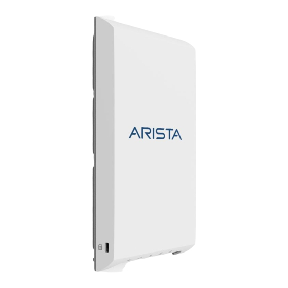
Summary of Contents for Arista W-118
- Page 1 Quick Start Guide W-118 Access Point Arista Networks www.arista.com DOC-03485-01...
- Page 2 Inc. The information contained herein is subject to change without notice. Arista Networks and the Arista logo are trademarks of Arista Networks, Inc in the United States and other countries. Other product or service names may be trademarks or service marks of...
-
Page 3: Table Of Contents
Bottom Panel of W-118.........................9 Chapter 4. Install the W-118......................11 Mount the W-118.........................11 Power On the W-118........................14 Using the W-118 with Power Adapter................15 Connect the W-118 to the Network..................15 Connect the W-118 using PoE.................... 16 Chapter 5. W-118 Troubleshooting....................17... -
Page 4: Chapter 1. About This Guide
Installing the AP constitutes your acceptance of the terms and conditions of the EULA mentioned above in this document. Intended Audience This guide can be referred by anyone who wants to install and configure the W-118 access point. Document Overview This guide contains the following chapters: •... -
Page 5: Chapter 2. Package Content
Note down the MAC address, before mounting the device on the ceiling or at a location that is difficult to access. If the package is not complete, please contact the Arista Networks Technical Support Team at support-wifi@arista.com, or return the package to the vendor or dealer where you purchased the... -
Page 6: Chapter 3. W-118 Overview
Right Panel of the W-118. (page 5) • Rear Panel of the W-118. (page 7) • Bottom Panel of the W-118. (page 9) Right Panel of W-118 The right panel of the W-118 has 6 LEDs that indicate the functioning state of the device. - Page 7 | 3 - W-118 Overview | 6 Figure: W-118 Right Panel The following table indicates the device states based on the LEDs. Table 1. W-118 LED Status Description Status Description Power Solid Green Power ON Power OFF Uplink Solid Green...
-
Page 8: Rear Panel Of W-118
Rear Panel of W-118 The rear panel of the W-118 has an Ethernet port labeled WAN, that enables you to connect the device to a wired LAN through a switch or a hub and provides the power for the device by using the... - Page 9 | 3 - W-118 Overview | 8 Figure: W-118 Rear Panel Table 2. W-118 Rear Panel Port Description Connector Type Speed/Protocol PASSTHROUGH This is a wired port that RJ45 facilitates extension of the wired network after the AP is mounted on the wall.
-
Page 10: Bottom Panel Of W-118
This port also provides the power for the device using the 802.3af standard Bottom Panel of W-118 The bottom panel of W-118 and its corresponding ports are described below. Figure: W-118 Bottom Panel Port Description Connector Type Speed/Protocol... - Page 11 | 3 - W-118 Overview | 10 Ethernet (LAN2) Gigabit Ethernet port that RJ45 10/100/1000 Mbps Gigabit can be used for wired Ethernet extension for an SSID. Ethernet (LAN1) Gigabit Ethernet port that RJ45 10/100/1000 Mbps Gigabit can be used for wired Ethernet extension for an SSID.
-
Page 12: Chapter 4. Install The W-118
Take a configured W-118, that is, ensure that a static IP is assigned to the device or the settings have been changed for DHCP. Note down the MAC address and the IP address of the device in a safe place before it is installed in a hard-to-reach location. - Page 13 | 4 - Install the W-118 | 12 2. Affix the mounting bracket on to the wall using the appropriate screws from the mounting accessories included in the package. 3. Connect the cables to the appropriate ports in the rear-side of the device.
- Page 14 | 4 - Install the W-118 | 13 4. Mount the device on the bracket by aligning the two notches on the bracket with the two grooves on the rear panel of the device. Slide the device and tighten it onto the bracket with the...
-
Page 15: Power On The W-118
For example, use serial numbers, so that you can easily identify the devices. Power On the W-118 The W-118 device can be powered on by plugging one end of the Ethernet cable into the PoE (802.3af) switch or injector and the other end into the Ethernet/PoE port on the W-118. Ensure the... -
Page 16: Using The W-118 With Power Adapter
5. Log on to the server using ssh and run the get sensor list command. You will see a list of all Arista devices that are recognized by the server. Single Sign-On users can go to the Devices tab in Wireless Manager and check whether the device is visible under the Devices tab. -
Page 17: Connect The W-118 Using Poe
| 4 - Install the W-118 | 16 Connect the W-118 using PoE If you are using a PoE injector, make sure the data connection is plugged into a suitable switch port with proper network connectivity. -
Page 18: Chapter 5. W-118 Troubleshooting
Chapter 5. W-118 Troubleshooting The table below lists some of the troubleshooting guidelines for W-118. Diagnosis Solution The device did not receive a valid IP address via the Ensure that the DHCP server is On and available on the DHCP. -
Page 19: Chapter 6. Appendix A: Ap-Server Mutual Authentication
Chapter 6. Appendix A: AP-Server Mutual Authentication The AP-server communication begins with a mutual authentication step in which the AP and server authenticate each other using a shared secret. The AP-server communication takes place only if this authentication succeeds. After the authentication succeeds, a session key is generated. All communication between the AP and server from this point on is encrypted using the session key.


Need help?
Do you have a question about the W-118 and is the answer not in the manual?
Questions and answers