
Related Manuals for ReSound TrimFlex Plus BTE


Summary of Contents for ReSound TrimFlex Plus BTE
- Page 1 Technical Manual ReSound TrimFlex Plus BTE TFP70-V BTE Global Technical Operations gto.gnresound.com Lautrupbjerg 9 • DK-2750 Ballerup • Denmark E-Mail: Service@gnresound.dk...
-
Page 2: Table Of Contents
Doc 0121830 rev. B Table of contents Description...........................3 Part list..........................4 Dis-assembly HI ........................5 Microphone & Receiver ....................6-7 Mounting PB Battery Springs & Telecoil ................8 Test & Trimmer Reference ....................9 Page 2 of 9... -
Page 3: Description
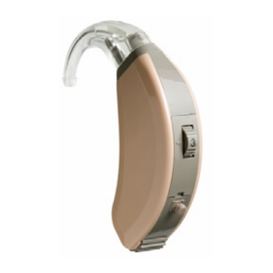
Doc 0121830 rev. B ReSound is introducing the latest in our trimmer family, the TrimFlex+ BTE with its improved features. The TrimFlex+ BTE is 100% digital but can be adjusted in an easy, fast and flexible way by using the trimmers - no computer or fitting software is needed. -
Page 4: Part List
Part List Doc 0121830 rev. B Item Part No Item Part No AMP (COMPL IN FRAME) 16015000 REC COMPL MOUNT W/WIRES,SUSP 613-004-001-33 T-COIL-HOLDER INTEGRA 513-010-100-01 REC SUSPENSION INTEGRA 550-003-000-00 T-COIL Y21 INTEGRA,S-VDD/ NANO 576-002-080-00 WIRE,ESW,RED,7X32U,23MM 15129623 PB SWITCH 611-000-010-00 WIRE,ESW,AMBER7X32U,23MM 15129723 BATT. -
Page 5: Dis-Assembly Hi
Dis-assembly HI Doc 0121830 rev. B Front cap Slot Insert a screwdriver in the Pull out the ear hook Gently remove the front cap slot to release the front cap Gently separate the housing parts from frame as shown. Tip: Open the batt. -
Page 6: Microphone & Receiver
Microphone & Receiver Doc 0121830 rev. B The mic is covered in the The rec is covered with a The rec is covered indicated area by standard nail second layer to protect the with standard nail varnish to protect the mic and soldering pads and to keep the varnish to protect the to keep the wires in place... -
Page 7: Microphone & Receiver
Microphone & Receiver Doc 0121830 rev. B Pull back till suspensions Gabs flush with dotted line Connect and place the rec wires as shown Add grease/Molycote onto the edge of both sides of the receiver Add grease/Molycote on both housing parts compartment Page 7 of 9... -
Page 8: Mounting Pb Battery Springs & Telecoil
Replacing PB Battery Springs & Telecoil Doc 0121830 rev. B Amplifier is shown from both sides Batt spring (+) Batt spring (-) Unsolder the battery Soldering points for the two PB terminals springs from the PCB To release the contacts from the BTE frame, push the encircled area and lift out the spring/... -
Page 9: Test & Trimmer Reference
Test & Trimmer Reference Doc 0121830 rev. B 2cc coupler Attach the HI to the 2cc coupler and insert the Screwdriver, trimmers battery pill size 13 into the batt. door. Place p/n 8090-369 the HI in the test chamber as shown. No frame or test fixture are required Page 9 of 9...