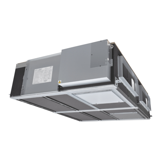
Mitsubishi Electric Lossnay LGH-150RVXT-E Installation Instructions Manual
Energy recovery ventilator
Hide thumbs
Also See for Lossnay LGH-150RVXT-E:
- Operating instructions manual (11 pages) ,
- Handbook (84 pages) ,
- Operating instructions manual (15 pages)

Related Manuals for Mitsubishi Electric Lossnay LGH-150RVXT-E


Summary of Contents for Mitsubishi Electric Lossnay LGH-150RVXT-E
- Page 1 1509876HC8401 Lossnay Models: LGH-150RVXT-E LGH-200RVXT-E LGH-250RVXT-E Installation Instructions...
-
Page 2: Table Of Contents
Lossnay Energy Recovery Ventilator MODELS: LGH-150RVXT-E LGH-200RVXT-E LGH-250RVXT-E Installation Instructions (For use by dealer/contractor) Contents Safety precautions ..........1 Outline drawings ..........3 Before installation ..........3 Standard installation examples......4 Installation method ..........4 Function settings ..........13 Check points after installation work ....22 Trial operation ............22 This product needs to be installed properly in order to ensure maximum functionality as well as safety. - Page 3 Safety precautions (continued) CAUTION Do not place a burning appliance in a place where The control box cover must be closed after the it is exposed directly to the air from the Lossnay installation. unit. (It could cause an accident as a result of incomplete When connecting external devices (electric heater, damper, lamp, monitoring unit, etc.) using output signals of the Lossnay unit, make sure to install...
-
Page 4: Outline Drawings
Outline drawings φ When using 250 duct By-pass damper plate Flange Flange 1500 Exhaust (outside air (exhaust air Pipe guide Supply Power supply cable opening Flange φ Lossnay cores φ By-pass damper plate Control box 1450 Model Weight 156 kg 159 kg Reference for maintenance space Accessory parts... -
Page 5: Standard Installation Examples
Standard installation examples Inspection opening for Inspection opening Supply air grille (exhaust exhaust fan motors for supply fan motors Electrically operated damper (outside (Protection against the intrusion of cold Inspection opening (exhaust air 3 m or more Lossnay unit Maintenance space (exhaust Lossnay unit... - Page 6 Installation method (continued) 2. Preparing the anchor bolts (M12) Duct Washer CAUTION USE TWO NUTS Outdoor Side Aluminium tape recommend the following type of construction. Lossnay unit Outdoor duct Washer Vibration isolation rubber CAUTION Duct USE TWO NUTS 3. Mounting Lossnay unit adjust in such a way that Lossnay unit is level.
- Page 7 Installation method (continued) Electrical installation the design of the system. Perform electrical installation to meet local electrical regulations. * Always use double insulated PVC cable for the transmission cables. * All supply circuits must be disconnected before obtaining access to the terminal devices.
- Page 8 Installation method (continued) Wire connection diagram ----- Model LGH-150 and 200 RVXT-E * Be sure to connect the ground wire. * A power supply isolator must be installed. * Always use an isolator for the main switch power connection. * Select proper circuit breaker according to the electrical current information in the chart below. Model Inrush current after power 10 ms 12.1...
- Page 9 Installation method (continued) Wire connection diagram ----- Models LGH-250RVXT-E * Be sure to connect the ground wire. * A power supply isolator must be installed. * Always use an isolator for the main switch power connection. * Select proper circuit breaker according to the electrical current information in the chart below. Model Inrush current after power 10 ms 100 ms...
- Page 10 When switching By-pass externally. To change fan speed by 0 - 10 VDC input When using the remote/local switching and the ON/OFF input When connecting to the City Multi or Mitsubishi Electric Air- To start/stop Lossnay stand-alone operation without using the remote control 2.
- Page 11 Installation method (continued) When interlocked with indoor unit of air conditioner or When the external device has an uncharged a-contact signal other external device including other manufactures CAUTION Lossnay external 0.5 mm to 1.5 mm sheathed PVC cable control input External device of the external unit.
- Page 12 Installation method (continued) By-pass monitor or Pre-heater signal output. Operation monitor output By-pass monitor or Pre-heater signal can be selected at SW5-6. fan or supply fan at SW 5-2. Always check that it is the intended setting. SW5-2 OFF: Exhaust fan operation monitor output SW5-2 ON: Supply fan operation monitor output By-pass monitor SW5-6 OFF By-pass operation...
- Page 13 Installation method (continued) When connecting to the City Multi, Mitsubishi Electric Air- When switching By-pass externally. Conditioner Network System (MELANS) Establish the wire connection by inserting the optional remote display M-NET transmission cable Lossnay control board Brown 1 CN26 Orange 3...
-
Page 14: Function Settings
Function settings Address setting is required when connecting to City Multi and MELANS. Change the function settings from the remote controller PZ-61DR-E. Setting the address Use the following procedure when setting the address for dedicated function settings. Lossnay. (The method in determining the addresses will depend on the existing the circuit board. - Page 15 Function settings (continued) Setting Data Factory DIP-SW No Function setting Indicator Indicator Indicator N/A Filter maintenance and fan power up setting Dip-SW available available Fan power priority Fan power Fan power up N/A up N/A up available 2 Lossnay core maintenance indicator setting Available Stop when Start when...
- Page 16 Function settings (continued) Filter maintenance and fan power up No. 1 Indoor positive pressure setting Supply fan speed becomes bigger Exhaust fan Fan speed Supply concentration of dust in the air. than exhaust fan speed. Display 1 down 2 down speed of supply fan.
- Page 17 Function settings (continued) Exhaust fan setting at OA temperature Night-purge setting 1) No.14 No.30 Air volume Sets the operation of the exhaust fan when the outdoor air is lower necessary to set No. 30 No. 31 No. 32 correctly. This function is N/A from Lossnay unit DIP-SW. DIP-SW Setting Setting...
- Page 18 Function settings (continued) Night-purge setting 4) No.33 setting Time span for memorizing the threshold of outdoor temperature. calculate supply air temperature. This function is N/A from Lossnay unit DIP-SW. For example; DIP-SW Setting Setting 10 digit of temperature check check SW No.
- Page 19 Function settings (continued) Automatic ventilation mode setting 1) No.42 No.52 Indoor temperature correction Outdoor and indoor temperature gap Set the correction for the indoor temperature displayed on the temperature gap between indoor and outdoor. This function is N/A from Lossnay unit DIP-SW. This function is N/A from Lossnay unit DIP-SW.
- Page 20 Function settings (continued) Example 2 Automatic ventilation mode setting 3) No.54 By-pass/Energy recovery ventilation map in automatic ventilation The lowest indoor temperature setting mode minimum indoor temperature. Energy recovery ventilation area This function is N/A from Lossnay unit DIP-SW. This function is available when setting Data 3 is selected at function target temperature of the indoor unit is the lowest indoor temperature for By-pass mode DIP-SW...
- Page 21 Function settings (continued) Operation monitor output synchronized Pre-heater output setting 1) No.59 with exhaust fan or supply fan ON temperature Set operation monitor output from TM3 90 Set the outdoor temperature for Pre-heater output ON. supply of exhaust fan. from TM370 starts. This function is N/A from Lossnay unit DIP-SW.
- Page 22 Function settings (continued) No.63 External fan speed input setting (0 - 10 VDC) Set external fan speed input setting. DIP-SW Setting Setting External fan speed check check control using CN26 SW No. Setting Function No. Setting Data DIP-SW priority 2-3 OFF External fan speed 2-6 OFF control is N/A.
-
Page 23: Check Points After Installation Work
Check points after installation work Trial operation 1. Trial operation using the remote controllers (PZ-61DR-E) Follow the procedure shown in the operation manual for the remote controller the functions below. 2. Lossnay trial operation This function can be used following situations. Minutes Terminal DIP-SW Setting... - Page 24 Trial operation (continued) 4. If trouble occurs during trial operation Symptom Will not operate even when the operation switch for the remote and any other transmission cables. Lossnay runs --> Check the signal lines Lossnay doesn’t run --> Check the power supply capacity and other transmission cables.
- Page 25 Manufactured by: MITSUBISHI ELECTRIC CORPORATION TOKYO BLDG. 2-7-3, MARUNOUCHI, CHIYODA-KU, TOKYO, 100-8310 JAPAN Importer in EU: MITSUBISHI ELECTRIC EUROPE B.V. HARMAN HOUSE, 1 GEORGE STREET, UXBRIDGE, MIDDLESEX, UB8 1QQ, U.K.
Need help?
Do you have a question about the Lossnay LGH-150RVXT-E and is the answer not in the manual?
Questions and answers