Advertisement
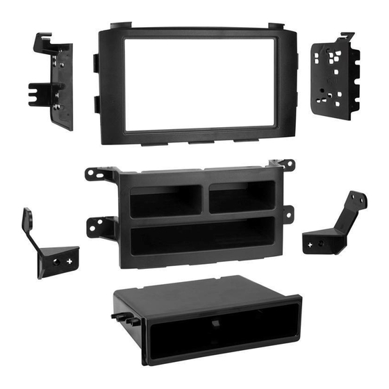
KIT COMPONENTS
• A) Radio trim panel • B) Radio replacement pocket assembly • C) Pocket • D) Radio brackets • E) Climate control brackets
• F) (10) #8 x 3/8" Phillips screws
A
B
Metra. The World's Best Kits.
®
Honda Pilot
(with factory navigation)
KIT FEATURES
• ISO DIN radio provision with pocket
• ISO DDIN radio provision
• Radio replacement pocket assembly
• Textured to match the factory finish
C
D
MetraOnline.com
2006-2008
E
F
© COPYRIGHT 2017 METRA ELECTRONICS CORPORATION
99-7819
I N S TA L L AT I O N I N S T R U C T I O N S
TABLE OF CONTENTS
Dash Disassembly . ..............................................2-3
Kit Preparation . ......................................................4
–ISO DIN radio provision with pocket . .................4
–ISO DDIN radio provision . ....................................5
WIRING & ANTENNA CONNECTIONS (sold separately)
Wiring Harness: 70-1721
Antenna Adapter: 40-HD10
TOOLS REQUIRED
• Panel removal tool • Phillips screwdriver
• Socket wrench
CAUTION!
All accessories, switches, climate
controls panels, and especially air bag indicator
lights must be connected before cycling the
ignition. Also, do not remove the factory radio
with the key in the on position, or while the
vehicle is running.
REV. 10/17/17 INST99-7819
Advertisement
Table of Contents

Subscribe to Our Youtube Channel
Related Manuals for Metra Electronics 99-7819


Summary of Contents for Metra Electronics 99-7819
- Page 1 Also, do not remove the factory radio with the key in the on position, or while the vehicle is running. Metra. The World’s Best Kits. MetraOnline.com ® © COPYRIGHT 2017 METRA ELECTRONICS CORPORATION REV. 10/17/17 INST99-7819...
- Page 2 DASH DISASSEMBLY 1. Remove (2) Philips screws from under 4. Remove (4) screws and remove the NAV the instrument cluster and remove the screen. (Figure C) trim. (Figure A) 5. Remove (4) screws and remove the NAV 2. Unclip and remove the trim panel screen bracket. (Figure D) between the instrument cluster and the NAV screen trim panel. (Figure A) Continued on next page 3. Unclip and remove the NAV screen trim panel. (Figure B) (Figure A) (Figure C) (Figure B) (Figure D) 1.800.221.0932 MetraOnline.com...
- Page 3 DASH DISASSEMBLY 6. Remove the side trim panels from the 8. Remove (4) screws and remove the radio sides of the radio. (Figure E) climate assembly. (Figure G) 7. Remove (4) screws and remove the trim 9. Remove (2) Philips screws to remove the from around the radio including the climate control from the radio/ bracket ashtray. (Figure F) assembly. (Figure H) Continue to Kit Preparation (Figure E) (Figure G) (Figure F) (Figure H) REV. 10/17/2017 INST99-7819...
- Page 4 KIT PREPARATION Attach the climate control brackets to the radio replacement pocket assembly with (2) of the included #8 x 3/8” screws. (Figure A) Place the climate controls between the climate control brackets and secure with the factory hardware. (Figure B) Re-connect the climate control and secure the new assembly into the dash with factory hardware. Continue to Kit Assembly (Figure A) (Figure B) 1.800.221.0932 MetraOnline.com...
- Page 5 KIT ASSEMBLY ISO DIN radio provision with pocket 5. Locate the factory wiring harness and antenna connector in the dash, and 1. Attach the radio brackets to the radio complete all necessary connections to trim panel using (4) #8 x 3/8” Phillips the radio. Metra recommends using the screws supplied. (Figure A) proper mating adapter from Metra and/ 2. Attach the pocket to the bracket or AXXESS. Test the radio for proper assembly using the (4) supplied operation. #8 x 3/8” Phillips screws. (Figure B) 6. Reassemble the dash in reverse order 3. Remove the metal DIN sleeve and trim of disassembly. ring from the aftermarket radio. 4. Slide the radio into the completed (Figure A) (Figure C) assembly, and then secure it to the assembly using the screws supplied with the radio (Figure C). (Figure B) REV. 10/17/2017 INST99-7819...
- Page 6 KIT ASSEMBLY ISO DDIN radio provision 1. Attach the radio brackets to the radio trim panel using (4) #8 x 3/8” Phillips screws supplied. (Figure A) 2. Slide the radio into the completed assembly, and then secure it to the assembly using the screws supplied with the radio. (Figure B) 3. Locate the factory wiring harness and antenna connector in the dash, and complete all necessary connections to the radio. Metra recommends using the proper mating adapter from Metra and/ or AXXESS. Test the radio for proper operation. (Figure B) 4. Reassemble the dash in reverse order of disassembly. (Figure A) 1.800.221.0932 MetraOnline.com...
- Page 7 REV. 10/17/2017 INST99-7819...
- Page 8 Log onto www.installerinstitute.com or call 800-354-6782 for more information and take steps toward a better tomorrow. Metra recommends MECP certified technicians Metra. The World’s Best Kits. MetraOnline.com ® © COPYRIGHT 2017 METRA ELECTRONICS CORPORATION REV. 10/17/17 INST99-7819...
Need help?
Do you have a question about the 99-7819 and is the answer not in the manual?
Questions and answers