Sign In
Upload
Download
Table of Contents
Contents
Add to my manuals
Delete from my manuals
Share
URL of this page:
HTML Link:
Bookmark this page
Add
Manual will be automatically added to "My Manuals"
Print this page
×
Bookmark added
×
Added to my manuals
Manuals
Brands
HP Manuals
Control Unit
83483A
User manual
HP 83483A User Manual
Electrical plug-in module
Hide thumbs
1
2
3
4
5
6
7
8
9
10
Table Of Contents
11
12
13
14
15
16
17
18
19
20
21
22
23
24
25
26
27
28
29
30
31
32
33
34
35
36
37
38
39
40
41
42
43
44
45
46
47
48
49
50
51
52
53
54
55
56
57
58
59
60
61
62
63
64
65
66
67
68
69
70
71
72
page
of
72
Go
/
72
Contents
Table of Contents
Bookmarks
Table of Contents
Certi Cation
Limitation of Warranty
Declaration of Conformity
Safety Symbols
General Safety Considerations
Table of Contents
The Instrument at a Glance
Ordering Information
Menu and Key Conventions
The HP 83483A, 83484A,B and HP 54751A, 54752A,B
The Purpose of the Plug-In Module
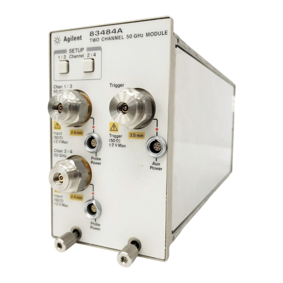
Front Panel of the Plug-In Module
Getting the Best Performance
Installing the Plug-In Module
Trigger
Channel Setup Menu
Electrical Channel Setup Menu
Displaying the Channel Setup Menu
Nnnnnnnnnnnnnnnnnnnnnnn
Display
Nnnnnnnnnnnnnnnnn
Scale
Nnnnnnnnnnnnnnnnnnnn
Offset
Nnnnnnnnnnnnnnnnnnnnnnnnnnnnnnnnnnnnnnnnnnnn
Bandwidth
Nnnnnnnnnnnnnnnnnnnnnnnnnnnnnnnnnnnnnnnnnnnnnnnnnnnnn
Channel Autoscale
Nnnnnnnnnnnnnnnnnnnnnnnnnnnnnnnnnnnnnnnnnnnnnnnnnnnnnnnnnnnnnn
External Scale
Nnnnnnnnnnnnnnnnnnnnnnnnnnnnn
Calibrate
Calibration Status
Calibration Overview
Factory Mainframe Calibrations
Factory Calibration Summary
Current Frame 1Temp Condition
User Calibrations
Electrical Channel User Calibration Summary
Plug-In Module Vertical Calibration
Dark Calibration
Dark Calibration Menu
Channel Skew Calibration
Probe Calibration
External Scale
Electrical Channel Calibrate Menu
Complete Calibration Summary
Speci Cations
If the Plug-In Does Not Operate
Advertisement
Quick Links
Download this manual
User's Guide
HP 83483A, 83484A,B
HP 54751A, 54752A,B
Electrical Plug-In
Module
Table of
Contents
Previous
Page
Next
Page
1
2
3
4
5
Advertisement
Table of Contents
Need help?
Do you have a question about the 83483A and is the answer not in the manual?
Ask a question
Questions and answers
Related Manuals for HP 83483A
Control Unit HP 83487A User Manual
Optical/electrical plug-in module (98 pages)
Control Unit HP HP 83491A User Manual
Clock recovery modules (62 pages)
Control Unit HP 83481A User Manual
Optical/electrical plug-in module (99 pages)
Control Unit HP 83400 Series Getting Started
Lightwave source and receiver modules (77 pages)
Control Unit HP 83484A User Manual
Electrical plug-in module (72 pages)
Control Unit HP 81536A User Manual
Sensor module (30 pages)
Control Unit HP 572018-B21 Specification
For c-class bladesystem (16 pages)
Control Unit HP 81533B User Manual
Optical head interface module and optical heads (52 pages)
Control Unit HP 81520A User Manual
Optical head interface module and optical heads (52 pages)
Control Unit HP HP 81554SM Operating And Programming Manual
Lightwave multimeter source module (30 pages)
Control Unit HP HP 81531A User Manual
Sensor module (34 pages)
Control Unit HP 81531A User Manual
Sensor module (30 pages)
Control Unit HP 81551MM Operating Manual
Lightwave multimeter source module (24 pages)
Control Unit HP 81552SM Operating Manual
Lightwave multimeter source module (26 pages)
Control Unit HP 81553SM Operating Manual
Lightwave multimeter source module (28 pages)
Control Unit HP 81541MM Operating And Programming Manual
Lightwave multimeter source module (22 pages)
This manual is also suitable for:
83484a
83483b
3484b
54751a
54752a
54751b
...
Show all
54752b
Table of Contents
Print
Rename the bookmark
Delete bookmark?
Delete from my manuals?
Login
Sign In
OR
Sign in with Facebook
Sign in with Google
Upload manual
Upload from disk
Upload from URL


Need help?
Do you have a question about the 83483A and is the answer not in the manual?
Questions and answers