
Related Manuals for M2M Easy 2


Summary of Contents for M2M Easy 2
- Page 1 M2M Easy 2 ® Security Communicator Installation Guide for the software v2.1 _____________________________________ Rev: 2.1.2 2014-07-02...
- Page 2 Document specifications ® This documentation was compiled for the M2M Easy 2 Security Communicator device WM Systems LLC. developed by , and contains the step-by-step description of its installation, the program update process and the detailed introduction of the setup parameters necessary for its operation.
-
Page 3: Table Of Contents
5.10 Configuration setup, programming the device ..............46 5.10.1 Opening and displaying configuration files ................ 46 5.10.2 Sending parameters from the PC to the Easy 2..............48 5.10.3 Reading out parameters from the Easy 2 to the PC ............50... - Page 4 SETTING UP THE DEVICE PARAMETERS WITH EASYTERM ......51 6.1 General settings ........................51 6.2 Setup parameters ......................53 6.3 Alarm security settings ....................... 55 6.3 Input settings ........................60 6.3 Output settings ........................63 CONFIGURATION ON SERIAL PORT, TCP PORT ..........72 7.1 Configuration on serial port ....................
-
Page 5: Configuration Possibilities
Chapter 1. Configuration possibilities Software installation and configuration options with Terminal program Local software (RJ11 serial port) EasyTerm refresh with software (RJ11 serial port) Remote software EasyTerm FTP server ( refresh Software and with Terminal software parameter (commands) upload options... -
Page 6: Connectivity
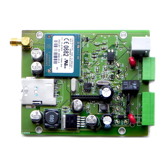
Chapter 2. Connectivity 2.1 Wiring options Input, output connector s 1 – SIM-card holder (push-push, insert) 2 – SMA antenna connector (50 Ohm, male) 3 – PWR: Power supply connector (12VDC) 4 – IN1, IN2: 2x inout line cable connector (for sensors) 5 –... - Page 7 8 – PROG: RJ11 connector (for configuration, software upload) 9 – Service connector (support) 10 – Communication GPRS modem External interface connectors 1– Power chord connector 2 – 2x input connector (operation mode can be selected with jumpers) 3 – 1x output (relay) 4 –...
- Page 8 When it is configured as here below as it can be seen in the picture, then the line #1 (IN1 jumpere: JP1) works in contact input, the input #2 (IN2 jumper: JP2) works as voltage input. In case of voltage input the inputs can be actived with 2-32V DC voltage, other else they are inactivated.
-
Page 9: Installing The Device
2.2 Installing the device Preparation Take the 4 spacer fixing tabs provided with the device, and place them into the PCB holes as shown in the picture. Prepare a screwdriver, the 2 terminal blocks provided with the device, and the stripped wire pair necessary for connection, with appropriate distinctive colors (power connector –... - Page 10 sabotage purposes. This way, it can be used for monitoring the unauthorized opening of the alarm center cover for safety and security reasons (when the magnetic contactor connected to the input line). During the installation process, do not forget to set up the input mode jumper (JP1, JP2). ATTENTION Always turn off the device, and switch off power supply before performing assembly.
- Page 11 The alarm center can be connected to the ALR input via 1 wire pair, thus it will be able to forward its alarm signals to the Easy 2. It is connected with the cable wire pair according to the standard connection shown below.
-
Page 12: Status Leds
LED located above the power supply line indicates the active (closed) position with the appropriate color/light. Example for Easy 2 wiring and installation 2.3 Status LEDs Operation LED status options Function Description Behaviour státusza In case of normal operation for signing the GSM receiving signal strenght –... - Page 13 Output relay Lights: relay closed, not lights: relay opened yellow lights signal MDM RDY Modem status Modem operation blinks blinks intermittently if the modem operates and accessible Status of the alarm center line (tip-ring), Alarm center signs: speaker on, not lights: speaker off or green blinks signal...
- Page 14 This state can be change only when the transmission was succesful, then the LED continously lights until the beginning of the next transmission. Under the inicialization the simultaneous blinkings of the STA and GSM LEDs signs the fault of the SIM card. IN1, IN2: Input #1, input #2 active indication - green When the input is active (if the 2 pair wire closed;...
- Page 15 The LED controlled directly by the GSM module. The exact LED flash-signals can be found int ® he Cinterion „BG2-E AT Command Set” document with the following figure. The following requirements must be considered: not lights: the module has turned off ...
-
Page 16: Operation Requirements
2.4 Operation requirements General conditions 9-24V power supply with adapter, or 12V DC on 230V, or alarm center 12V/24V output Activated SIM card with public access and GPRS data service assured by the Mobile Operator. If it is recommended with private APN access. There can be differences between the Mobile Operator conditions at APN service charges and data traffic unit fees (depend on available rates). - Page 17 ® EasyTerm Downloading the configurator application from our website, at the Downloads / M2M Easy 2 Security Communicator product: http://m2mserver.com/en/downloads ® M2M Easy 2 Security Communicator firmware (system software – uploaded to the ...
-
Page 18: Installation Of The Device
Chapter 3. Installation of the device Easy 2 For the installation follow the next steps. 3.1 Installation steps The device needs protection against unathorized access and wheather conditions. As usual in the security and safety area, that used to place into the security alarm system case or fixed closed to the alarm system to a protected area. - Page 19 Let’s wiring the cables of the monitored input to the required terminal blocks (wire pair) of it (IN1, IN2 title for the input lines) and the output to the OUT titled wire pair. The alarm center has to be wired to the alarm input line (ALR titled). You can setup the meaning of the input line with the jumpers behind the input lines (JP1, JP2).
-
Page 20: Turning On The Device
3.2 Turning on the device When starting the device the next steps are executed: o When the power voltage given the devices turns on. The green PWR LED flashing for a short time, and for a moment the MDM RDY LED also flashes, which signs that the GSM modem was started. -
Page 21: Possible Problems
Example for appropriate operation and successful GPRS communication PWR LED lights (green), STA LED (yellow) sometimes blinks, the GSM LED (red) flashes the GSM signal strength value (between 1 and 8) 3.3 Possible problems 1. When the STA (yellow) and GSM (red) LEDs are bilinking together at the same time then it signes SIM card failure. - Page 22 Malfunction – signed by the LED signals (the GSM and the STAT signed LEDs are blinking together and continuously) ATTENTION When the input or output line wiring is not properly connected or wired the LED signals will not sign the wire problems. The inout/output line LEDs will be continuously lighting IN1, IN2, OUT and ALR titled LEDs), when the wiring was properly done.
-
Page 23: Installing The System Software
Chapter 4. Installing the system software 4.1 Computer connection a.) In case of using USB port When using the converter cable (this is not included in the package), the driver necessary for operating the device via this cable has to be downloaded and installed. ATTENTION It is important that at this time neither the Easy device, nor the USD connector be connected to the computer! -
Page 24: Downloading The Software Components
Because of this, please, check which COM ports are the actual serial port connection points. 4.2 Downloading the software components The accessories necessary for software uploading can be found on the website of WM Rendszerház, within Downloads / M2M Easy 2 Security Communicator: http://www.m2mserver.com/en/downloads... -
Page 25: Identifying Software
Predefined configuration setups for the device. Upload it with the help of the ® EasyTerm program. File: EASY2_V21R01_CFG_EN.cfg c.) Easy 2 Firmware – Easy 2 system software (.BIN) The device can operate with this system software. Download from the website and ® EasyTerm always update to the latest available version. -
Page 26: Checking The Serial Port Connection
Perform connecting and wiring according to the steps previously shown to the terminal blocks (input, output, power, etc.). If it’s necessary connect the alarm system phone line TIP-RING connector to the ALR input line. Easy 2 Place a SIM card activated with a data package into the device. - Page 27 It is neccessary to declare the communication settings: COM port number Baud Rate: 9600 Data Bits: 8 Stop Bits: 1 Parity: None Parity Error Char: 63 Flow control: off...
- Page 28 At the sequence command editor the required commands can be pre-defined in ASCII format. For every sequence line we could give a Name. At the end of the commands a control character must be used. This can be an line termination (code: <CR> ) or carriage return can be used (code: r ) The further details about the software can be found in the 7.1 chapter.
-
Page 29: Easyterm - Configuration, Software Refresh
Chapter 5. EasyTerm: configuration, software refresh The factory default configuration does not contain some operation settings for the Easy2 ® EasyTerm therefore we suggest to setup the parameters with the software before the first usage. 5.1 Introducing the EasyTerm utility ®... -
Page 30: Easyterm Startup
For the previous Easy 1 product we offered to use the HyperTerminal and DR-Term utilities. These are not recommended anymore to use in the case of the Easy 2 device. The EasyTerm gives more comfortable and easy-to-use software solution which approves the whole functionality of all these applications. -
Page 31: Checking Data Connection Settings
The program can be started from the downloaded ZIP package (from our website). You can start it after decompressing the package from a directory with executing the EasyTerm.exe program. EasyTerm You can see the following startup screen when you start the program. - Page 32 Click on the Open button for the connection. Terminal Then in the window (5) the port connection open information appears. 2014.04.28. 12:34:30:open port COM3 2014.04.28. 12:34:32:Serial port opened As it can see the COM3 port was opened for serial port communication. ...
-
Page 33: Checking The Proper Startup Of The Device
When login to the system (with the AT@PD=ABCD command) all debug messages will be banned, what can be enabled only by the EXIT or RESET command. 5.4 Checking the proper startup of the device Easy 2 At the initialization of the device, its software writes the bootloader version and date, and hardware and software versions to the debug port. - Page 34 2014.04.28. 12:47:47:SWVER=2.1R02 2014.04.28. 12:47:47:OK Reads out the SIM card ICC identifier. 2014.04.28. 12:34:35:SIMICC=? 2014.04.28. 12:34:35:SIMICC=8936200003140100131 2014.04.28. 12:34:35:OK Device Information The readout identifiers will be assigned to the window (2) if the a switches were previously enabled. You can monitor the device connection current state at the Status block (3). connecting If the „...
- Page 35 If the „ ” title will be shown then the connection to the device was successful. Easy 2 You have to consider the following point regarding the operation: when the GPRS communication was enabled (GPRSEN parameter) then the internet services will be initialized (TCP listen, primary and secondary server, FTP server).
-
Page 36: Setting Up The Gprs Connection
These steps can be used ONYL FOR THE EARLIER v2.0 BASED SOFTWARE! The refresh must be performed only if a new software version released for the Easy 2 device, when in any case You wanted to refresh the current software to the new release. - Page 37 (2) the SW VER (software version) value that it must be lower then the new one which You wanted to upload. E.g.: Easy 2 when the current software on the device is „SW VER: 2.0r26”, and the uploaded must be at minimal 2.0 R27.
- Page 38 ATTENTION The uploading process takes about 2-3 minutes, which can be seen at the visual process indicator. NEVER STOP, INTERRUPT, OR POWER DOWN the device when the firmware uploading is in progress, because it can cause the malfunction of the device! Terminal After the finish of the uploading when it was successfully done, You can see at the ablakban window (4) the „transfer OK”...
-
Page 39: Firmware Upload, Software Refresh With Ftp Server (From V2.1 Or Newer Software!)
This feature CAN BE USED ONLY WITH THE NEW V2.1 BASES OR NEWER SOFTWARE RELEASES for remote uploading! The refresh must be performed only if a new software version released for the Easy 2 device, when in any case You wanted to refresh the current software to the new release. - Page 40 This function can be used for network installation when an FTP server is available on the network and You want to use it for distributing the software. It is a great way to multiply or mass installations or remote software refresh of the device park tool. EasyTerm ...
- Page 41 Step2 At the part click on the Refresh button then the Start to initiate the upload. The software Easy 2 tries to request info the local public IP address of the PC whereas the can be accessed and fills the other parameters with default values if they were empty.
-
Page 42: Firmware Upload At Serial Port
5.8 Firmware upload at serial port The refresh must be performed only if a new software version released for the Easy 2 device, when in any case You wanted to refresh the current software to the new release. Configuration load ... - Page 43 When the loading process starts at first the Wait for bootloader… messages appears then the device will be restarted with Restart device… message. Soon appears the Sending File, please wait… message, which will be signed by the process indicator. The program Easy 2 sends the firmware to the device.
-
Page 44: Gate Opening
5.9 Gate opening settings Configuration file For configuring the gate opening settings, can be done at the window (5), in the Gate tab selection. The device able to store 125 phone numbers, which can be added Contact list the gate opening function. The phone numbers can be handled as in the system ... - Page 45 The Read button reads back the added and configured numbers. You can add further numbers and continues these until it is necessary with adding the next number by the Add button and repeat with the steps written upper. Select ...
-
Page 46: Configuration Setup, Programming The Device
® EasyTerm is able to load the configuration files, and makes able to modify the Easy 2 parameter settings and save them with sending the settings to the device. These config files (with .CFG extension) also contains all user-specific settings. The configuration can be done with the following steps. - Page 47 The previously saved files can be reloaded later to the application, and Easy 2 send to the device. ATTENTION The changing of the parameter values doesn’t mean that the configured values will be automatically changed on the Easy 2 also. This can be performed to choose the...
-
Page 48: Sending Parameters From The Pc To The Easy 2
5.10.2 Sending parameters from the PC to the Easy 2 ATTENTION Before You change the current configuration or send a parameter value to the Easy 2 device, let’s perform the steps written at the Chapter 5.10.3, then afterall, just save the settings with the save file button. - Page 49 When all parameters have to be choosed, then just choose the Select all button and select the Write config button to send them (all parameter settings) to the device. When sending the changed parameters, the previously used settings will be override on the device.
-
Page 50: Reading Out Parameters From The Easy 2 To The Pc
Terminal has finished You’ll see the „config write completed” message in the window (4). 5.10.3 Readout parameters from the Easy 2 to the PC Easy 2 The device has the configured settings. To readout them just click on the Selected Select all button. -
Page 51: Setting Up The Device Parameters With Easyterm
Chapter 6. Setting the device parameters with EasyTerm 6.1 General settings It is required to configure at least the following parameters for the general operation of the device: APN name (enclosed APN network name - given by the Mobile Operator) ... - Page 52 The Default value coloumn default settings assign the default given and written values which were presented at the current configuration file. Steps to configure the General Settings: Value 1. Give the name to the coloumn whic approved by Your M.O. to access the APN network (like NET or something which can be used), then hit the Enter.
-
Page 53: Setup Parameters
9. To perform and begin the deviceserver communication You have to enable the GPRS connection with the GPRSEN parameter selection and changing its value to Enable. Value 10. Configure the Account as it was gaven by the security surveillance center (like 1201 or similar), then hit the Enter. - Page 54 DNS1= DNS 1* First DNS server IP address os (primary server address DynDNS address for domain address) name service (default value: DNS2= DNS 2* Secondary server (secondary DNS server address address os DynDNS address address) domain name service (default value: SERVER1= Server #1 address* Primary used IP address for...
-
Page 55: Alarm Security Settings
Disabled) (default value: 6.3 Alarm security settings Easy 2 able to transmit events on two channel to the remote surveillance centre: on GPRS network and via voice call. This two channels can be enabled or disabled indepentently. When all the two channels are enabled then the GPRS has priority and the voice call will be activated only if the GPRS transmitting was unsuccessful. - Page 56 Voice call (backup) The voice call operation mode can be enabled/disabled by the BACKUP parameter. By default it is enabled. Life signals All of the two signal transmitting modes are able to send life signals. The life signal is a Contact ID (CID) messages which contains the following parts: Field Account...
- Page 57 Alarm system operation mode Easy 2 Currently the device supports only the Contact ID (CID) protocol when communicating with the alarm system. After pull in the call the alarm system will get a dial tone when a voice call is not in progress.
- Page 58 Alarm Security settings: Comman Parameter name Data Description Type SFUNCT= Event reporting Selection It is possible to define the sequence sending method. At here, the primary secondary sending channels could be defined. Possible values: - Server1, Server2 - Server2, Server1 Server1, (Default value:...
- Page 59 LFFREQ= GPRS Test-heartbeat Number GPRS life signal sending time (sec) interval frequency (Life signal sending second measure-ment unit. interval) In case of thick frequency the devices distributes more data which can be unnecesary in some situations, because it is easy to override the required data packet limit (usually only max.
-
Page 60: Input Settings
Second (Default value: 6.4 Input settings Easy 2 assures 2 input lines. The connectable rising edge to high (L→H) and the descending edge to low (H→L) could indicate the device to generate CID messages in case of these events and transmitting them. - Page 61 SYSL parameter. If nor the SYS1, not the SYSL parameter was not defined the the Easy 2 cannot perform signal transmitting! Contact ID (CID) messages The generated CID messages for the input events the customer identifier (account number) will be selected regarding the following rules: 1.
- Page 62 Input settings: Command Parameter name Data Description Type IDELAY= Input delay (x20msec) Number Pulse width declared to the input line – defined in 20msec bontásban step (Default value: I1INV= Input #1 Inverse Selection Inversion of the input line no. Values: Inverse, Non-Inverse Non-Inverse (Default value: I2INV=...
-
Page 63: Output Settings
mask for the Input line no. 1 (status change). Values: Disabled Disabled message sending, voice call, GPRS signal transmitting enabled Enabled message sending, voice call, GPRS signal transmitting Enabled) (Default value: I2HLEN= Selection Input #2 HL Declared high low enabling mask for the Input line no. - Page 64 OUTHDEL value can be max. 86400 (which means 1 day), but consider that when increasing the parameter value, there could be increased inaccuracy because of the lack of the RTC clock! In Bi-stable mode there is no delay, the opened and closed standing positions can be changed only by the affect of the appropriate trigger (the relay witt change its position only by this).
- Page 65 (Default value: I1ZONE= Input #1 CID zone Number Zone value for the input line no. 1 (Default value: I2EVENT= Input Number CID event code for the input event line no. 1 (Default value: I2PART= Input Number Partition value for the input partition line no.
- Page 66 Voice call notification (ringing) trigger The phone numbers will be activated for affection of the input . The ringing of the active phone numbers will be used from the lower index to the higher, which is independent from that which input activated the current phone number. When the ringing was successful, then the phone numbers for the current input line will be activated.
- Page 67 TEL2= Phone No. #2 Number Phone Number 2: a phone number which will be used primary for notification (SMS message sending) and voice call. the sequence can be used in 15 combination. The choosed sequence mask can be selected that for which numbers valid messaging and in which order.
- Page 68 ATTENTION The calling number display service depends on the mobile operator, therfore it’s important to use the appropriate prefix of the current country when defining a phone number. Consider that the national and international (roaming) prefixes can be different. Input notification parameter settings (SMS message): Command Parameter Name Data...
- Page 69 Example: 15 – 1,2,3,4 which means: all the 4 phone numbers are anebled)) 0 – no phone (Default value: nr. defined I2V= Input Voice Selection Makes a voice call (ringing) for Selected Phone No. the phone nr. 2 in the order that it was defined.
- Page 70 6.7 Remote software refresh settings Remote software updates parameter settings: Command Parameter Name Data Description Type FTPSERVER= FTP server address FTP sserver IP address, e.g.: address 192.168.6.251 (Default value: FTPPORT= FTP server port Number FTP server port number, e.g.: (Default value: FTPFILE= FTP file path Text...
- Page 71 (Default value: 6.10 Important roles In case of modifying the settings check carefully that the parameter values are accomplished for Easy 2 the required settings, before You will send them for the device. When it is important to save to previous settings, then save the configuration with the Save file button to Your computer.
-
Page 72: Configuration On Serial Port, Tcp Port
Maximum command length: 127 characters ATTENTION The first command must be added only after when the Easy 2 device software was already loaded and it is waiting and ready for interactive actions. The login (authentication) can be done with the following commands: AT@PW=password<CR>... - Page 73 Response format for an invalid command: <CR><LF>ERROR<CR><LF> Connection commands: Command Description password Easy 2 AT@PW= Login to command mode, the doe not sent messages ont he serial debug port anymore EXIT Logout command from the command mode, normal operation,...
- Page 74 Status request parameters: Command Desciption SWVER Software version HWID HW identifier IMEI GSM module IMEI identifier SIMICC SIM card ICC identifier IP address (when the GPRS connection was enabled) Received signal strength by the GSM module (RSSI) VBATT Power voltage of the device (unit: V, resolution: 0.033 V) ALARMACC Requesting the last sent used identifier in the send CID message by the alarm system...
- Page 75 Command Description OUTON Bi-stable: Relay conact closed (short) Mono-stable: Starts the timing OUTOFF Bi-stable: Relay contact opened Mono-stable: Stops the timing Control by voicel call – ringing (Gate Opening feature) In mono-stable operation mode the voice call (ringing) initializes the timing, in bi-stable mode affection for the ringing the output changes its status.
- Page 76 GATE GATERM write type commands assures automatic access to the contect list of phone numbers. The GATE<n> read and write commands makes access to the list elements. The <n> values must be between 1 and 125. GATE=<phone_number> For affection of this command the given number will put into the first available entry of the contact list.
-
Page 77: Configuration Through The Tcp Port
Desciption FWLOAD Performing to start firmware refresh 7.2 Configuration through the TCP port Easy 2 is able to receive commands ont he 9998 TCP port. The login and authentication can be performed with this command: AT@PW=<IMEI identifier last 5 character>... -
Page 78: Compatibility
The executable commands and their format is the same as the command which can be performed on the serial port. The format of the responses are the same as the format of the received on-the-fly messages. 7.3 Compatibility M2M Easy 2 Security Communicator ® device assures 100% compatibility with the Digita Receiver ENIGMA II) Furthermore, it is compatible with several type of alarm centers which general uses SIA CID/DTMF communication protocols. -
Page 79: Configuration With Sms Text Messages
Chapter 8. Configuration with SMS text messages 8.1 Configuration with SMS commands ® M2M Easy 2 Security Communicator device can be parametrized also by SMS messages (commands). The SMS content must be considered by the following points: the commands must be used the english alphabetical and numbers only ... - Page 80 When the authentication was unsuccessful then the other part and commands of the SMS message will be not processed too. When the authentication was successful the sender of the SMS message will receive a feedback SMS message immediately after the processing of the SMS. This will be processed in two steps.
- Page 81 Status request: Command Description of the answer Easy 2 INFDEV It will send in an SMS reply the status summarization of the device: account nr. (customer ID), signal strength value, software DEVSTAT version, hardware identifier, device IMEI identifier, SIM card ICC...
- Page 82 ATTENTION The new password for accessing the configuration suggested to performa at the first steps of the configuration! The can be performed by the command then adding the old password (first) then the new password (second). In an SMS message the old and new passwords must be contained in this sequence.
- Page 83 IPPROTO= Text Used communication protocolt type: UDP, TCP Like: UDP SWPROTO= Text Message format protocol communication Values: 1 - WM Alarm 2 - Enigma Like: 2 (Enigma) GPRSEN= Number Enabling GPRS communication Values: 1 = Enabled, the device sends as the Enigma II IP protocol defined on GPRS to the configured server 0 = Disabled, only GSM mode –...
- Page 84 c.) Settings of Inputs: Parameter Max Char Length Parameter Description Name Type IDELAY= Text Pulse width (delay) 20msec resolution which is added to the Input lines. Like: 25 (25x20msec) IXINV= Numeric Inversing the Nr. X Input line, where X can be 1 or 2 (Nr. of Input line) Values: 0 = non inversing 1 = inverted...
- Page 85 IXEVENT= Text Contact ID (CID) Event Codes for the Input Nr. X, where X can be 1, 2, 3 or 4. For the input lines in case of event can be added a CID code (Default Value: IN1: 130, IN2: 110, IN3: 100, IN4: 120) Like: I1EVENT=130 (CID Code 130 for Input 1)
- Page 86 e.) Security & Safety settings (Contact ID, Alarm Center): Parameter Max Char Length Parameter Description Name Type ACCOUNT= Number The customer ID or Account number which were used or sent by the Alarm System. LFFREQ= Number Life signal sending frequency (in seconds) on GPRS.
- Page 87 IOGPRS= Number In case of input signal changes sends rendelt the CID code in a GPRS telegraph Values: 1 = Enabled 0 = Disabled DTMFTIME= Number This parameter is in relation with the alarm centre. The value is by default ’0’, when there is no filtering with DTMF timer, which means that the defense is turned...
-
Page 88: Example For Parameter Setting With Sms Commands
IXON= Text SMS text definition for Input Nr. X in case of enabled input line, where X can be 1 or 2. Like: I1ON=1_ON IXOFF= Text SMS text definition for Input Nr. X in case of disabled input line, where X can be 1 or 2. -
Page 89: Support Availability
9. Support availability Should you have any questions regarding the usage of the device, you can contact us in the following ways: Email: support@m2mserver.com Telephone: +36 20 333 1111 9.1 Support help For identifying the device, please, use the sticker on the PCB, which contains important information to the support staff. -
Page 90: Product Support
9.2 Product support Click the following link to download the available product documentations and software: http://m2mserver.com/en/products/m2m-easy-2-security-communicator The documents and softwares related to the product are available at our website: http://m2mserver.com/en/downloads Online product support can be used at here: http://m2mserver.com/en/product-support... -
Page 91: Legal Notices
10. Legal notices ©2014. WM Systems LLC. The content of this documentation (all information, pictures, tests, descriptions, guides, logos) is under copyright protection. Copying, using, distributing and publishing it is only permitted with the consent of WM Systems LLC., with clear indication of the source. The pictures in the user guide are only for illustration purposes.
Need help?
Do you have a question about the Easy 2 and is the answer not in the manual?
Questions and answers