Table of Contents
Advertisement
MOOG PROPRIETARY AND CONFIDENTIAL INFORMATION
THIS TECHNICAL DATA/DRAWING/DOCUMENT CONTAINS INFORMATION THAT IS PROPRIETARY TO, AND IS THE EXPRESS PROPERTY OF
MOOG INC., OR MOOG INC. SUBSIDIARIES EXCEPT AS EXPRESSLY GRANTED BY CONTRACT OR BY OPERATION OF LAW AND IS RESTRICTED
TO USE BY ONLY MOOG EMPLOYEES AND OTHER PERSONS AUTHORIZED IN WRITING BY MOOG OR AS EXPRESSLY GRANTED BY
CONTRACT OR BY OPERATION OF LAW. NO PORTION OF THIS DATA/DRAWING/DOCUMENT SHALL BE REPRODUCED OR DISCLOSED OR
COPIED OR FURNISHED IN WHOLE OR IN PART TO OTHERS OR USED BY OTHERS FOR ANY PURPOSE W HATSOEVER EXCEPT AS
SPECIFICALLY AUTHORIZED IN WRITING BY MOOG INC. OR MOOG INC. SUBSIDIARY.
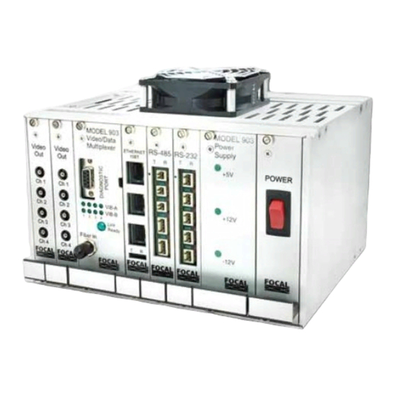
Model 903 High Density (HD)
Fiber Optic Video/Data Multiplexer
(FMB-X-2.5 Version)
User's Guide
Moog Components Group, Halifax Operations
Focal Technologies Corporation
77 Frazee Avenue
Dartmouth, Nova Scotia, Canada B3B 1Z4
Tel: 1-902-468-2263 • Fax: 1-902-468-2249
Email: focal@moog.com • www.moog.com/marine
Report No.:
Revision:
Author(s):
Date of Issue:
903-0628-00
1
A. Cabrera
June 19, 2014
Advertisement
Table of Contents

Related Manuals for Moog Focal 903

Summary of Contents for Moog Focal 903
- Page 1 THIS TECHNICAL DATA/DRAWING/DOCUMENT CONTAINS INFORMATION THAT IS PROPRIETARY TO, AND IS THE EXPRESS PROPERTY OF MOOG INC., OR MOOG INC. SUBSIDIARIES EXCEPT AS EXPRESSLY GRANTED BY CONTRACT OR BY OPERATION OF LAW AND IS RESTRICTED TO USE BY ONLY MOOG EMPLOYEES AND OTHER PERSONS AUTHORIZED IN WRITING BY MOOG OR AS EXPRESSLY GRANTED BY CONTRACT OR BY OPERATION OF LAW.
- Page 2 903-0628-00 Rev. 1 Model 903-HD User's Guide – FMB-X-2.5 REVISION HISTORY Date Details of Revision Author(s) (yyyy-mm-dd) Initial release (based on 903-0624-00) 2014-06-19 REFERENCE DOCUMENTS Document Number Document Title/Description 903-0623-00 Model 903 Fiber Optic Video/Data Multiplexer User's Guide 903-0622-00 Model 903 FMB-X-2.5 Diagnostics Manual 903-0611-00 Model 903 Video/Data Multiplexer Software Manual 903-8xxx-xx...
-
Page 3: Table Of Contents
903-0628-00 Rev. 1 Model 903-HD User's Guide – FMB-X-2.5 TABLE OF CONTENTS Introduction ..........................1-1 System Overview ......................... 2-1 Multiplexer Systems ......................2-1 Rack Configuration ......................2-4 2.2.1 4VID Console and Remote Modules............... 2-4 2.2.2 8VID Console and Remote Modules............... 2-5 2.2.3 Channel Mapping .................... - Page 4 903-0628-00 Rev. 1 Model 903-HD User's Guide – FMB-X-2.5 7.1.3 Using Diagnostic Software ..................7-1 Most Common Problems ....................7-2 7.2.1 Most Common Video Problems ................7-2 7.2.2 Most Common Data Problems ................7-2 7.2.3 Most Common Optical Problems ................7-2 Possible problems, symptoms, and solutions ..............
- Page 5 903-0628-00 Rev. 1 Model 903-HD User's Guide – FMB-X-2.5 LIST OF FIGURES Figure 2-1: Model 903-HD Multiplexer – I/O Ports (4VID System) ..............2-2 Figure 2-2: Model 903-HD Multiplexer – I/O Ports (8VID System) ..............2-3 Figure 2-3: Model 903-HD Mux Front Panel View – Card Configuration (4VID)..........2-4 Figure 2-4: Model 903-HD Mux Front Panel View –...
- Page 6 903-0628-00 Rev. 1 Model 903-HD User's Guide – FMB-X-2.5 LIST OF TABLES Table 2-1: Model 903-HD Systems – Signal Types Supported ..............2-1 Table 2-2: Typical Remote-to-Console Channel Mapping (4VID System) ............ 2-7 Table 2-3: Typical Remote-to-Console Channel Mapping (8VID System) ............ 2-9 Table 3-1: FMB-X-2.5 Front Panel LEDs .....................
- Page 7 903-0628-00 Rev. 1 Model 903-HD User's Guide – FMB-X-2.5 Safety Precautions The following safety precautions should be observed before using this product. This product is intended for use by qualified personnel who recognize shock hazards and are familiar with safety precautions required to avoid possible injury.
- Page 8 903-0628-00 Rev. 1 Model 903-HD User's Guide – FMB-X-2.5 ACRONYMS AND ABBREVIATIONS Adaptable Interface Board Avalanche Photodiode CWDM Coarse Wavelength Division Multiplexer Data Interface Board Emitter Coupled Logic Electronic Industries Association Electrostatic Discharge Fiber (Optic) Multiplexer Board FORJ Fiber Optic Rotary Joint FPGA Field Programmable Gate Array Gbps...
-
Page 9: Introduction
903-0628-00 Rev. 1 Model 903-HD User's Guide – FMB-X-2.5 1.0 Introduction Focal's Model 903 is a video/data multiplexer and fiber optic transmission system designed for Remotely Operated Vehicle (ROV) applications. The Model 903 uses Time Division Multiplexing (TDM) and Wavelength Division Multiplexing (WDM) to provide high multiplexing density in a compact, low-power package. -
Page 10: System Overview
903-0628-00 Rev. 1 Model 903-HD User's Guide – FMB-X-2.5 2.0 System Overview This document contains information about 903 high density systems based on FMB-X-2.5 boards (fiber multiplexer boards with optical link running at 2.5 Gbaud). A high density multiplexer system consists of a Model 903-HD high density remote module (vehicle or ROV end) and a standard Model 903 console module (surface or shipboard end). -
Page 11: Figure 2-1: Model 903-Hd Multiplexer - I/O Ports (4Vid System)
903-0628-00 Rev. 1 Model 903-HD User's Guide – FMB-X-2.5 The figure below shows the I/O ports and optical connections of a 903-HD 4VID system. CONSOLE MODULE 4 x VIDEO 1 x 10/100 MBPS 4 x SERIAL* 4 x RS-232* OUTPUT (B) ETHERNET/ *AIB PLUG-IN, RECONFIGURABLE DIAGNOSTIC... -
Page 12: Figure 2-2: Model 903-Hd Multiplexer - I/O Ports (8Vid System)
903-0628-00 Rev. 1 Model 903-HD User's Guide – FMB-X-2.5 The figure below shows the I/O ports and optical connections of a 903-HD 8VID system. CONSOLE MODULE 4 x VIDEO 1 x 10/100 MBPS 4 x SERIAL* 4 x RS-232* 4 x SERIAL* 4 x RS-232* OUTPUT (A) ETHERNET/... -
Page 13: Rack Configuration
903-0628-00 Rev. 1 Model 903-HD User's Guide – FMB-X-2.5 Rack Configuration This section provides information about the remote and console module configuration of the 4VID and 8VID systems covered in this document. Slots in each rack are referenced by letter, per the installation drawings 903-8xxx-xx. -
Page 14: 8Vid Console And Remote Modules
903-0628-00 Rev. 1 Model 903-HD User's Guide – FMB-X-2.5 2.2.2 8VID Console and Remote Modules The 8VID console and remote front panel views are shown in the figure below. This figure also shows a brief description of each card and the card’s slot position/letter. Note that the as-installed configuration may differ if cards, such as the AIB-plugins, have been changed to accommodate new interface requirements. -
Page 15: Channel Mapping
903-0628-00 Rev. 1 Model 903-HD User's Guide – FMB-X-2.5 2.2.3 Channel Mapping 2.2.3.1 4VID Remote-to-Console Channel Mapping The following figure shows the remote-to-console channel mapping of a 903-HD 4VID system. REMOTE BOTTOM VIEW MODULE (12 HP I/O BOX) HDB-TX-B RS-232 FOCAL 4 x SERIAL (AIB PLUG-IN) 4 x VIDEO... -
Page 16: Table 2-2: Typical Remote-To-Console Channel Mapping (4Vid System)
903-0628-00 Rev. 1 Model 903-HD User's Guide – FMB-X-2.5 A complete mapping of remote to console channels of a 4VID system is given in the following table. Table 2-2: Typical Remote-to-Console Channel Mapping (4VID System) Remote Module Console Module Typical Configuration Signal Type &... -
Page 17: Figure 2-6: Console And Remote Modules (8Vid) Showing Slot Pairings For Video And Data
903-0628-00 Rev. 1 Model 903-HD User's Guide – FMB-X-2.5 2.2.3.2 8VID Remote-to-Console Channel Mapping The following figure shows the remote-to-console channel mapping of a 903-HD 8VID system. BOTTOM VIEW REMOTE 16 HP I/O BOX MODULE HDB-TX-A HDB-TX-B RS-232 RS-232 FOCAL FOCAL 4 x SERIAL (AIB PLUG-IN) 4 x RS-232... -
Page 18: System Expansion
903-0628-00 Rev. 1 Model 903-HD User's Guide – FMB-X-2.5 A complete mapping of remote to console channels of an 8VID system is given in the following table. Table 2-3: Typical Remote-to-Console Channel Mapping (8VID System) Remote Module Console Module Typical Configuration Signal Type &... -
Page 19: Optical Configuration
903-0628-00 Rev. 1 Model 903-HD User's Guide – FMB-X-2.5 Optical Configuration The optical configuration of a 4VID and 8VID dual fiber systems is shown in the figure below. REMOTE MODULE FMB-X-2.5-R RX 1550 nm LC-LC ST (FC OPTIONAL) TXVR SPLITTER TX 1310 nm FIBER SYSTEM (FORJ, FIBER, CONNECTORS, JUNCTION BOXES) -
Page 20: Backwards Compatibility
903-0628-00 Rev. 1 Model 903-HD User's Guide – FMB-X-2.5 Backwards Compatibility The FMB-X-2.5 is not backwards compatible with the FMB-VTX, FMB-VRX or GLINK FMB-X cards. Both remote and console FMBs must be replaced with the FMB-X-2.5 when upgrading. All FMB-X-2.5 cards operate at 2.5 Gbaud on uplink (1310 nm) and downlink (1550 nm) and are compatible with existing video cards, data cards, and high speed racks. -
Page 21: Fiber Multiplexers And Backplanes
903-0628-00 Rev. 1 Model 903-HD User's Guide – FMB-X-2.5 3.0 Fiber Multiplexers and Backplanes Fiber Multiplexer Boards (FMBs) are used to combine all of the video, Ethernet, and data signals into a single optical link and then regenerate the original copper signals at the other end of the system. Backplane cards are used to connect all of the Model 903 cards together within remote or console modules. -
Page 22: Figure 3-2: Remote Fmb-X-2.5 Plan View
903-0628-00 Rev. 1 Model 903-HD User's Guide – FMB-X-2.5 LEDs on the front panel match those described in the console FMB-X-2.5 section and allow direct monitoring of the optical link status (LINK), optical receive power (FO-RX), and the status (STAT) of the on-board diagnostics. -
Page 23: Figure 3-3: Console Fmb-X-2.5 Front Panel
903-0628-00 Rev. 1 Model 903-HD User's Guide – FMB-X-2.5 3.1.2 Console FMB-X-2.5 Card P/N 903-5083-00 The front panel view of the console FMB-X-2.5 is shown in the figure below. Redundant ST fiber connectors are accessible as straight bushings on the front panel marked "F1" and "F2". An internal fiber switch chooses one of the fibers for the optical link, either automatically or manually via the front panel toggle switch. -
Page 24: Figure 3-4: Fmb-X-2.5 Rs-232 Diagnostic Cable: 1/8" (3.5 Mm) Stereo To Db9F
903-0628-00 Rev. 1 Model 903-HD User's Guide – FMB-X-2.5 Description STAT (Status) LED is green when on-board diagnostic readings are within expected values. The STAT LED is orange (warning) if any of the on-board diagnostic readings are close to an alarm state. -
Page 25: Remote Fmb-X-2.5
903-0628-00 Rev. 1 Model 903-HD User's Guide – FMB-X-2.5 The FMB-X-2.5 also sounds a continuous audible alarm when an optical link fails in AUTO mode, even if the other fiber has a valid link. This informs the operator of a fiber fault that otherwise might not be noticed, as the switchover from one fiber to the other is often seamless. -
Page 26: Backplanes (-X Type) And Racks
903-0628-00 Rev. 1 Model 903-HD User's Guide – FMB-X-2.5 Backplanes (-X Type) and Racks BP P/N 903-7212-00 for 4VID 903-HD Remote system BP P/N 903-7213-00 for 4VID 903 Std. Console system BP P/N 903-7207-00 for 8VID 903-HD Remote system BP P/N 903-7210-00 for 8VID 903 Std. Console system The backplane cards are used to connect all the Model 903 cards and PSU modules together to make up a Model 903 system. -
Page 27: Standard -X Backplanes
903-0628-00 Rev. 1 Model 903-HD User's Guide – FMB-X-2.5 3.2.1 Standard -X Backplanes Card P/N: 903-7213-00; 903-7210-00 The standard -X backplanes described in this section are used on the 4VID (BP P/N: 903-7213-00, 28 HP) and 8VID (BP P/N: 903-7210-00, 44 HP) console modules. Assembly views of a 28 HP -X backplane PCB (CBP-121-XR/XC) and a 44 HP -X backplane PCB (CBP-241-XR/XC) are given in Figure 3-6 and Figure 3-7 respectively. -
Page 28: Figure 3-6: 28 Hp -X Console Backplane (Cbp-121-Xc)
903-0628-00 Rev. 1 Model 903-HD User's Guide – FMB-X-2.5 PRIMARY FUSE (F1) 903-7213-00 28 HP “-X” BACKPLANE ASSEMBLY SLOTS: 1 x VIDEO, 1 x FMB, 2 x DATA, 1 x PSU 3 x M2.5X16mm CHEESE HD SS SLOTTED SCREWS 903-0122-01 POWER COVER 903-0123-00 INSIDE POWER COVER... -
Page 29: Figure 3-7: 44 Hp -X Console Backplane (Cbp-241-Xc)
903-0628-00 Rev. 1 Model 903-HD User's Guide – FMB-X-2.5 903-0123-00 INSIDE POWER COVER 903-7210-00 PRIMARY FUSE (F1) 44 HP BACKPLANE -X ASSEMBLY SLOTS: 2 X VIDEO, 1 X FMB, 4 X DATA, 1 X PSU 3 x M2.5X16mm CHEESE HD SS SLOTTED SCREWS 903-0122-00 POWER COVER... -
Page 30: High Density -X Backplanes
903-0628-00 Rev. 1 Model 903-HD User's Guide – FMB-X-2.5 3.2.2 High Density -X Backplanes Card P/N: 903-7212-00 (12 HP BP); 903-7207-00 (16 HP BP) The high density -X backplanes described in this section are used on the 4VID (12 HP BP P/N: 903-7212-00) and 8VID (16 HP BP P/N: 903-7207-00) remote modules. -
Page 31: Figure 3-9: 16 Hp High Density Remote Backplane Pcba (+24 Vdc Input)
903-0628-00 Rev. 1 Model 903-HD User's Guide – FMB-X-2.5 PROGRAMMING HEADER (FACTORY USE) FAN HEADER PIN 1 = + 24 VDC OUT PRIMARY INPUT PIN 2 = DGND PIN 1 = DGND PIN 2 = +24 VDC SPARE PRIMARY FUSE PRIMARY FUSE 0454005, 5 A SMT, 0454005, 5 A SMT,... -
Page 32: Power Supply
903-0628-00 Rev. 1 Model 903-HD User's Guide – FMB-X-2.5 Power Supply The 4VID and 8VID systems use the power supplies described in the table below. Table 3-5: Typical Power Supplies for 903 Console and Remote Systems Power Supply Description System End AC Module (PSU) 115/230 VAC, 60W, 47-63 Hz Auto-ranging Console... -
Page 33: Figure 3-10: Power Connectors Location (4Vid And 8Vid Systems)
903-0628-00 Rev. 1 Model 903-HD User's Guide – FMB-X-2.5 Console (4VID) Console (8VID) POWER SWITCH AC POWER ENTRY Remote (4VID) Remote (8VID) DGND +24 VDC DC POWER IN Figure 3-10: Power Connectors Location (4VID and 8VID Systems) Focal Technologies Corp. Page 3-13... -
Page 34: Interface Cards
903-0628-00 Rev. 1 Model 903-HD User's Guide – FMB-X-2.5 4.0 Interface Cards Interface cards are part of a 903 system and they consist of the following types: Video - Video signals are unidirectional. There are video input cards for the remote module and video output cards for the console module. -
Page 35: High Density Board (Hdb-Tx)
903-0628-00 Rev. 1 Model 903-HD User's Guide – FMB-X-2.5 High Density Board (HDB-TX) Card P/N 903-5006-00 (Remote Only) The remote high density board (HDB-TX) provides interfaces for four video channels, four dedicated RS-232 channels, and four adaptable interface board (AIB) plug-in modules, which are available for a variety of signals, including RS-232, RS-485/422, Tritech ARCNET, hydrophones, CAN bus and analog sonars. -
Page 36: Data Channels
903-0628-00 Rev. 1 Model 903-HD User's Guide – FMB-X-2.5 For 4VID and 8VID systems with FMB-X-2.5 and backplane -X cards installed, the diagnostics software at the surface can monitor the status of the HDB-TX card, including card assembly information, such as serial number. -
Page 37: Figure 4-2: Hdb-Tx Pcb And Connector Location
903-0628-00 Rev. 1 Model 903-HD User's Guide – FMB-X-2.5 DATA I/O VIDEO INPUT CONNECTORS CONN. 4 X AIB PLUG-IN ALIGNMENT DOTS AIB PLUG-IN MODULE HEADERS BACKPLANE CONNECTOR Figure 4-2: HDB-TX PCB and Connector Location Focal Technologies Corp. Page 4-4... -
Page 38: Figure 4-3: Hdb-Tx Block Diagram
903-0628-00 Rev. 1 Model 903-HD User's Guide – FMB-X-2.5 Figure 4-3: HDB-TX Block Diagram Focal Technologies Corp. Page 4-5... -
Page 39: Data Input/Output Module (I/O-Box)
903-0628-00 Rev. 1 Model 903-HD User's Guide – FMB-X-2.5 4.1.3 Data Input/Output Module (I/O-Box) Card P/N 903-6716-01 (I/O-Box B) Card P/N 903-6716-03 (I/O-Box A) The high density remote module uses a compact input/output box (I/O-Box) on the bottom of the rack to provide access connectors, signal protection, and signal activity LED indicators for the data channels on the HDB-TX boards. -
Page 40: Table 4-1: Aib Plug-In Modules And I/O-Box Connector Pin Assignments (Typ 4Vid And 8Vid Systems)
903-0628-00 Rev. 1 Model 903-HD User's Guide – FMB-X-2.5 Installation Note: Headers for the external connections are all four-pin, right-angled 733 series WAGO connectors. Mating WAGO connectors, P/N 733-104, are supplied with the system. Pin locations of the WAGO headers are shown in the figure below. -
Page 41: Video Cards
903-0628-00 Rev. 1 Model 903-HD User's Guide – FMB-X-2.5 Video Cards 4.2.1 VIB-X Video Board Card P/N 903-0014-00 (Remote), 903-0015-00 (Console) The VIB-X video interface board is a generic, 4-channel video card for use with Model 903 multiplexer systems. The VIB-X video interface board is configured with four SMB video jacks on the front panel, per Figure 4-5. This 3U Eurocard is switch configured as either a video input card, used in the remote or subsea multiplexer module, or a video output card, used in the console or surface multiplexer module. -
Page 42: Figure 4-6: Block Diagram Of Vib-X Card
903-0628-00 Rev. 1 Model 903-HD User's Guide – FMB-X-2.5 FRONT PANEL CONNECTORS INPUT FILTER ANALOG SWITCH OUTPUT FILTER INPUT FILTER ANALOG SWITCH OUTPUT FILTER FPGA INPUT FILTER ANALOG SWITCH OUTPUT FILTER INPUT FILTER BACKPLANE ANALOG HEADER SWITCH OUTPUT FILTER Figure 4-6: Block Diagram of VIB-X Card Note: VIB-X cards shipped before August 2011 (cards with SN <... -
Page 43: Table 4-2: Vib-X Card Configuration Settings (Switch Sw3)
903-0628-00 Rev. 1 Model 903-HD User's Guide – FMB-X-2.5 4.2.1.2 Configuration Settings The VIB-X is configured as a remote (video input) or console (video output) using switch SW3, as shown in Figure 4-7 and Table 4-2. Circuit 1 is used to set the card as video input or output and circuit 2 is used for setting normal operation (mux mode, default) or for factory test options (test mode). -
Page 44: Figure 4-7: Vib-X Plan View
903-0628-00 Rev. 1 Model 903-HD User's Guide – FMB-X-2.5 Figure 4-7: VIB-X Plan View Fuses on the rails from the backplane provide over-current protection near the 96-pin DIN 41612 connector at the back of the card, per Figure 4-7. Fuse F1 is a 3A fuse on the +5 V supply rail and fuse F2 is a 1A fuse on the -12 V rail, which is used to generate -5 V on the board. -
Page 45: Data Cards
903-0628-00 Rev. 1 Model 903-HD User's Guide – FMB-X-2.5 Data Cards Data cards are typically bidirectional, with some exceptions. Most data cards are interchangeable between the remote and console module. 4.3.1 AIB-4 - Adaptable Interface Board Card P/N 903-5003-00 (Motherboard) The Adaptable Interface Board (AIB-4) provides four generic channels of data with four sockets that may be populated with any mixture of available plug-in modules. -
Page 46: Figure 4-9: Adaptable Interface Board (Aib-4) Pcb
903-0628-00 Rev. 1 Model 903-HD User's Guide – FMB-X-2.5 The following figure shows the AIB motherboard. ALIGNMENT DOTS (X4) CH4 to CH1 (left to right) Figure 4-9: Adaptable Interface Board (AIB-4) PCB Focal Technologies Corp. Page 4-13... -
Page 47: Figure 4-10: Block Diagram Of Adaptable Interface Board (Aib-4)
903-0628-00 Rev. 1 Model 903-HD User's Guide – FMB-X-2.5 The following figure shows the block diagram for the AIB motherboard. Figure 4-10: Block Diagram of Adaptable Interface Board (AIB-4) Focal Technologies Corp. Page 4-14... -
Page 48: Plug-In Modules
903-0628-00 Rev. 1 Model 903-HD User's Guide – FMB-X-2.5 4.3.2 Plug-In Modules A variety of plug in modules are available for use with the AIB-4 cards. When installing the modules, ensure the connector marked by the white dot on the module PCB is mated with the corresponding header marked with a white dot on the AIB motherboard. -
Page 49: Figure 4-11: Aib Rs-232/Trigger Plug-In Module
903-0628-00 Rev. 1 Model 903-HD User's Guide – FMB-X-2.5 4.3.3 RS-232 Plug-In (AIB-232/TRIGGER) Card P/N 903-0251-00 (AIB-232) Card P/N 903-0251-01 (AIB-TRIG) The AIB-232 plug-in module, which supports RS-232, is shown below in the figure below. No jumper or switch settings are required since the board is used solely for RS-232 data at rates up to 120 kbaud. In addition to the ultra-fast fuses on the AIB-4 motherboard, protection for RS-232 inputs and outputs includes transient voltage suppressors and opto-isolators. -
Page 50: Rs-485/422/Ttl Plug-In (Aib-485)
903-0628-00 Rev. 1 Model 903-HD User's Guide – FMB-X-2.5 4.3.4 RS-485/422/TTL Plug-In (AIB-485) Card P/N 903-0252-00 The AIB-485 plug-in module, which supports RS-485, RS-422, and TTL, is shown below in Figure 4-12. In addition to the ultra-fast fuses on the AIB-4 motherboard, protection for RS-485/422/TTL inputs and outputs includes transient voltage suppressors and opto-isolators. -
Page 51: Figure 4-13: Aib Rs-422 Interface Schematic
903-0628-00 Rev. 1 Model 903-HD User's Guide – FMB-X-2.5 Figure 4-13: AIB RS-422 Interface Schematic Full duplex communication runs transmit and receive on separate conductors, thus autosense is not required. The AIB modules support full duplex transmission as either RS-422 or TTL data. Connector pin designations for the WAGO connectors are given in the table below with default configuration shaded. -
Page 52: Table 4-7: Configuration Settings For Aib Rs-485 Module (Defaults Shaded)
903-0628-00 Rev. 1 Model 903-HD User's Guide – FMB-X-2.5 Table 4-7: Configuration Settings for AIB RS-485 Module (Defaults Shaded) AUTOSENSE MODE CONFIGURATION FUNCTION SW3:1 SW3:2 SW4:1 SW4:2 Full Duplex Simplex Tx Half Duplex (Autosense) Simplex Rx AUTOSENSE BAUD RATE FOR SW5 DIP SWITCH BAUD RATE CCT# 9600... -
Page 53: Tritech Sonar Arcnet Plug-In (Aib-Arcnet)
903-0628-00 Rev. 1 Model 903-HD User's Guide – FMB-X-2.5 4.3.5 Tritech Sonar ARCNET Plug-In (AIB-ARCNET) Card P/N 903-0261-00 The AIB-ARCNET plug-in module, which supports the version of ARCNET used by sonars manufactured by Tritech International Ltd., is shown in the figure below. In addition to the ultra-fast fuses on the AIB-4 motherboard, protection for Tritech inputs and outputs includes transient voltage suppressors and AC-coupled isolation through capacitors and transformers. -
Page 54: Table 4-9: Aib-Arcnet Pin Designations
903-0628-00 Rev. 1 Model 903-HD User's Guide – FMB-X-2.5 The default settings illustrated in the shaded rows of Table 4-8 are typically used for systems with short cables, i.e. a few meters, between the sonar components and the multiplexer modules: Short Cables (default) Sonar Head No terminator... -
Page 55: Hydrophone/Analog Plug-In (Aib-Hydro)
903-0628-00 Rev. 1 Model 903-HD User's Guide – FMB-X-2.5 4.3.6 Hydrophone/Analog Plug-In (AIB-HYDRO) Card P/N 903-0244-00 (AIB-HYDRO, surface) Card P/N 903-0244-02 (AIB-HYDRO, subsea) The AIB-HYDRO hydrophone plug-in module, shown in the figure below, is suitable for use with many hydrophones and other types of low-level analog signals. The board is used at both ends of the system and must be jumper configured, typically, as an input for the remote (subsea) module or as an output for the console (surface) module per the settings in Table 4-10. -
Page 56: Table 4-12: Aib-Hydro Pin Designations
903-0628-00 Rev. 1 Model 903-HD User's Guide – FMB-X-2.5 Although the card is configured to operate with two-wire, un-amplified hydrophone inputs, the hydrophone plugin may be factory modified to provide +12V to an external hydrophone pre-amplifier on a third conductor and bypass the gain of the internal pre-amplifier. -
Page 57: Figure 4-16: Ms-900 Plug-In Module (Top View)
903-0628-00 Rev. 1 Model 903-HD User's Guide – FMB-X-2.5 4.3.7 MS-900 Analog Sonar Plug-In (AIB-MS900) Card P/N 903-0250-00 (AIB-MS900) Card P/N 903-0250-01 (AIB-MS900L modified for low frequency (LF)) The MS900 Analog Sonar Interface AIB plug-in (AIB-MS900) is compatible with the analog telemetry used by the Mesotech MS900 sonar system. -
Page 58: Canbus Plug-In (Aib-Canbus)
903-0628-00 Rev. 1 Model 903-HD User's Guide – FMB-X-2.5 4.3.8 CANBUS Plug-In (AIB-CANBUS) Card P/N 903-0297-00 The CAN bus interface AIB plug-in (AIB-CANBUS), as shown in the figure below, provides transparent extension of CAN 2.0A and 2.0B over the fiber optic multiplexer system. Each AIB card acts as a node on the local CAN bus, handling media access and packet acknowledgements. -
Page 59: Table 4-14: Can Speed Settings
903-0628-00 Rev. 1 Model 903-HD User's Guide – FMB-X-2.5 For real-time control systems, average bus loads above 30% are not recommended due to the non-linear increase in latency inherent with contention based protocols. For non-critical applications, average bus loads should be kept below 50% to maintain good performance. LEDs on the AIB-CANBUS card may be used for diagnostics during bench testing. -
Page 60: Figure 4-18: Wago 4-Pin Header
903-0628-00 Rev. 1 Model 903-HD User's Guide – FMB-X-2.5 Pin connections for the WAGO connector used with the plug-in are shown in the table below. Typically shielded, impedance controlled (120 ohm) twisted pair cabling is required to maintain signal quality. Figure 4-18: WAGO 4-Pin Header Table 4-15: AIB-CANBUS Pin Designations Designation... -
Page 61: Fiber Optics
903-0628-00 Rev. 1 Model 903-HD User's Guide – FMB-X-2.5 5.0 Fiber Optics Safety Lasers used in the Model 903 are Class I laser products. No control measures or warning labels are required, although any needless exposure of the eye should be avoided as a matter of good practice and fiber connectors should never be viewed with optical magnification unless all sources are disconnected. -
Page 62: Table 5-1: Typical Rov System Power Budget
903-0628-00 Rev. 1 Model 903-HD User's Guide – FMB-X-2.5 Table 5-1: Typical ROV System Power Budget Fiber Loss 0.4 dB/km @ 1310 nm, 0.3 dB/km @ 1550 nm Connector (ST/PC) 0.3 dB/conn FORJ Loss (Max.) 4.0 dB LINK VIDEO/DATA DATA (Uplink) (Downlink) Optical Data Rate... -
Page 63: Fiber Handling Guidelines
903-0628-00 Rev. 1 Model 903-HD User's Guide – FMB-X-2.5 Fiber Handling Guidelines 1. Observe the bend radius of fiber optic cables at all times When mounting, disassembling, or reassembling the cards, ensure that no fibers are subjected to bends in excess of those held by the natural routing of the fibers. The minimum bend radius of the fibers should generally be no less than 25 mm, though single loops may be less than this –... -
Page 64: Figure 5-2: Lc Connector
903-0628-00 Rev. 1 Model 903-HD User's Guide – FMB-X-2.5 Figure 5-2 shows an LC connector which is a small form-factor fiber optic connector that uses a 1.25 mm ferrule and incorporates a push-and-latch design similar to an RJ-45 connector. Figure 5-3 shows an ST fiber optic connector that uses a 2.5 mm ferrule. -
Page 65: Installation And Operation
903-0628-00 Rev. 1 Model 903-HD User's Guide – FMB-X-2.5 6.0 Installation and Operation Mounting The console module is intended to be rack-mounted with the side flanges. Extender pieces are available for mounting to a standard 19” equipment rack. Alternatively, the side flanges may be removed to allow use of the four mounting holes with installed PEM nuts on each side plate. -
Page 66: Figure 6-2: Exploded View Of A Model 903 4Vid Console Card Cage
903-0628-00 Rev. 1 Model 903-HD User's Guide – FMB-X-2.5 The figure below shows an exploded view of a 4VID console module. 4X #6-32X1.375" PAN HEAD SS SLOTTED SCREWS 903-0050-00 3U-160 SUB-RACK STANDARD, CONSOLE 903-0100-50 BACK COVER TOP RAIL 10X M2.5X16mm CHEESE HEAD SS SLOTTED SCREWS 903-0102-00 BACK COVER... -
Page 67: Figure 6-3: Side View Of Typical 16 Hp Model 903-Hd Remote Card Cage
903-0628-00 Rev. 1 Model 903-HD User's Guide – FMB-X-2.5 The high density remote modules are intended to be mounted in a user-supplied rack installed in the ROV electronics pressure case. The boards and backplane adhere dimensionally to the Eurocard standard and should be installed in compatible rack of this type. -
Page 68: Cooling
903-0628-00 Rev. 1 Model 903-HD User's Guide – FMB-X-2.5 The figure below shows an exploded view of a Model 903 high density 4VID remote module. 4X #6-32X1.375" PAN HEAD SS SLOTTED SCREWS 903-0061-01 3U-160 SUB-RACK, 12HP 2X M2.5X10 CHEESE HEAD SS SLOTTED SCREWS 903-0174-00 BACK COVER... -
Page 69: Diagnostics
903-0628-00 Rev. 1 Model 903-HD User's Guide – FMB-X-2.5 Diagnostics Model 903 system diagnostics are available via the 10/100 Mbps Ethernet port (RJ-45) or RS-232 serial port (3.5 mm stereo jack) on the front panel of the FMB-X-2.5 cards. Ethernet diagnostics are available as Modbus TCP/IP or through an embedded web server. Diagnostic packets are handled as low priority and must be polled by an external computer. -
Page 70: Bench Test For Model 903 Systems
903-0628-00 Rev. 1 Model 903-HD User's Guide – FMB-X-2.5 Bench Test for Model 903 Systems BASIC LINK OPERATION (FMBs) 1. Basic operation of the uplink (remote to console) and downlink (console to remote) can be verified in a bench test simply by connecting the test jumper and the 10 dB attenuator supplied between a bushing on the remote FMB-X-2.5 turret and a bushing (F1 or F2) on the console FMB-X-2.5. -
Page 71: Figure 6-6: Power Budget Test Setup - Link Threshold Measurement
903-0628-00 Rev. 1 Model 903-HD User's Guide – FMB-X-2.5 Figure 6-6: Power Budget Test Setup – Link Threshold Measurement 3. Disconnect the end of the VOAT that is connected to the console FMB-X-2.5 and measure the optical power (P2) received (received sensitivity) by connecting that end of the VOAT to the optical power meter. -
Page 72: Maintenance
903-0628-00 Rev. 1 Model 903-HD User's Guide – FMB-X-2.5 The Model 903 diagnostics software is also helpful during bench testing. Presence of data errors on the program’s display screen may be used instead of the “Link” LEDs to determine the receiver thresholds. This provides a more accurate power budget, since as received power drops, errors occur in the data frames before synchronization is lost. -
Page 73: Model 903 Board Handling
903-0628-00 Rev. 1 Model 903-HD User's Guide – FMB-X-2.5 Model 903 Board Handling The Model 903 includes several densely populated Printed Circuit Board Assemblies (PCBAs). Although these boards are all conformally coated, care must still be taken while handling the boards to ensure the PCBAs are kept clean and free from electrostatic discharge (ESD). -
Page 74: Troubleshooting
903-0628-00 Rev. 1 Model 903-HD User's Guide – FMB-X-2.5 7.0 Troubleshooting System Verification 7.1.1 Initial Checks Ensure cards installed and configured as per installation drawing. Ensure correct input power is supplied and verify the primary fuse is not open. ... -
Page 75: Most Common Problems
903-0628-00 Rev. 1 Model 903-HD User's Guide – FMB-X-2.5 Most Common Problems 7.2.1 Most Common Video Problems Improper impedance matching (75 ohms) or missing ground connection. Video signal “too hot”, i.e. >> 1 Vpp nominal. (Camera outputs may be set to drive long copper cables.) ... -
Page 76: Possible Problems, Symptoms, And Solutions
903-0628-00 Rev. 1 Model 903-HD User's Guide – FMB-X-2.5 Possible problems, symptoms, and solutions The following is a table outlining possible problems, symptoms, and solutions for Model 903: SYMPTOM POSSIBLE PROBLEM POTENTIAL SOLUTION Non-functioning optical cable/damaged or dirty Change optical cable connector Clean optical connections Optical loss is too high... -
Page 77: General Handling And Failure Reporting Guidelines
903-0628-00 Rev. 1 Model 903-HD User's Guide – FMB-X-2.5 7.3.1.1 Card Diagnostic LEDs: CARD LED STATUS – NORMAL OPERATION CONDITION Fiber Multiplexer Boards Green LED on LINK, FO-RX and STAT on both remote and console modules. Green RJ-45 port LED: ON = valid link, FLASHING = data activity Ethernet Cards Yellow RJ-45 port LED: ON = full duplex link, FLASHING = data collisions (EIB-10/100) - Page 78 903-0628-00 Rev. 1 Model 903-HD User's Guide – FMB-X-2.5 <This page intentionally left blank>...
- Page 79 903-0628-00 Rev. 1 Model 903-HD User's Guide – FMB-X-2.5 APPENDICES...
- Page 80 903-0628-00 Rev. 1 Model 903-HD User's Guide – FMB-X-2.5 <This page intentionally left blank>...
- Page 81 903-0628-00 Rev. 1 Model 903-HD User's Guide – FMB-X-2.5 APPENDIX A – CONNECTOR PART NUMBERS AND PIN ASSIGNMENTS CONNECTOR PART NUMBERS Location on On-Board P/N Mating P/N Card Mfr. Name Model 903 [Description] [Description] Stewart Standard RJ-45 Plug with CAT 5e Standard RJ-45 Jack (+ others) cable...
- Page 82 903-0628-00 Rev. 1 Model 903-HD User's Guide – FMB-X-2.5 CONNECTOR PIN ASSIGNMENTS Board Connector Signal Type Pin # Designation FIBER MULTIPLEXER BOARD (FMB) 1 (Tip) RX Input Into FMB 3.5 mm (1/8”) RS-232 2 (Middle/Ring) TX Output From FMB stereo jack Diagnostic Port 3 (Base/Sleeve) Ground...
- Page 83 903-0628-00 Rev. 1 Model 903-HD User's Guide – FMB-X-2.5 Board Connector Signal Type Pin # Designation CAN H CAN L AIB-CANBUS 4-pin WAGO CAN Bus Shield BACKPLANES (BP) +VDC HD –X 2-pin Molex Fan Connection Backplane DGND Std. –X +12 VDC Backplane 3-pin Molex Fan Connection...
- Page 84 903-0628-00 Rev. 1 Model 903-HD User's Guide – FMB-X-2.5 APPENDIX B – FUSES MODEL 903 FUSE PROTECTION REMOTE MODULE RACK Qty. PSU/Fan Fuse Part Number Rating Fuse Type Manufacturer Comments SMT fuse F3 is located on remote 24 VDC 0454005 Time Delay Littelfuse HD backplane.
- Page 85 903-0628-00 Rev. 1 Model 903-HD User's Guide – FMB-X-2.5 APPENDIX C – INSTALLATION DRAWINGS DIGITAL COPY OF MANUAL DOES NOT INCLUDE CURRENT INSTALLATION DRAWINGS, WHICH ARE AVAILABLE SEPARATELY. CURRENT INSTALLATION DRAWINGS SHOULD BE INSERTED HERE FOR HARD COPIES OF THE MANUAL.
- Page 86 903-0628-00 Rev. 1 Model 903-HD User's Guide – FMB-X-2.5 <This page intentionally left blank>...
- Page 87 903-0628-00 Rev. 1 Model 903-HD User's Guide – FMB-X-2.5 APPENDIX D – ISOLATION, PROTECTION, AND GROUNDING...
- Page 88 903-0628-00 Rev. 1 Model 903-HD User's Guide – FMB-X-2.5 MODEL 903-HD HIGH DENSITY MULTIPLEXER - PROTECTION AND ISOLATION CHART PROTECTION ISOLATION BOARD Ground/ Full Fuse Other Signals Clamp Power Isolation Capacitor HDB-TX: Video Input None None coupled HDB-TX: RS-232 1K resistors Transformer Opto-isolator (via I/O-Box)
- Page 89 903-0628-00 Rev. 1 Model 903-HD User's Guide – FMB-X-2.5 APPENDIX E – BACKPLANE PIN CONFIGURATIONS...
- Page 90 903-0628-00 Rev. 1 Model 903-HD User's Guide – FMB-X-2.5 MODEL 903 HIGH DENSITY (HD) BACKPLANE PIN CONFIGURATIONS (FMB-X-2.5 SYSTEMS) REMOTE MODULE FMB-X-2.5 SLOT BACKPLANE PINS HDB-TX SLOT BACKPLANE PINS Row A Row B Row C Row A Row B Row C V1 = Video/HDB 1 (Slot A) DATA DATA...
- Page 91 903-0628-00 Rev. 1 Model 903-HD User's Guide – FMB-X-2.5 APPENDIX F – CARD & SYSTEM PHOTOS FMB-X-2.5 REMOTE AND CONSOLE FMB-X-2.5 Remote FMB-X-2.5 Remote – Top View Front Panel View FMB-X-2.5 Console FMB-X-2.5 Console – Top View Front Panel View...
- Page 92 903-0628-00 Rev. 1 Model 903-HD User's Guide – FMB-X-2.5 28 HP –X BACKPLANE (Focal P/N: 903-7213-00) (Front View) AC: LINE (J11) [BROWN CABLE] AC: NEUTRAL (J12) [BLUE CABLE] Pin 3 2 1 AC: EARTH + CHASSIS (J14) [GREEN CABLE] FAN HEADER PIN 1 = +12 VDC PIN 2 = TACH (NOT USED) PIN 3 = +12 VDC RETURN...
- Page 93 903-0628-00 Rev. 1 Model 903-HD User's Guide – FMB-X-2.5 MODEL 903 4VID CONSOLE MODULE Front View POWER Back & Top View FUSE AC POWER ENTRY BACK COVER...
- Page 94 903-0628-00 Rev. 1 Model 903-HD User's Guide – FMB-X-2.5 MODEL 903 HIGH DENSITY 4VID REMOTE MODULE Front View Back View Bottom View with I/O Box Shown (FRONT) (BACK)
- Page 95 903-0628-00 Rev. 1 Model 903-HD User's Guide – FMB-X-2.5 MODEL 903 8VID CONSOLE MODULE Front View POWER Back & Top View FUSE AC POWER ENTRY BACK COVER...
- Page 96 903-0628-00 Rev. 1 Model 903-HD User's Guide – FMB-X-2.5 MODEL 903 HIGH DENSITY 8VID REMOTE MODULE Front View Back View Bottom View with I/O Box Shown (FRONT) (BACK)
Need help?
Do you have a question about the Focal 903 and is the answer not in the manual?
Questions and answers