Sign In
Upload
Manuals
Brands
Moog Manuals
Multiplexer
Focal 903
Moog Focal 903 Manuals
Manuals and User Guides for Moog Focal 903. We have
1
Moog Focal 903 manual available for free PDF download: User Manual
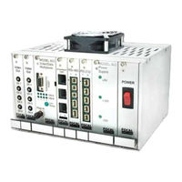
Moog Focal 903 User Manual (96 pages)
High Density (HD) Fiber Optic Video/Data Multiplexer
Brand:
Moog
| Category:
Multiplexer
| Size: 5 MB
Table of Contents
Table of Contents
3
1 Introduction
9
2 System Overview
10
Multiplexer Systems
10
Table 2-1: Model 903-HD Systems - Signal Types Supported
10
Figure 2-1: Model 903-HD Multiplexer - I/O Ports (4VID System)
11
Figure 2-2: Model 903-HD Multiplexer - I/O Ports (8VID System)
12
Rack Configuration
13
4VID Console and Remote Modules
13
Figure 2-3: Model 903-HD Mux Front Panel View - Card Configuration (4VID)
13
8VID Console and Remote Modules
14
Figure 2-4: Model 903-HD Mux Front Panel View - Card Configuration (8VID)
14
Channel Mapping
15
Figure 2-5: Console and Remote Modules (4VID) Showing Slot Pairings for Video and Data
15
Table 2-2: Typical Remote-To-Console Channel Mapping (4VID System)
16
Figure 2-6: Console and Remote Modules (8VID) Showing Slot Pairings for Video and Data
17
System Expansion
18
Table 2-3: Typical Remote-To-Console Channel Mapping (8VID System)
18
Optical Configuration
19
Figure 2-7: Model 903 Dual Fiber Optic Transmission System (4VID, 8VID)
19
Backwards Compatibility
20
3 Fiber Multiplexers and Backplanes
21
FMB-X-2.5 Fiber Multiplexer Board
21
Figure 3-1: Remote FMB-X-2.5 Front Panel View
21
Figure 3-2: Remote FMB-X-2.5 Plan View
22
Figure 3-3: Console FMB-X-2.5 Front Panel
23
Table 3-1: FMB-X-2.5 Front Panel Leds
23
Figure 3-4: FMB-X-2.5 RS-232 Diagnostic Cable: 1/8" (3.5 MM) Stereo to DB9F
24
Configuration Settings
25
Figure 3-5: Console FMB-X-2.5 Plan View
25
Remote FMB-X-2.5
25
Table 3-2: SW1 Configuration Settings
25
Table 3-3: SW2 Configuration Settings
25
Backplanes (-X Type) and Racks
26
Table 3-4: -X Backplanes Used in 4VID and 8VID Systems
26
Standard -X Backplanes
27
Figure 3-6: 28 HP -X Console Backplane (CBP-121-XC)
28
Figure 3-7: 44 HP -X Console Backplane (CBP-241-XC)
29
Figure 3-8: 12 HP High Density Remote Backplane PCBA (+24 VDC Input)
30
High Density -X Backplanes
30
Figure 3-9: 16 HP High Density Remote Backplane PCBA (+24 VDC Input)
31
Power Supply
32
Table 3-5: Typical Power Supplies for 903 Console and Remote Systems
32
Figure 3-10: Power Connectors Location (4VID and 8VID Systems)
33
4 Interface Cards
34
High Density Board (HDB-TX)
35
Video Channels
35
Figure 4-1: Remote High Density Board (HDB-TX) - Front Panel
35
Data Channels
36
Figure 4-2: HDB-TX PCB and Connector Location
37
Figure 4-3: HDB-TX Block Diagram
38
Data Input/Output Module (I/O-Box)
39
Figure 4-4: I/O Interface Box for 12 HP and 16 HP High Density Remote Systems
39
Table 4-1: AIB Plug-In Modules and I/O-Box Connector Pin Assignments (Typ 4VID and 8VID Systems)
40
Video Cards
41
VIB-X Video Board
41
Figure 4-5: VIB-X Front Panel
41
Figure 4-6: Block Diagram of VIB-X Card
42
Table 4-2: VIB-X Card Configuration Settings (Switch SW3)
43
Table 4-3: VIB-X Input/Output Video Format Configuration (Switch SW1)
43
Figure 4-7: VIB-X Plan View
44
Data Cards
45
AIB-4 - Adaptable Interface Board
45
Figure 4-8: Adaptable Interface Board (AIB-4) Front Panel
45
Figure 4-9: Adaptable Interface Board (AIB-4) PCB
46
Figure 4-10: Block Diagram of Adaptable Interface Board (AIB-4)
47
Plug-In Modules
48
RS-232 Plug-In (AIB-232/TRIGGER)
48
Table 4-4: AIB Plug-In Modules
48
Figure 4-11: AIB RS-232/TRIGGER Plug-In Module
49
Table 4-5: AIB-232 Pin Designations
49
RS-485/422/TTL Plug-In (AIB-485)
50
Figure 4-12: AIB RS-485 Plug-In Module
50
Figure 4-13: AIB RS-422 Interface Schematic
51
Table 4-6: AIB-485 Pin Designations
51
Table 4-7: Configuration Settings for AIB RS-485 Module (Defaults Shaded)
52
Tritech Sonar ARCNET Plug-In (AIB-ARCNET)
53
Figure 4-14: AIB Tritech ARCNET Plug-In Module
53
Table 4-8: Configuration Settings for AIB Tritech Module (Defaults Shaded)
53
Table 4-9: AIB-ARCNET Pin Designations
54
Hydrophone/Analog Plug-In (AIB-HYDRO)
55
Figure 4-15: AIB Hydrophone Plug-In Module
55
Table 4-10: Configuration Settings for AIB Hydrophone Module
55
Table 4-11: Hydrophone Gain Settings (Defaults Shaded)
55
Table 4-12: AIB-HYDRO Pin Designations
56
Figure 4-16: MS-900 Plug-In Module (Top View)
57
Table 4-13: AIB-MS900 Pin Designations
57
CANBUS Plug-In (AIB-CANBUS)
58
Figure 4-17: AIB-CANBUS Plug-In Module (Top View)
58
Table 4-14: CAN Speed Settings
59
Figure 4-18: WAGO 4-Pin Header
60
Table 4-15: AIB-CANBUS Pin Designations
60
5 Fiber Optics
61
Safety
61
System Design
61
Figure 5-1: Block Diagram of Model 903 Fiber Optic Transmission System
61
Table 5-1: Typical ROV System Power Budget
62
Fiber Handling Guidelines
63
Figure 5-2: LC Connector
64
Figure 5-3: ST Connector
64
Figure 5-4: SFP Transceiver
64
6 Installation and Operation
65
Mounting
65
Figure 6-1: Side View of Typical Model 903 Console Card Cage
65
Figure 6-2: Exploded View of a Model 903 4VID Console Card Cage
66
Figure 6-3: Side View of Typical 16 HP Model 903-HD Remote Card Cage
67
Cooling
68
Figure 6-4: Exploded View of a Model 903 High Density 4VID Remote Card Cage
68
Diagnostics
69
Bench Test for Model 903 Systems
70
Figure 6-5: Power Budget Test Setup - Transmit Optical Power Measurement
70
Figure 6-6: Power Budget Test Setup - Link Threshold Measurement
71
Figure 6-7: Power Budget Test Setup - Received Sensitivity Measurement
71
Maintenance
72
Model 903 Board Handling
73
7 Troubleshooting
74
System Verification
74
Initial Checks
74
Review Settings
74
Using Diagnostic Software
74
Most Common Problems
75
Most Common Video Problems
75
Most Common Data Problems
75
Most Common Optical Problems
75
Possible Problems, Symptoms, and Solutions
76
Diagnostic Leds
76
General Handling and Failure Reporting Guidelines
77
Focal Service and Support
77
Advertisement
Advertisement
Related Products
Moog FDW7CN-3 SERIES
Moog FusionDome FDW75C8N
Moog FCH11
Moog FCH11Q
Moog SView FDP7CN-3
Moog SView FDW7CS-3
Moog FusionDome FDW75F2N
Moog FusionDome FDW75CF2N
Moog FusionDome FDW75TF2N
Moog FusionDome FDW75CF2
Moog Categories
Synthesizer
Control Unit
Servo Drives
Medical Equipment
Security Camera
More Moog Manuals
Login
Sign In
OR
Sign in with Facebook
Sign in with Google
Upload manual
Upload from disk
Upload from URL