Sign In
Upload
Download
Table of Contents
Contents
Add to my manuals
Delete from my manuals
Share
URL of this page:
HTML Link:
Bookmark this page
Add
Manual will be automatically added to "My Manuals"
Print this page
×
Bookmark added
×
Added to my manuals
Manuals
Brands
ZOJE Manuals
Sewing Machine
ZJ5820
Operating manual
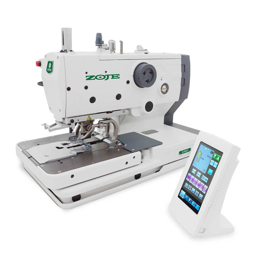
ZOJE ZJ5820 Operating Manual
Automatic eyelet buttonhole sewing machine
Hide thumbs
1
2
3
4
5
6
7
8
9
10
11
12
13
14
15
16
17
18
19
20
21
22
23
24
25
26
27
28
29
30
31
32
33
34
35
36
37
38
39
40
41
42
43
44
45
46
47
48
49
50
51
52
53
54
55
56
57
58
59
60
61
62
63
64
65
66
67
68
69
70
71
72
73
74
75
76
77
78
79
80
81
82
83
84
85
86
87
88
89
90
91
92
93
94
95
96
97
98
99
100
101
102
103
104
105
106
107
108
Table Of Contents
109
page
of
109
Go
/
109
Contents
Table of Contents
Bookmarks
Table of Contents
Safety Instructions
Safety Indications and Their Meanings
Indications
Symbols
Notes on Safety
Contents
Names of Major Parts
Safety Devices
Machine Specifications
Sewing Shapes
Installation
When Embedding into the Talle
Tilting Back and Returning the Machine Head
Returning the Machine Head to Its Original Position
To Return the Machine Head from the Second Step
To Return the Machine Head from the First Step
Installing the Belt Cover and Feed Bar Cover U
Installing the Air Unit and Valve Unit
Installing the 2-Pedal Foot Switch
Installing the Treadle Unit
Installing the Hand Start Switch
When Setting up on Top of the Table
Hand Start Switch Operation Method
Adjusting the Hand Start Switch Position
Forward/Back and Vertical Position
Forward/Back and Sideways Position
Lubrication
Adding Oil
Filling the Arm Oil Tank
Adding Oil to the Bed Oil Tank
Lubricating the Needle Bar
Oiling the Looper, Spreader and Looper Base
Preparation before Sewing
Installing the Needle
Threading the Gimp
Basic Operating Instruction
Operation Panel
Turn on Power
Step Pedal for Start
Basic Operation
Settting Methods of Patten Program
Interface for Inputting Sewing Data
Button Instruction Table
Setting of Pattern Program
About Hot Keys
List of Pattern Parameters at S Level
Confirm Pattern under Test Feed Mode
Step Presser Pedal
Step the Start Pedal
During the Cloth-Feeding
Last Stitch
Shift of Knife Actions
Non-Cut
Cut-Before-Sewing
Cut-After-Sewing
Method for Shifting Cloth Position
Threading Mode
Threading Upper Thread
Finish of Threading Upper Thread
Instructions on Sewing Operations
Auto Mode
Manual Mode
Pause Switch
At Last Stitch
Methods for Pausing
Method for Releasing Pause
Usage Instructions on Cyclical Sewing Function
Cyclical Pattern Program
Interface of Parameter Setting Mode
Description of Functions
Software Version Inquiry
Lightness Adjustment
Error Information Record
Communication Function
Operation Penal Update
Enter Software Update Interface
Finish Updating
Input/ Output U Level Parameters
Display the Communication Interface
When Inputting Patterns from U Disk
When Outputting Patterns from Operation
Parameter Setting
Method for Setting Parameters
Have Access to Parameter Setting Interface
Parameter Encryption
Change the Parameter
Check the Changed Parameter
List of Parameters at U Level
Initialization of Parameters
Parameter Back-Up & Recovery
Adjusting the Zigzag Base Line Position
Preparing a Short Customized Needle
Adjusting the Needle and Looper Timing
Adjusting the Clearance between the Loopers and Needle
Adjusting the Needle Guard
Adjusting the Spreader Installation Positions
Adjusting the Spreader Timing
Adjusting the Height of the Throat Plate
Changing the Cutting Length
Adjusting the Cutting Surface of the Hammer
Filing the Cutting Surface of the Hammer
Adjusting the Contact between the Knife and the Hammer
Contact Adjustment Method Using this Paper
Making Fine Adjustments to the Knife Position
Forward/Back Position Adjustment
Tilt Adjustment
Adjusting the Work Clamp Lift Amounts
Adjusting the Work Clamp Positions
Adjusting the Positions of the Work Clamp Plates
Adjusting the Cloth Opening Amounts
Adjusting the Upper Thread Feeding Amount
Cloth Opening Amount Adjustment
Adjusting the Upper Movable Knife
Adjusting the Position of the Thread Trimmer Lever Bracket
Replacing the Movable Knife and Fixed Knife
Movable Knife Replacement
Fixed Knife Replacement
Adjusting the Cutting Pressure
Adjusting the Meshing Amount
Adjusting the Thread Nipper Assembly and Opener
Adjusting the Thread Handler
Principle of the Thread Handler
Hint List
Malfunctions Settlement
Alarm Information List
Eyelet Buttonhole Machine System Diagram
Advertisement
Quick Links
1
Safety Instructions
2
Error Information Record
3
Alarm Information List
Download this manual
Table of
Contents
Previous
Page
Next
Page
1
2
3
4
5
Advertisement
Table of Contents
Need help?
Do you have a question about the ZJ5820 and is the answer not in the manual?
Ask a question
Questions and answers
Related Manuals for ZOJE ZJ5820
Sewing Machine ZOJE ZJ5780 Operation Manual
High-speed computer controlled lockstitch straight button-holing (30 pages)
Sewing Machine ZOJE ZJ5600N Instruction Manual
High-speed lockstitch sewing machine (56 pages)
Sewing Machine Zoje ZJ5600N Instruction Manual
High-speed lockstitch sewing machine (56 pages)
Sewing Machine ZOJE ZJ5821 Operating Manual
Automatic eyelet buttonhole sewing machine (109 pages)
Sewing Machine ZOJE ZJ5300 Instruction Manual
(25 pages)
Sewing Machine ZOJE ZJ5770A-1510HD Operation Manual
Computer-controlled pattern sewing machine with input function (32 pages)
Sewing Machine ZOJE ZJ9800 Operation Manual
High-speed lockstitch sewing machine (70 pages)
Sewing Machine ZOJE ZJ9800 Operation Manual
High-speed lockstitch sewing machine (69 pages)
Sewing Machine Zoje ZJ9600 Operation Manual
(53 pages)
Sewing Machine ZOJE ZJ8700 Instruction Manual
(42 pages)
Sewing Machine ZOJE ZJ757 Operation Manual
Super high-speed overlock sewing machine (53 pages)
Sewing Machine ZOJE ZJ781-BD Service Manual
(24 pages)
Sewing Machine ZOJE ZJ-M6-GS800-SF-V2 Operation Manual
Automatic mold (31 pages)
Sewing Machine ZOJE ZJ1900DSS-3-04-V4-TP Operation Manual
Computer-controlled high speed lockstitch bar tacking machine (32 pages)
Sewing Machine ZOJE ZJ20U Series Manual
Single needle lockstitch zig-zag sewing machine (6 pages)
Sewing Machine ZOJE ZJ9903 Operations Manual & Parts List
Straight needle for oil displacement micro machine (66 pages)
This manual is also suitable for:
Zj5821
Table of Contents
Save PDF
Print
Rename the bookmark
Delete bookmark?
Delete from my manuals?
Login
Sign In
OR
Sign in with Facebook
Sign in with Google
Upload manual
Upload from disk
Upload from URL


Need help?
Do you have a question about the ZJ5820 and is the answer not in the manual?
Questions and answers