Table of Contents
Advertisement
Quick Links
- 1 Installation
- 2 Operation of the Sewing Machine
- 3 6 ]Table of the Standard Patterns and Standard Clamp Foot
- 4 II.explanation of Computer-Controlled High-Speed Lockstitch Button Sewing Machine [ 1 ] Specifications
- 5 III.troubles and Corrective Measures (Sewing Conditions)
- 6 IV.drawing of the Table
- Download this manual
Advertisement
Table of Contents

Related Manuals for ZOJE ZJ1900DSS-3-04-V4-TP


Summary of Contents for ZOJE ZJ1900DSS-3-04-V4-TP
-
Page 2: Table Of Contents
COMPUTER-CONTROLLED HIGH SPEED LOCKSTITCH BAR TACKING MACHINE CONTENTS I. EXPLANATION OF COMPUTER-CONTROLLED HIGH-SPEED LOCKSTITCH BAR TACKING MACHINE SPECIFICATIONS ..........................1 CONFIGURSTION ..........................2 1. Names of main unit..........................2 INSTALLATION ..........................3 1. Attaching the connecting rod........................3 2. Installing the head support rod......................3 3. Installation of the sewing machine head....................4 4. - Page 3 COMPUTER-CONTROLLED HIGH SPEED LOCKSTITCH BAR TACKING MACHINE INSTALLATION OF THE SEWING MACHINE AND PREPARATION OF THE OPERATION ........................21 NEEDLE AND THREAD ........................21 POSITION OF THE BUTTON CLAMP ..................22 ADJUSTING THE FEED PLATE ....................23 ADJUSTING THE OPEN ANGLE OF THE BUTTON CLAMP JAW LEVER ....23 ADJUSTING THE LIFTING AMOUNT OF THE BUTTON CLAMP ......24...
-
Page 4: 1 ] Specifications
COMPUTER-CONTROLLED HIGH SPEED LOCKSTITCH BAR TACKING MACHINE EXPLANATION OF 1 SPECIFICATIONS 1. Sewing area X lateral direction 40mm Y longitudinal direction30mm 2. Max. Sewing speed 3200rpm (when sewing pitches are less than 5mm in X-direction and 3.5mm in Y-direction) 3. Stitch length 0.1-10mm (adjustable in 0.1mm step) 4. -
Page 5: Configurstion
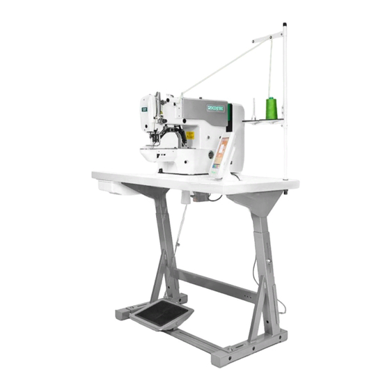
COMPUTER-CONTROLLED HIGH SPEED LOCKSTITCH BAR TACKING MACHINE 2 CONFIGURATION 1. Names of main unit . Work clamp feet . Machine head . Thread stand Power switch Operation panel Frame . Pedal switch - 2 -... -
Page 6: Installation
COMPUTER-CONTROLLED HIGH SPEED LOCKSTITCH BAR TACKING MACHINE 3 INSTALLATION 1. Attaching the connecting rod FIX connecting rod to installing hole B of pedal lever with nut . When connecting rod is installed in installing hole A, the depressing stroke go the pedal is increased. -
Page 7: Installation Of The Sewing Machine Head
COMPUTER-CONTROLLED HIGH SPEED LOCKSTITCH BAR TACKING MACHINE 3. Installation of the swing machine head To prevent possible accidents caused by the full of the sewing machine, perform the work by two persons or more when the machine is (1).The oil plate with wood screws fixed in the corresponding position of the platen. -
Page 8: Installing The Drain Receiver
COMPUTER-CONTROLLED HIGH SPEED LOCKSTITCH BAR TACKING MACHINE 4. Installing the drain receiver Fix drain receiver in the installing hole of table with four setscrews . Screw in drain bin to drain receiver . Insert sewing machine drain pipe into drain bin Insert drain pipe until it will go on further so that it does not... -
Page 9: Connecting The Operation Panel
COMPUTER-CONTROLLED HIGH SPEED LOCKSTITCH BAR TACKING MACHINE Connecting the opera t ion panel Please let the operation panel line connect with the electronic control box according to online identity, make sure the connection is correct. . Installing the eye protection cover Be sure to attach this cover to protect the eyes from the disperse of needle breakage. -
Page 10: Installing The Thread Stand
COMPUTER-CONTROLLED HIGH SPEED LOCKSTITCH BAR TACKING MACHINE 8. Installing the thread stand The line frame in the accessory box should be installed in Table. 4 OPERATION OF THE SEWING MACHINE 1. Lubrication Turn of the power before starting the work so as to prevent accidents caused by abrupt start of the sewing machine Check that the place between lower line Band upper line A is filled with oil . -
Page 11: Attaching The Needle
COMPUTER-CONTROLLED HIGH SPEED LOCKSTITCH BAR TACKING MACHINE 2. Attaching the needle Turn of the power before starting the work so as to prevent accidents caused by abrupt start of the sewing machine Loosen setscrew and hold needle with the long groove facing toward you. Then fully insert it into the hole in the needle bar, and tighten setscrew . -
Page 12: Installing And Removing The Bobbin Case
COMPUTER-CONTROLLED HIGH SPEED LOCKSTITCH BAR TACKING MACHINE .Installing and removing the bobbin case Turn of the power before starting the work so as to prevent accidents caused by abrupt start of the sewing machine. .Open hook cover .Raise latch of bobbin case remove the bobbin case. -
Page 13: Adjusting The Thread Tension
COMPUTER-CONTROLLED HIGH SPEED LOCKSTITCH BAR TACKING MACHINE 6. Adjusting the thread tension If thread tension controller No.1 is turn clockwise, the length of remaining thread on the needle after thread trimming will be shorter. If it turned counterclockwise, the length will be longer. -
Page 14: Maintenance
COMPUTER-CONTROLLED HIGH SPEED LOCKSTITCH BAR TACKING MACHINE MAINTENANCE 1. Adjusting the height of the needle bar Turn OFF the power before starting the work so as to prevent accidents cause by abrupt start of the sewing machine. F type only Bring needle bar to the lowest position of its stroke. -
Page 15: Adjusting The Lift Of The Work Clamp Foot
COMPUTER-CONTROLLED HIGH SPEED LOCKSTITCH BAR TACKING MACHINE Loosen setscrew in the driver. Open inner hook pressers to the right and left, and remove inner hook presser At this time, be careful not to let inner hook come off and fall. Adjust so that the blade point of inner hook aligns with the center of needle... -
Page 16: The Moving Knife And Counter Knife
COMPUTER-CONTROLLED HIGH SPEED LOCKSTITCH BAR TACKING MACHINE Turn OFF the power before starting the work so as to prevent accidents cause by abrupt start of the sewing machine. (1) With the machine in stop mode, remove two set screws of the right decorative panel ,then remove the decorative panel along the K direction. -
Page 17: Adjusting The Wiper
COMPUTER-CONTROLLED HIGH SPEED LOCKSTITCH BAR TACKING MACHINE 5. Adjusting the wipper Loosen screw to adjust so that a clearance of1.5 mm or more is provided between the wiper and the needle. At this time, the standard of the distance between the wiper and the needle is 23 to 25 mm. -
Page 18: Replenishing The Designed Places With Grease
COMPUTER-CONTROLLED HIGH SPEED LOCKSTITCH BAR TACKING MACHINE 8.Replenishing the designated places with grease When the sewing machine has been used for a certain number of times of sewing, error code No. E221 is displayed on the operation panel at the time of turning ON the power. This display informs the operator of the time of replenishing the designated places with oil. -
Page 19: Adjusting The Position Of The Shear Driv Pulley
COMPUTER-CONTROLLED HIGH SPEED LOCKSTITCH BAR TACKING MACHINE positioning groove Keep the left end of the pulley aligned with the right end of the positioning groove that in the shear-driving shaft Then tighten the screw on the pulley. reference plane... - Page 20 COMPUTER-CONTROLLED HIGH SPEED LOCKSTITCH BAR TACKING MACHINE Rotate the lift motor shaft to turn the lift cam to the lowest point of contact with the lift roller,this moment the sc ew is facing directly above Positioning reference plane of the trimming safety sensor chip horizontally upwards,and placing the trimming safety sensor chip in the trimming safety sensor, then locking the screw to fix the trimming safety sensor.
-
Page 21: 6 ]Table Of The Standard Patterns And Standard Clamp Foot
COMPUTER-CONTROLLED HIGH SPEED LOCKSTITCH BAR TACKING MACHINE . Table of the clamp foot Left 10011508 Right 10011505 10011687 10011691 10011758 10011759 Work clamp foot 10011565 10012300 10012279 10011751 10011755 With knurl Without knurl Without knurl With knurl With knurl Feed plate Sewing specification Finer guard... - Page 22 COMPUTER-CONTROLLED HIGH SPEED LOCKSTITCH BAR TACKING MACHINE 10026247(L) 10026250(L) 10012344(L) 10026253(L) 10026256(L) 10026248(R) 10026251(R) 10012345(R) 10026254(R) 10026257(R) Work clamp foot 10026249 10026252 10012338 10026255 10026258 Without knurl Without knurl Without knurl Without knurl Without knurl Feed plate Sewing specification 10011556 guard Remarks Optional...
-
Page 23: Table Of The Optional Parts
COMPUTER-CONTROLLED HIGH SPEED LOCKSTITCH BAR TACKING MACHINE Table of the optional parts Name of Parts Type Part No. Remarks Feed plate blank With knurl / processed t=1.2 10012303 Sewing area lengthwise 20 X crosswise 40 With knurl / processed 10014401 Sewing area lengthwise 30 X crosswise 40 Needle hole guide 10047532... -
Page 24: Ii.explanation Of Computer-Controlled High-Speed Lockstitch Button Sewing Machine [ 1 ] Specifications
COMPUTER-CONTROLLED HIGH SPEED LOCKSTITCH BAR TACKING MACHINE .EXPLANATION OF THE COMPUTER-CONTROLLED HIGH SPEED LOCKSTITCH BUTTON SEWING MACHINE 1 Specifications Different specifications from those of the bartacking machine only are described. 1) Sewing speed ..........Max. 2700rpm 2) Needle ............DPx17 #14 3) Lifting method of the work clamp foot.. -
Page 25: Position Of The Button Clamp
COMPUTER-CONTROLLED HIGH SPEED LOCKSTITCH BAR TACKING MACHINE 4 Position of the button clamp jaw lever 1).Place a button in button clamp jaw levers 2). With sewing LED goes off ,press key in the operation panel,then press key to make machine find the zero position. -
Page 26: Adjusting The Feed Plate
COMPUTER-CONTROLLED HIGH SPEED LOCKSTITCH BAR TACKING MACHINE 5 Adjusting the feed plate WARNING: When change of the shape of the button, change of the sewing pattern or enlargement/reduction of the sewing width is performed, make sure of the shape of the sewing pattern. If the feed plate interferes with the needle hole guide, it will result in the danger of the needle breakage or the like. -
Page 27: Adjusting The Lifting Amount Of The Button Clamp
COMPUTER-CONTROLLED HIGH SPEED LOCKSTITCH BAR TACKING MACHINE Adjusting the lifting amount of the button clamp Turn OFF the power before starting the work so as to prevent accidents cause by abrupt start of the sewing machine. Loosen two setscrews ,and move moving plate back and forth in the direction of arrow to adjust. -
Page 28: 9 ] Adjusting The Wiper Sping
COMPUTER-CONTROLLED HIGH SPEED LOCKSTITCH BAR TACKING MACHINE Adjust the wiper spring Turn OFF the power before starting the work so as to prevent accidents cause by abrupt start of the sewing machine. Wiper spring retains the needle thread after thread trimming in between wiper and the wiper spring. -
Page 29: Iii.troubles And Corrective Measures (Sewing Conditions)
COMPUTER-CONTROLLED HIGH SPEED LOCKSTITCH BAR TACKING MACHINE Trouble Cause Corrective measures Adjust the clearance between the needle and the Stitches are slipped at the shuttle to 0.05 to 0.1mm. start Set soft-start sewing at the start of bar tacking. needle thread Correct the thread tension release timing of the remaining on the needle... - Page 30 COMPUTER-CONTROLLED HIGH SPEED LOCKSTITCH BAR TACKING MACHINE Needle thread is stepped wiper.(23 to 25mm) on by the work clamp foot at the start of sewing (Needle bend) The counter knife is dull. The difference in level between the needle hole Replace the counter knife.
- Page 31 COMPUTER-CONTROLLED HIGH SPEED LOCKSTITCH BAR TACKING MACHINE Trouble Cause Corrective measures 7.Threads break at The moving knife has time of been improperly Correct the position of the moving knife. thread position trimming 8.Uneven length of The tension of thread Increase the tension of the thread take-up spring. the needle take-up spring is too low.
-
Page 32: Iv.drawing Of The Table
COMPUTER-CONTROLLED HIGH SPEED LOCKSTITCH BAR TACKING MACHINE .DRAWING OF THE TABLE...
Need help?
Do you have a question about the ZJ1900DSS-3-04-V4-TP and is the answer not in the manual?
Questions and answers