Table of Contents
Advertisement
e
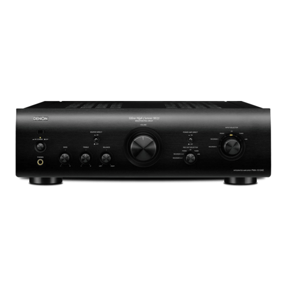
PMA-1510AE
•
• Please use this service manual with referring to the operating instructions without fail.
• Some illustrations using in this service manual are slightly different from the actual set.
SERVICE MANUAL
MODEL
INTEGRATED AMPLIFIER
JP
E3
E2
e
D&M Holdings Inc.
Ver. 5
Please refer to the
MODIFICATION NOTICE.
EK
K2A
E1
E1K EUT
Advertisement
Table of Contents

Related Manuals for Denon PMA1510AE


Summary of Contents for Denon PMA1510AE
-
Page 1: Service Manual
Ver. 5 Please refer to the MODIFICATION NOTICE. SERVICE MANUAL MODEL E1K EUT PMA-1510AE INTEGRATED AMPLIFIER • • Please use this service manual with referring to the operating instructions without fail. • Some illustrations using in this service manual are slightly different from the actual set. D&M Holdings Inc. -
Page 2: Safety Precautions
SAFETY PRECAUTIONS The following check should be performed for the continued protection of the customer and service technician. LEAKAGE CURRENT CHECK Before returning the unit to the customer, make sure you make either (1) a leakage current check or (2) a line to chassis resistance check. -
Page 3: Note For Schematic Diagram
NOTE FOR SCHEMATIC DIAGRAM WARNING: Parts marked with this symbol z have critical characteristics. Use ONLY replacement parts recommended by the manufacture CAUTION: Before returning the unit to the customer, make sure you make either (1) a leakage current check or (2) a line to chassis resistance check. If the leakage current exceeds 0.5 milliamps, or if the resistance from chassis to either side of the power cord is less than 460 kohms, the unit is defective. -
Page 4: Technical Specifications
TECHNICAL SPECIFICATIONS Rated Output Power : SN Ratio (A network) : 2-channel driving (CD → SP OUT) PHONO (MM): 89 dB (With input terminals short-circuited, 5 mV input signal) 70 W + 70 W (8 Ω, 20 Hz ~ 20 kHz, T.H.D. 0.07 %) PHONO (MC): 74 dB Dynamic power : (With input terminals short-circuited, 0.5 mV input signal) - Page 5 DISASSEMBLY TOP COVER FRONT PANEL ASSY INPUT UNIT BACK PANEL "DISASSEMBLY "DISASSEMBLY "DISASSEMBLY 1.FRONT PANEL ASSY" 3. INPUT UNIT" 6. BACK PANEL" "EXPLODED VIEW" "EXPLODED VIEW" "EXPLODED VIEW" U-COM UNIT TRANS "DISASSEMBLY "DISASSEMBLY 4. U-COM UNIT" 7. TRANS" "EXPLODED VIEW" "EXPLODED VIEW"...
-
Page 6: Front Panel Assy
About the photos used for descriptions in the DISASSEMBLY" section. The viewpoint of each photograph Direction of photograph: B (Photografy direction) Front side [View from above] Direction of Direction of photograph: C photograph: D Direction of photograph: A 1. FRONT PANEL ASSY Proceeding : TOP COVER FRONT PANEL ASSY... - Page 7 CY038 CX151, CX082 CY035 CY052 CX061 CX065 < Attention of assembling >...
-
Page 8: Radiator Assy
2. POWER AMP UNIT Proceeding : TOP COVER FRONT PANEL ASSY POWER AMP UNIT → → CX023 CX024 CX033 CY091 CX052 RADIATOR ASSY... -
Page 9: Input Unit
Solder View from bottom RADIATOR ASSY 3. INPUT UNIT Proceeding : TOP COVER INPUT UNIT → Direction of photograph: A CX081 CX102 CX072 CY035 CX061 P.W.B. HOLDER Direction of photograph: D... - Page 10 4. U-COM UNIT Proceeding : TOP COVER INPUT UNIT U-COM UNIT → → P.W.B HOLDER CY102 CY031 CY051 CY091 Direction of photograph: C P.W.B HOLDER CY032 5. REC INPUT UNIT Proceeding : TOP COVER U-COM UNIT REC INPUT UNIT → →...
-
Page 11: Back Panel
6. BACK PANEL Proceeding : TOP COVER BACK PANEL → CX047 INPUT UNIT Direction of photograph: A 7. TRANS Proceeding : TOP COVER TRANS → CX023 CX024 CY031, CY032 CX022 CORD HOLDER : Loose CX021... -
Page 12: Idling Adjustment
IDLING ADJUSTMENT DC Voltmeter Trans TP801 TP802 VR801 VR802 Trans 8U-110081-1 Power Amp P.W.B. Volume IDLING CURRENT → → →... -
Page 13: Troubleshooting
TROUBLE SHOOTING 1. The power can not be turned on. (Power indication LED does not light.) Check the insertion of the 8U-110081-2 AC UNIT . Check the insertion of the Check whether power is Power not supplied. being supplied to the coil Broken wire in standby (T101). - Page 14 Personal notes:...
-
Page 15: Block Diagram And Level Diagram
BLOCK DIAGRAM AND LEVEL DIAGRAM BROCK DIAGRAM LEVEL DIAGRAM... -
Page 16: Power Supply Block Diagram
POWER SUPPLY BLOCK DIAGRAM... -
Page 17: Printed Wiring Boards
PRINTED WIRING BOARDS 8U-110081-1 (COMPONENT SIDE) TR815 JV38 C809 C807 TR823 22.5 JV995 JV994 C835 22.5 PH902 JV93 C813 R865 JV993 JV992 TR825 20.0 JV27 JV26 12.5 20.0 TR821 JV46 12.5 D803 JV78 17.5 TR819 JV88 JV104 TP801 R857 17.5 JV30 TR827 R851... - Page 18 8U-110081-4 (COMPONENT SIDE) 8U-110081-5 (COMPONENT SIDE) 8U-110081-6 (COMPONENT SIDE) 8U-110081-7 (COMPONENT SIDE) CY062 CX063 C603 C604 8U-110081-5 R602 CX064 JV110 VOLUME UNIT CY063 JV99 12.5 C605 JV32 S601 12.5 20.0 W601 JV76 IC501 JV28 JV11 JV89 P.LED UNIT JV114 12.5 8U-110081-6 CY061 JV43...
- Page 19 8U-210024-1 (COMPONENT SIDE) C313 ZD301 JV114 ZD302 8U-110082-1 JV199 JV197 u-com UNIT C340 C330 ZD303 JV182 C307 C301 C338 JV171 JV61 C331 JV181 JV27 22.5 C302 C314 C311 JV189 15.0 JV185 JV24 JV192 JV38 25.0 JV118 C332 12.5 C333 C305 JV77 JV172 25.0...
- Page 20 8U-210024-2 (COMPONENT SIDE) 8U-210024-3 (COMPONENT SIDE) J402 R402 R404 R441 JV36 JV67 ST501 S401 R438 C428 L402 L404 R442 R432 JV51 JV46 C235 JV91 JV47 JV50 L401 L403 JV48 R431 IC401 R437 S503 J401 R401 R403 D203 C236 LD506 C219 CX102 C230 R224...
- Page 21 8U-210024-4 (COMPONENT SIDE) 8U-210024-4 (FOIL SIDE) 8U-210024-5 (COMPONENT SIDE) 8U-210024-5 (FOIL SIDE) R726 8U-110082-4 R.SEL.SW.UNIT C720 JV16 D514 17.5 C719 R527 R528 R725 JV117 S502 JV107 ST701 JV108 17.5 C722 R529 C721 JV60 15.0 R728 R531 R727 R532 C718 R533 C717 R730 R534...
-
Page 22: Schematic Diagrams
8U-110081-1 TP801 3P-NH JV993 JV992 BUSBAR BUSBAR POWER AMP UNIT 8U-110081-4 JV995 JV994 BUSBAR BUSBAR FRONT SW UNIT JV997 JV996 W602 W603 BUSBAR BUSBAR R889 M3-SIDE R857 M3-SIDE 100(1W) HOLE TYPE HOLE TYPE JV999 JV998 R869 SOURCE DIRECT 2.2K BUSBAR BUSBAR C805 8U-110081-5... - Page 23 8U-110082-2 To VOL UNIT INPUT UNIT IC401 BA4558 C423 10/50 TR401,403 (1/2) 2SK369 C419 R415 C413 R401 R403 1200P W403 OPEN 3300P C411 CW101 8U-110082-5 100P 10P-SCN R409 C417 C421 J403 0.068 0.018 TR403 TONE UNIT L401 SHORT L403 2SK369 R441 R423 R425...
- Page 24 ST501 8U-110082-3 STYLE-PIN FUNCTION SW 50mm UNIT CY151 15P-KRs R520 R521 OPEN OPEN R522 R523 D_GND PH-LED CD-LED TUNER-LED LINE-LED RECORDER-1-LED R501 R503 R504 R505 R506 R507 R508 R509 R510 R511 R512 R513 R514 R515 R516 R518 R525 RECORDER-2-LED 120K 4.7K 1.5K 3.9K...
-
Page 25: Wiring Diagram
WIRING DIAGRAM... -
Page 26: Exploded View
EXPLODED VIEW : E2 ONLY 152 162 153 163 1-10 151 161 154 164 Back view WARNING: Parts marked with this symbol have critical characteristics. Use ONLY replacement parts recommended by the manufacturer. -
Page 27: Parts List Of Exploded View
PARTS LIST OF EXPLODED VIEW Ref. No. Part No. Part Name Remarks Q'ty 00D2750105004 2SK2967 TR821, TR822, TR824, TR824 zParts for which "nsp" is indicated on this table cannot be supplied. zP.W.B. ASS'Y for which "nsp" is indicated on this table cannot be supplied. When repairing the P.W.B. ASS'Y, check the board parts table and order replacement parts. INSULATING SHEET zThe parts listed below are for maintenance only, might differ from the parts used in the unit in appearances or dimensions. - Page 28 ★ ★ ★ ★ ★ ★ ★ ★ ★ ★ ★ ★ ★ ★ ★ ★ ★ ★ ★ ★ ★ ★ ★ ★ ★ ★ ★ ★ ★ ★ ★ ★...
-
Page 29: Packing View
PACKING VIEW 201 203 204 205 206 201 202 PARTS LIST OF PACKING & ACCESSORIES zParts for which "nsp" is indicated on this table cannot be supplied. zThe parts listed below are for maintenance only, might differ from the parts used in the unit in appearances or dimensions. Note: The symbols in the column "Remarks"... - Page 30 SEMICONDUCTORS Only major semiconductors are shown, general semiconductors etc. are omitted to list. The semiconductor which described a detailed drawing in a schematic diagram are omitted to list. 1. IC's TMP86FH47AUG (8U-110082 : IC301) VAREF P13( AVDD P14( AVSS P15(INT3) P07(INT4) P06( P05(SI)
- Page 31 R5F64169DFD Terminal Functions port function active normal to GND x'tal XOUT x'tal TEST to VSS/VDD to 3.3v P21(XTIN) LED R P22(XTOUT) LED G REST reset P20(STOP/INT5) Stop mode cancellation HIGH eddge P00(INT0) ASO/DC protector LOW eddge P01(TC4) P direct output P02(RXD) RXD(prom) P03(TXD)
- Page 32 TC9163AN (8U-110082 : IC201) TC9164AN (8U-110082 : IC202) TC74HC123AF (8U-110082 : IC306)
- Page 38 Ref. No. Part No. Part Name Remarks Q'ty ZD302 00D2760634905 MTZJ3.3AT77 LD502-507 00D3939658915 SEL2915A-TP6 RESISTORS GROUP R217,218 RD14B2E334JT(AMRS) R223,224 RD14B2E221JT(AMRS) R441,442 00D2412375907 RD14B2E100JNBST R731,732 00D2442051974 RS14B3A102JNBST(S) VR701 00D2110798103 V14V20FW104K VR702 00D2110834012 V14V20FA103K VR703 00D2110834009 V14V20FA303K CAPACITORS GROUP C215,216 00D2544702956 CE04W1H100MT(RFS#A) C217-219 CE04W1H100MT(RA3) C221,222...
- Page 39 Ref. No. Part No. Part Name Remarks Q'ty C332 CE04W1C331MT(RA3) C333 CE04W1H010MT(RA3) C334 CE04W1H330MT(RA3) C335 CQ93M2A104JT(PEF) C336 CQ93M2A103JT(PEF) C337,338 CE04W1C332MC(RA3) C339,340 CE04W1H100MT(RA3) C341 CQ93M2A104JT(PEF) C405,406 CQ93P2D470K(FAS) C407,408 CQ93M2E151J(LP) C409,410 CQ93M2A102JT(PEF) C411,412 CQ93M2E101J(LP) C413,414 CQ93M2A332JT(PEF) C415,416 CE04W1H101MT(RA3) C417,418 CQ93P2A683JT(PPF) C419,420 CQ93M2A122JT(PEF) C421,422 CQ93M2A183JT(PEF) C423,424...
- Page 40 Ref. No. Part No. Part Name Remarks Q'ty CY064 6P KR CON BASE(L) CY102 10P CON.BASE(KR-PH) CY151 15P KR CON BASE(L) z F301,302 00D2061031045 FUSE (0.25)A FF301,302 FUSE CLIP(TAPE) FH301,302 FUSE CLIP(TAPE) J401,402 VINYL WIRE JK201,202 643010048000S 4P PIN JACK(MSP-244V4)-AU JK601 643010048000S 4P PIN JACK(MSP-244V4)-AU...
Need help?
Do you have a question about the PMA1510AE and is the answer not in the manual?
Questions and answers