
Subscribe to Our Youtube Channel
Related Manuals for Pumpex K 101


Summary of Contents for Pumpex K 101
- Page 1 Service instruction K 101, K 151, K 200, K 250, K 300 (M50 Motors) K 101/151/200/250/300.58.0404.Eng/Digital...
-
Page 2: Table Of Contents
SERVICE INSTRUCTION K 101, 151, 200, 250, 300 K 101/151/200/250/300.58.0404.Eng/Digital Table of Contents Introduction..........................3 Cross-sectional drawing......................4 Nameplate........................4 Safety Precautions........................4 Minimizing Environmental Impact..................5 General Maintenance......................5 Disassembling Removal from the Wet Well....................6 Disassembling the Volute.....................6 Adding and Changing the Oil....................6 Changing the Cooling Liquid....................7... -
Page 3: Introduction
SERVICE INSTRUCTION K 101, 151, 200, 250, 300 K 101/151/200/250/300.58.0404.Eng/Digital This service manual covers pumps K 101, K 151, K 200, K 250 and K 300 with M50 motors in the following designs: Type F Wet Pit Installation Installed on a guide rail system with a quick- release base elbow, the base elbow is bolted to the floor of the sump. -
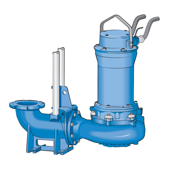
Page 4: Cross-Sectional Drawing
SERVICE INSTRUCTION K 101, 151, 200, 250, 300 K 101/151/200/250/300.58.0404.Eng/Digital SmartSeal Seal Cartridge Cable Seal EcoCool Internal Closed Loop Cooling System Stator Unit Guide Rails Discharge Elbow Rotor Volute ○ ○ ○ Impeller Optimizer Adjustable Wear Ring Notice! Standard nameplate... -
Page 5: Minimizing Environmental Impact
SERVICE INSTRUCTION K 101, 151, 200, 250, 300 K 101/151/200/250/300.58.0404.Eng/Digital Minimizing the Environmental Impact A life cycle analysis shows that the larger part of the environmental impact caused by pumps arises in the operating phase. In the five categories of environmental impact, the operating phase constitutes the major part. -
Page 6: Disassembling
(Fig. 1-2) QuickLock Latch Bolts Adding and Changing the Oil The oil housing of PUMPEX wet pit pumps is filled with oil at the plant. Type of Oil: White Oil (e.g. Enerpar M002 or Similar). Oil Amount: 4 dl (0.9 US pints) -
Page 7: Changing The Cooling Liquid
SERVICE INSTRUCTION K 101, 151, 200, 250, 300 K 101/151/200/250/300.58.0404.Eng/Digital Changing the Cooling Liquid First disassemble the motor unit from the volute. Pump Without Cooling Jacket: Loosen the cooling liquid plug down on the cooling plate. Open the plugs on top of the oil housing and let the old water pour out. -
Page 8: Disassembling The Terminal Housing
SERVICE INSTRUCTION K 101, 151, 200, 250, 300 K 101/151/200/250/300.58.0404.Eng/Digital Disassembling the Terminal Housing Disassemble cover as instructed above. Remove the six screws that hold the terminal housing in place. Loosen the cables coming out of the motor unit from the terminal block. -
Page 9: Disassembling The Stator
If the stator still cannot be used, it has to be replaced. Disconnect the stator from the outgoing cables and disassemble it. Order an exchange stator unit from the nearest Pumpex Service Center. Disassembling the Stator Disassemble the terminal housing as instructed above. -
Page 10: Disassembling The Rotor And Bearings
SERVICE INSTRUCTION K 101, 151, 200, 250, 300 K 101/151/200/250/300.58.0404.Eng/Digital Disassembling the Rotor and Ball Bearings The rotor is mounted in the motor unit with an upper and two lower bearings. Install the eyebolt (M16) into the drilled hole in the shaft (Fig.7). -
Page 11: Mounting The Rotor In The Oil Housing
SERVICE INSTRUCTION K 101, 151, 200, 250, 300 K 101/151/200/250/300.58.0404.Eng/Digital Mounting the Rotor in the Oil Housing Heat the oil housing before mounting the rotor (Fig. 9). Lift the rotor carefully in place with help of an eyebolt (Fig.10). Mounting the Stator Push the stator in with the pressure tool (Fig. -
Page 12: Mounting The Impeller
SERVICE INSTRUCTION K 101, 151, 200, 250, 300 K 101/151/200/250/300.58.0404.Eng/Digital Mounting the Impeller Turn the shaft so that the key slot is upward. Put the key in its groove and push the impeller onto the shaft. Lock the impeller to prevent it from rotating with a pipe or similar tool and fasten the impeller washer and screw (Fig.12). -
Page 13: Mounting The Motor Unit To The Volute
SERVICE INSTRUCTION K 101, 151, 200, 250, 300 K 101/151/200/250/300.58.0404.Eng/Digital Mounting the Motor Unit to the Volute Turn the latch bolts so that the motor unit runs free down to the upper edge of the volute. Turn the latch bolts in and fasten the screws alternately. -
Page 14: Wiring Diagram
SERVICE INSTRUCTION K 101, 151, 200, 250, 300 K 101/151/200/250/300.58.0404.Eng/Digital Wiring Diagram Ä Direct on-line starting Direct on-line starting Y/Ä Star/Delta starting 14 (15) -
Page 15: Torque Rating
SERVICE INSTRUCTION K 101, 151, 200, 250, 300 K 101/151/200/250/300.58.0404.Eng/Digital Torque Rating Size [Nm] [lb-ft] 12.5 24.3 42.0 67.1 103.3 Size [Nm] [lb-ft] Impeller Bolt (M16 Bumax) Latch Bolt (M16 A4-80) Cable Gland: A specific torque value cannot be given for the cable gland. Tighten it until the rubber offers resistance, and thereafter, one more full rotation.
Need help?
Do you have a question about the K 101 and is the answer not in the manual?
Questions and answers