Table of Contents
Advertisement
Available languages
Available languages
Item #1000 022 652, 1000 019 369
Model #42010, 99913
UL Model #52-SKV
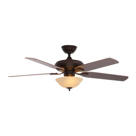
USE AND CARE GUIDE
FLOWE 52 IN. CEILING FAN
Questions, problems, missing parts? Before returning to the store call
Hampton Bay Customer Service
8 a.m. - 6 p.m., EST, Monday-Friday
1-855-HD-HAMPTON
HAMPTONBAY.COM
THANK YOU
We appreciate the trust and confidence you have placed in Hampton Bay through the purchase of this ceiling fan. We strive to continually create
quality products designed to enhance your home. Visit us online to see our full line of products available for your home improvement needs.
Thank you for choosing Hampton Bay!
Advertisement
Chapters
Table of Contents

Related Manuals for HAMPTON BAY 42010


Summary of Contents for HAMPTON BAY 42010
- Page 1 THANK YOU We appreciate the trust and confidence you have placed in Hampton Bay through the purchase of this ceiling fan. We strive to continually create quality products designed to enhance your home. Visit us online to see our full line of products available for your home improvement needs.
-
Page 2: Table Of Contents
Table of Contents Table of Contents ..............2 Assembly................7 Safety Information ............... 2 Operation ................17 Warranty ................3 Care and Cleaning ............. 18 Pre-Installation ..............3 Troubleshooting..............18 Installation................6 Safety Information To reduce the risk of electric shock, ensure the electricity has WARNING: To reduce the risk of personal injury, do been turned off at the circuit breaker or fuse box before you not bend the blade brackets (also referred to as... -
Page 3: Warranty
A certain amount of “wobble” is normal and should not be considered a defect. Servicing performed by unauthorized persons shall render the warranty invalid. There is no other express warranty. Hampton Bay hereby disclaims any and all warranties, including but not limited to those of merchantability and fitness for a particular purpose to the extent permitted by law. - Page 4 Pre-Installation (continued) HARDWARE INCLUDED NOTE: Hardware not shown to actual size. Part Description Quantity Part Description Quantity Plastic wire connector Extra lock washer Hanger pin Rubber gasket Locking pin Plastic plug Extra blade bracket screw...
- Page 5 Pre-Installation (continued) PACKAGE CONTENTS Part Description Quantity Part Description Quantity Slide-on mounting bracket Light kit fitter assembly (inside canopy) Blade Ball/downrod assembly Blade bracket Canopy with canopy ring attached Glass bowl Decorative motor collar cover Remote control (battery included) Fan-motor assembly Receiver CFL Light bulb, 14-Watt maximum IMPORTANT: This product and/or components are...
-
Page 6: Installation
Installation MOUNTING OPTIONS WARNING: To reduce the risk of fire, electric shock or personal NOTE: You may need a longer downrod to maintain proper injury, mount to an outlet box marked “Acceptable for fan blade clearance when installing on a steep, sloped ceiling. The support of 35 lbs. -
Page 7: Assembly
Assembly - Standard Ceiling Mount Preparing for mounting Routing the wires Remove the canopy ring (M) from the canopy (C) by turning Route the wires exiting the top of the fan motor the ring counter-clockwise until it unlocks. assembly (E) through the center of the canopy ring (M). Make sure the slots on the canopy ring (M) are on top. - Page 8 Assembly - Close-To-Ceiling Mount Preparing for mounting Routing the wires Remove canopy ring (M) from the canopy (C) by turning the Remove three of the six screws and lock washers (PP) ring counter-clockwise until it unlocks. (every other one) securing the motor collar to the top of the fan-motor assembly (E).
- Page 9 Assembly - Hanging the Fan Attaching the mounting bracket to Hanging the fan the outlet box WARNING: To reduce the risk of fire, electric shock WARNING: The hook (XX) is only to balance the fan while or personal injury, mount to an outlet box marked making the electrical connections.
- Page 10 Assembly - Hanging the Fan (continued) Setting the code on the remote Installing the receiver control and receiver NOTE: The frequencies on your receiver and remote WARNING: To reduce the risk of fire or electric shock, control have been preset at the factory. Before installing remember to disconnect power.
- Page 11 Assembly - Hanging the Fan (continued) Wiring the receiver to the household wiring WARNING: To avoid possible electrical shock, turn the electricity off at the main fuse box before wiring. If you feel you do not have enough electrical wiring knowledge or experience, contact a licensed electrician.
- Page 12 Assembly - Hanging the Fan (continued) Wiring the fan to the receiver Outlet box in the ceiling (MM) WARNING: Remove the rubber motor stops on the bottom of the fan before installing the blades or testing the motor. Green IMPORTANT: Use the wire connecting nuts (AA) supplied with your fan.
- Page 13 Assembly - Hanging the Fan (continued) Wrapping the extra wire Mounting the fan-motor assembly (standard mount) WARNING: When using the standard ball/downrod mounting, the NOTE: Follow this step ONLY if you did not cut the extra length off tab in the ring at the bottom of the mounting bracket must rest in from the wires coming from the ceiling fan to the receiver.
- Page 14 Assembly - Hanging the Fan (continued) Mounting the fan-motor assembly (close-to-ceiling mount) WARNING: The locking slots of ceiling canopy are provided only as an aid to mounting. Do not leave the fan assembly unattended until all four canopy screws are engaged and firmly tightened. Carefully unhook the fan from the mounting bracket (A) and align the locking slots of the ceiling canopy (C) with the two screws in the mounting bracket (A).
- Page 15 Assembly - Attaching the Fan Blades Attaching the blades Mount the fan blades (G) to the blade bracket (H) by aligning the three key-slot holes in the blade (G) with the three posts on the top of the blade brackets (H). Hold the blade (G) with both hands close to the blade bracket (H) and press the blade (G) down firmly.
- Page 16 Assembly - Attaching the Lights Installing the bulbs and attaching the glass bowl CAUTION: Do not over tighten the hex nut, overtightening the hex nut may cause the glass to break. Remove the rubber washer (P), hex nut (Q), bottom cover (R), and finial nut (S) from the threaded nipple of the light kit fitter assembly (F).
-
Page 17: Operation
Operation A. Warm weather OPERATING YOUR FAN Your fan is equipped with a remote control to operate the fan speed and lights of your new ceiling fan. The speed setting for warm or cool weather depends on factors such as the room size, ceiling height, number of fans and so on. The fan is shipped from the factory with the reversing switch positioned to circulate air downward. -
Page 18: Care And Cleaning
Care and Cleaning WARNING: Make sure the power is off before cleaning your fan. Because of the fan’s natural movement, some connections may become loose. Check the support connections, brackets, and blade attachments twice a year. Make sure they are secure. It is not necessary to remove the fan from the ceiling. Clean your fan periodically to help maintain its new appearance over the years. - Page 19 Questions, problems, missing parts? Before returning to the store call Hampton Bay Customer Service 8 a.m. - 6 p.m., EST, Monday-Friday 1-855-HD-HAMPTON HAMPTONBAY.COM Retain this manual for future use. X0000000000-A...
- Page 20 GRACIAS POR TU COMPRA Apreciamos la confianza que has depositado en Hampton Bay al comprar este ventilador de techo. Nos esforzamos para continuamente crear productos de calidad diseñados para mejorar tu hogar. Visítanos por Internet para ver nuestra línea completa de productos disponibles para las necesidades de mejoras de tu hogar.
- Page 21 Tabla de contenido Tabla de contenido .............. 2 Ensamblaje................7 Información de seguridad........... 2 Funcionamiento ..............17 Garantía................3 Mantenimiento y limpieza..........18 Preinstalación ..............3 Solución de problemas ............. 18 Instalación................6 Información de seguridad Para disminuir el riesgo de descarga eléctrica, asegúrate de cortar ADVERTENCIA: Para reducir el riesgo de lesiones la electricidad del cortacircuitos o la caja de fusibles antes de personales, no dobles los soportes de las aspas...
-
Page 22: Garantía
“oscilación” y no se considerará un defecto. Cualquier servicio realizado por personal no autorizado invalidará la garantía. No existe ninguna otra garantía expresa. Mediante la presente, Hampton Bay se exime de cualquier garantía, incluyendo, entre otras, aquellas de comercialización e ido- neidad para un fin particular, de acuerdo con lo contemplado por la ley. - Page 23 Preinstalación (continuación) HERRAJES INCLUIDOS NOTA: No se muestra el tamaño real de los herrajes. Pieza Descripción Cantidad Pieza Descripción Cantidad Conector plástico para cables Arandela de seguridad adicional Pasador de soporte Junta de goma Pasador de cierre Tapón plástico Tornillo adicional para soporte de aspas...
- Page 24 Preinstalación (continuación) CONTENIDO DEL PAQUETE Pieza Descripción Cantidad Pieza Descripción Cantidad Soporte de montaje deslizante Ensamblaje del soporte del kit (dentro de la cubierta) de luces Ensamblaje de tubo bajante/bola Aspa Cubierta con anillo de cubierta acoplado Soporte de aspa Cubierta decorativa del collarín del motor Pantalla de vidrio Ensamblaje del motor del ventilador...
-
Page 25: Instalación
Instalación OPCIONES DE MONTAJE ADVERTENCIA: Para reducir el riesgo de incendio, descarga eléctrica NOTA: Tal vez necesites un tubo bajante más largo para o lesiones personales, instala en una caja eléctrica clasificada como mantener la altura mínima adecuada de las aspas al instalar el “apropiada para sostener ventiladores de 15.9 kg o menos”... - Page 26 Ensamblaje - Montaje estándar en techo Preparación para el montaje Disposición de los cables Retira el aro de cubierta (M) de la cubierta (C), girándolo en Inserta los cables que salen por la parte superior del sentido contrario a las manecillas del reloj hasta soltarlo. ensamblaje del motor del ventilador (E) a través del centro del anillo de la cubierta (M).
- Page 27 Ensamblaje – Montaje cerca del techo Preparación para el montaje Disposición de los cables Retira el anillo de cubierta (M) de la cubierta (C), girándolo en Retira tres de los seis tornillos y arandelas de seguridad sentido contrario a las manecillas del reloj hasta soltarlo. (PP) (alternados) que sujetan el collarín del motor a la parte superior del ensamblaje del motor del ventilador (E).
- Page 28 Ensamblaje - Cómo colgar el ventilador Cómo instalar el soporte de Cómo colgar el ventilador montaje en la caja eléctrica ADVERTENCIA: Para reducir el riesgo de incendio, descarga ADVERTENCIA: El gancho (XX) debe usarse para sostener eléctrica o lesiones personales, instala en una caja eléctrica el ventilador solamente mientras se hacen las conexiones eléctricas.
-
Page 29: Ensamblaje
Ensamblaje - Cómo colgar el ventilador (continuación) Cómo configurar el código del control Cómo instalar el receptor remoto y el receptor NOTA: Las frecuencias del receptor y el control remoto fueron ADVERTENCIA: Para reducir el riesgo de incendio o de preconfiguradas en la fábrica. - Page 30 Ensamblaje - Cómo colgar el ventilador (continuación) Como conectar los cables del receptor a los cables del hogar ADVERTENCIA: Para evitar una posible descarga eléctrica, desconecta la electricidad de la caja de fusibles principal antes de realizar el cableado. Si crees que no tienes suficiente conocimiento o experiencia sobre cableado eléctrico, contacta a un electricista certificado.
- Page 31 Ensamblaje - Cómo colgar el ventilador (continuación) Cómo conectar los cables del Caja eléctrica ventilador a los del receptor en el techo (MM) ADVERTENCIA: Quita los tapones de goma del motor en la parte inferior del ventilador antes de instalar las aspas o de verificar el motor.
- Page 32 Ensamblaje - Cómo colgar el ventilador (continuación) Cómo enroscar el cable sobrante Cómo montar el ensamblaje del motor del ventilador (montaje estándar) ADVERTENCIA: Cuando uses el ensamblaje del tubo bajante/ NOTA: Sigue estos pasos SOLAMENTE si no cortaste el cable bola estándar, la pestaña en el aro en la parte inferior del soporte sobrante del ventilador de techo hacia el receptor.
- Page 33 Ensamblaje - Cómo colgar el ventilador (continuación) Cómo montar el ensamblaje del motor del ventilador (montaje cerca del techo) ADVERTENCIA: Las ranuras de cierre de la cubierta del techo sólo sirven de ayuda durante la instalación. No dejes de vigilar el ensamblaje del ventilador hasta que los cuatro tornillos de la cubierta estén fijos y firmemente ajustados.
- Page 34 Ensamblaje - Cómo fijar las aspas del ventilador Cómo conectar las aspas Monta las aspas del ventilador (G) al soporte del aspa (H) alineando los tres orificios tipo ojo de cerradura en el aspa (G) con los tres postes de la parte superior de los soportes de las aspas (H).
- Page 35 Ensamblaje - Cómo instalar las lámparas Cómo instalar las bombillas y colocar el tazón de vidrio PRECAUCIÓN: No aprietes demasiado la tuerca hexagonal, ya que podrías romper el vidrio. Retira la arandela de goma (P), la tuerca hexagonal (Q), la cubierta inferior (R) y tuerca del remate (S) de la boquilla roscada del ensamblaje del soporte del kit de luces (F).
-
Page 36: Funcionamiento
Funcionamiento A. Clima cálido CÓMO USAR TU VENTILADOR El ventilador está equipado con un control remoto que controla la velocidad y las luces de tu nuevo ventilador de techo. Las configuraciones de velocidad para clima cálido o frío dependen de factores como el tamaño de la habitación, la altura del techo, la cantidad de ventiladores y demás. -
Page 37: Mantenimiento Y Limpieza
Mantenimiento y limpieza ADVERTENCIA: Asegúrate de que la electricidad esté desconectada antes de limpiar el ventilador. Debido al movimiento natural del ventilador, algunas conexiones pueden aflojarse. Revisa las conexiones de soporte, los soportes y los accesorios de las aspas dos veces al año. Verifica que estén seguros. No es necesario desmontar el ventilador del techo. Limpia el ventilador con frecuencia para que luzca como nuevo con el paso de los años. - Page 38 ¿Preguntas, problemas o piezas faltantes? Antes de regresar a la tienda, llama al servicio al cliente de Hampton Bay de lunes a viernes de 8 a.m. a 6 p.m. (hora estándar del Este) 1-855-HD-HAMPTON HAMPTONBAY.COM Conserva este manual para uso en el futuro.
Need help?
Do you have a question about the 42010 and is the answer not in the manual?
Questions and answers