
Related Manuals for HAMPTON BAY 44 in Hawkins


Summary of Contents for HAMPTON BAY 44 in Hawkins
-
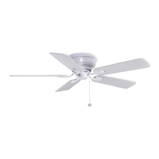
Page 1: Ceiling Fan
117 391 Hawkins Ceiling Fan Owner’s Manual Hawkins Ventilador de Techo de 1,12 Manual del Propietario... -
Page 2: Table Of Contents
44” Hawkins Thank you for purchasing our ceiling fan. This product has been manufactured with the highest standards of safety and quality. Ceiling Fan by Hampton Bay Date Purchased Store Purchased Table of Contents Safety Rules ....1 117-391 UL Model No. -
Page 3: Safety Rules
Safety Rules - Read and Save These Instructions To reduce the risk of electric shock, insure electricity has been turned off After making electrical connections, spliced conductors should be turned at the circuit breaker or fuse box before beginning. upward and pushed carefully up into outlet box. The wires should be spread apart with the grounded conductor and the equipment-grounding All wiring must be in accordance with the National Electrical Code conductor on one side of the outlet box and ungrounded conductor on the... -
Page 4: Unpacking Your Fan
Unpacking Your Fan Unpack your fan and check the contents. You should have the following items: Set of blades (5) Motor housing Blade Attachment Hardware (16 Screws with Fiber Washers) Mounting bracket Blade arms (5) Electrical Hardware Fan motor assembly Pull chain and fob (3 Plastic Wire Nuts) WARNING... -
Page 5: Installing Your Fan
Installing Your Fan Tools Required Figures 1 and 2 are examples of different ways to mount the outlet box. Phillips screwdriver, straight slot screwdriver, adjustable wrench, step ladder, and wire cutters. Outlet Box Mounting Options Outlet Box If there isn't an existing UL listed mounting box, then read the following instructions. -
Page 6: Hanging The Fan
Hanging the Fan Connect the ground cnductor of the 120V supply (this may be a bare wire or a wire with green colored insulation) to the green ground REMEMBER to turn off the power. Follow the lead(s) of the fan (Figure 6). steps below to hang your fan properly. - Page 7 WARNING Finishing the Fan TO REDUCE THE RISK OF FIRE OR ELECTRIC Installation SHOCK. DO NOT USE THIS FAN WITH ANY SOLID-STATE SPEED CONTROL DEVICE. Studs Move fan into position over the four mounting studs and secure with the provided washers and SUPPLY CIRCUIT nuts (Fig.
-
Page 8: Attaching The Fan Blades
Attaching the Fan Blades Screws with Fiber Washers Motor Step 1. Attach blades to blade arms using three screws with fiber washers. (Fig. 9) Start a screw into the blade arm, do not tighten. Repeat for the 2 remaining screws and washers. Blade Assembly Slot Step 2. -
Page 9: Blade Balancing
Blade Balancing The following procedure should correct most fan wobble. Check after each step. Touching Ceiling Check that all blade and blade arm screws are secure. Most fan wobble problems are caused when blade levels are unequal. Check this level by selecting a point on the ceiling above the tip of one of the blades. -
Page 10: Operating Your Fan
Operating Your Fan NOTE WAIT FOR FAN TO STOP BEFORE REVERSING Warm weather - (Counter Clockwise Direction) THE DIRECTION OF THE BLADE ROTATION. A downward air flow creates a cooling effect as shown in Figure 12. This allows you to set your air conditioner on a higher setting without affecting Turn on the power and check the operation of the fan. -
Page 11: Care Of Your Fan
Care of Your Fan Troubleshooting PROBLEM SOLUTION Here are some suggestions to help you maintain your fan. Fan will not start Check main and branch circuit fuses or breakers. Because of the fan's natural movement, some Check line wire connections to the fan and switch wire connections may become loose. -
Page 12: Specifications
Specifications FAN SIZE SPEED VOLTS AMPS WATTS N.W. G.W. C.F. 0.19 1540 5.7 kgs 6.3 kgs 44” MED. 0.31 2809 1.1’ (14.5 lbs) (13.9 lbs) HIGH 0.43 4286 These are approximate measures. They do not include Amps and Wattage used by the light kit . -
Page 13: Warranty Information
Lifetime Limited Warranty (lifetime warranty on motor) The Hampton Bay warrants the fan motor to be free from defects in workmanship and material present at time You must present a copy of the original purchase receipt to obtain warranty of shipment from the factory for a period of lifetime after the date of purchase by the original purchaser.
Need help?
Do you have a question about the 44 in Hawkins and is the answer not in the manual?
Questions and answers
replacement mounting bracket
To find a replacement mounting bracket for the HAMPTON BAY 44 in Hawkins ceiling fan, you can follow these steps:
1. Check the Manual: The manual mentions that the mounting bracket is a required component. Ensure you have the correct part number.
2. Contact Hampton Bay Support: Call the toll-free number 1-877-898-1881 for assistance in obtaining a replacement part.
3. Visit a Home Depot Store: Since Hampton Bay is a Home Depot brand, you may find replacement parts at a local store.
4. Look for Compatible Parts: Ensure that any replacement bracket is UL-listed and compatible with your ceiling fan model.
If the original bracket is unavailable, you may need to use a universal mounting bracket that meets safety standards.
This answer is automatically generated