Table of Contents

Related Manuals for LineEye SI-65

Summary of Contents for LineEye SI-65
- Page 1 Interface Converter Instruction Manual RS-422/485 SI-65 SI-65A SI-65A-L SI-65FA SI-65FA-L The CD-ROM attached to a product contains the newest English and Japanese instruction manuals in a PDF format. Please also refer to them. 3 rd...
- Page 2 This manual has been designed and edited with great care to give you all information. If you have any questions, feel free to direct your inquiries to LINEEYE. LINEEYE makes no warranty or guarantee, either expressed or implied with respect to its quality, performance, merchantability, or fitness for a particular purpose. LINEEYE shall not be liable for direct, in-direct, special, incidental, or consequential damages resulting from any defect in the product.
- Page 3 Safety Information Be sure to read the following LINEEYE has developed and manufactured this product for purpose of using with electrical devices such as a computer, a personal device, a measurement device, semiconductor manufacturing equipment, a vending machine, a sequencer, display equipment and so on.
- Page 4 Do not use the damaged cables. Doing so may cause fire by overheating. Use the included AC adapter or ones specified by LINEEYE. Failure to do so may cause overheating, fire, an electric shock, or injury. Never touch the converters and cables while thunderbolts are occurring.
-
Page 5: Table Of Contents
Chapter 8 Warranty and 2-1. SI-65(A/FA) Overview and Features ..7 After-Sales Service ..40 2-2. SI-65 Panel Explanation ....9 8-1. Troubleshooting ......40 2-3. SI-65A Panel Explanation ... 10 8-2. Warranty and Repair ....42 2-4. SI-65FA Panel Explanation ..11 8-3. -
Page 6: Chapter 1 Before Using The Product
1-1. Unpacking and Product Composition Make sure of the following when unpacking the product. Please let your LINEEYE distributor or LINEEYE know if you find any damage to the product caused by transportation, or if there are accessories lacking. Converter... -
Page 7: Overview
1-3. Overview SI-65, SI-65A, and SI-65FA are communication converters which convert asynchronous communication on RS-422/485 into TCP/IP or UDP/IP communication on Ethernet. These converters have built-in Lantronix XPort at the LAN interface part and the RS- 422/485 interface supports 4-wire full duplex and 2-wire half duplex. Thus It can be applied to various systems which requires liability. -
Page 8: Chapter 2 Si-65(A/Fa) Usage
Chapter 2 SI-65(A/FA) Usage 2-1. SI-65(A/FA) Overview and Features SI-65 is a DC powered model. SI-65A is a DC powered model which is adaptive to cold district. SI-65FA has a built-in AC power supply and has a insulator between the interfaces (Ethernet and the RS-422/485). -
Page 9: Panel Explanation
SI 65 Name Explanation Note Power Supply LED It lights when the SI-65 is powered. “SD” lights when a data is transmitted from LAN to RS- Data Status LED 422/485 “SD/RD” lights when a data is transmitted from RS- 422/485 to LAN. -
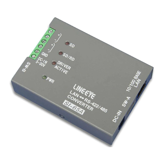
Page 10: Si-65A Panel Explanation
"I/O" means both directions to input and output. *3 Do not connect anything when using the half duplex mode. *4 Connect to GND (SG) of the target device [ 2-6. SI-65(A/FA) Cable Connection ] *5 About external power supply [ 2-7. SI-65(A) Power Source ] 2-3. - Page 11 "I/O" means both directions to input and output. *3 Do not connect anything when using the half duplex mode. *4 Connect to GND (SG) of the target device [ 2-6. SI-65(A/FA) Cable Connection ] *5 About external power supply [ 2-7. SI-65(A) Power Source ]...
-
Page 12: Si-65Fa Panel Explanation
2-4. SI-65FA Panel Explanation SI-65FA standard model (Model number: SI-65FA) 22.2 SI-65FA wall-hanging model (Model number: SI-65FA-L) 22.2 SI-65FA and SI-65FA-L have same function. About the detail of the shape of SI-65FA-L, please refer to “Attach on the wall (For SI-65FA-L)” at “7-8. Installation Method”. - Page 13 *2 "Out" means a direction to output signals from the converter. "In" means a direction to input signals to the converter. "I/O" means both directions to input and output. *3 Do not connect anything when using the half duplex mode. *4 Connect to GND (SG) of the target device [ 2-6. SI-65(A/FA) Cable Connection ]...
-
Page 14: A/Fa) Hardware Setup
2-5. SI-65(A/FA) Hardware Setup The two 4-position dip switches on the converter allows you to conduct the following setups: the line monitoring function, the driver control method, terminator enable/disable, and echo back enable/disable. SW-A No.1-3 (Baud Rate Setup) Following communication speed (baud rate) you wish to use, this setup is to set the internal timer used for the non-communication monitoring circuit and driver control circuit. - Page 15 SW-B Meaning No.1 Select a line mode RS-422 (full duplex) RS-485 (half duplex) No.2 Echo reception of transmission With echo back Without echo back data No.3 Terminal control between SD+ Without terminal With terminal and SD- control control(100 ohm) No.4 Terminal control between SD/ Without terminal With terminal...
-
Page 16: A/Fa) Cable Connection
2-6. SI-65(A/FA) Cable Connection Connect to the LAN connector of SI-65(A/FA) with a LAN cable of category 5 or more.→ [ 3-1. Connection to the Network ] RS-422/485 Connect RS-422/485 terminal block of SI-65(A/FA) and RS-422/485 signal line of the target device by using a twisted pair cable. -
Page 17: A) Power Source
AC 90 - 264 V, 50/60 Hz PSE/UL/CUL/GS/CCC/CE Note: When using VFN-650B (AC adapter), power consumption of AC is about 4.9VA for SI-65 and about 3.7VA for SI-65A. The operating temperature of the VFN-650B is from –10 to +50 degrees Celsius. When using SI- 65A at the temperature of –25 to –10 or +50 to +75 degrees Celsius, please do not use the AC... -
Page 18: Si-65Fa Power Source
2-8. SI-65FA Power Source 1. Prepare a power source of AC 85 - 264 V (50/60Hz). * Current consumption of SI-65FA is up to 40mA when AC is 100V and 24mA when AC is 240V. 2. Please confirm that there is no power supply on the cable, then open the cover of terminal block and connect the cables. -
Page 19: Chapter 3 Basic Configuration
Chapter 3 Basic Configuration 3-1. Connect to the LAN network Connect LAN connector of converter to the HAB/PC using LAN cable. LAN Cable LAN Cable(Cross Cable) * This converter does not have AutoMDI/MDI-X function to find the LAN port. To connect LAN port of PC directly, use the LAN cable with cross connection. -
Page 20: Default Ip Address
3-3. Default IP address As a factory setting, DHCP client mode and AutoIP function automatically set IP address. * When the IP address is 0.0.0.0 (factory setting), those functions are valid. When IP address is 0.0.1.0, only DHCP client function is valid. When having DHCP server in the network IP address is automatically set from the DHCP server when turning on the power of device. -
Page 21: Confirm Ip Address
3.Click [No] if following dialog is appeared. 3-5. Confirm IP address 1. Connect the converter to the network and turn on the power. 2. Open the DeviceInstaller from Start menu. 3. Device embedded with XPort is displayed on the main window. 4. -
Page 22: Assign Ip Address
3-6. Assign IP address 1.Click on IP assignment. 2.Select the method and then click [Next]. To valid the DHCP client and AutoIP address function. To set fixed IP address. When selecting When selecting [ Obtain an IP address automatically ] [ Assign a specific IP address ] 3. -
Page 23: Web Manager
Chapter 4 Configuration Using Web Manager 4-1. Web Manager Usage The configuration can be changed from a Web manager. For more details refer to [Xport User Guide (XPort_UG.pdf)] in the CD-ROM. Accessing from the deviceinstaller Select the device being set. Select [Web Configuration] tab and click [ ] icon. - Page 24 Web Manager Usage Server setting such as CPU Performance Serial Commnunication Conditions setting LAN Connection setting. After setting the various settings such as [Serial Settings], [Connection] etc.., click "OK" button. Then"Done!" will be displayed and the setup contents hold by Web Manager temporarily.
-
Page 25: Of Serial Port
4-2. Communication conditions of serial port 1.When using with baud rate 460800 or above, select "Server" and set High to "CPU Performance Mode". If baud rate is less than 460800, do not need to set it. 2.Select [Serial Settings]. Set "Protocol" to be "RS-232C" in serial side. Set Baud Rate, Data Bits, Parity, Stop Bits and Flow Control to be same as the target device. -
Page 26: Other Setting
4-4. Other Setting You can set various settings according to your usage. For more details refer to [ XPort User Guide (XPort_UG.pdf) ] in the CD-ROM. Pack Control The packing algorithms define how and when packets are sent to the network. Select [ Channel 1 ] -->[ Serial Settings ] and check [ Pack Control ]-->... -
Page 27: Chapter 5 Setup Example
Chapter 5 Setup Example 5-1. Server mode usage To use Device A (connected with the serial port of converter) through network connection by TCP connection request from a device on the network such as PC to the converter, please refer following setting. RS-485 (2 wire) Device A SD/RD+... -
Page 28: Client Mode Usage
5-2. Client Mode Usage To use the serial port of the Device B through network connection by TCP connection request from the converter to a server on the network when the converter has received a serial data of Device B, please refer following setting. RS-422 (4 wire) Device B Rx(+) -
Page 29: Using Two Units Of Converter
Stop bit 1bit, * Set the dip switches depending on the RS-485/RS-422 specification of the devices which connect to Converter 1 and 2. (2-5. SI-65(A/FA) hardware setup) Example of DeviceInstaller Setting Set a specific IP address to the converter 1. - Page 30 LAN Connection Mode (Server Mode: Enable, Client Mode: Enable) On converter 1, select “Connection” at the menu and select “With Any Character” at Active Connect. Then set the IP address of the converter 2 to “Remote Host” and port number of the converter 2 to “Remote Port”. Press OK after setting the values. Converter 1 192.168.0.75 On converter 2, select “Connection”...
-
Page 31: Chapter 6 Com Port Redirector
Chapter 6 COM Port Redirector 6-1. About Virtual COM Port The COM Port Redirector is the utility software to get the serial communication application not supporting the network connection to be able to use on the network. The redirector creates the virtual COM ports in Windows. Communications for these virtual COM ports are transferred to the serial port on the converter through the network. -
Page 32: Com Port Redirector
6-4. COM Port Redirector Connect the converter to the network. Login to the PC as administrator. 1. From start menu, go to "Lantronix" -> "CPR 4.x" -> "CPR Manager. "CPR Manager" window will be displayed. 2. Click [Com Port]-[Add and Remove] of toolbar to open the dialog to register/delete the virtual COM port. -
Page 33: Chapter 7 Documents
SI-DIN10 For SI-65FA For installation to 35mm DIN rail DIN vertical plate SI-DIN30S For SI-65 / SI-65A For vertical installation to 35mm DIN rail Magnet SI-MG70 For SI-65/SI-65A For more details about optional goods, please contact LINEEYE distirutors or LINEEYE. -
Page 34: Ordering Information
7-3. Ordering information Name Model Description SI-65 Japanese model *1 Interface Converter SI-65 SI-65-E Overseas model *2 SI-65-NS Converter and warranty only *3 SI-65A Japanese model *1 SI-65A-L Wall-mount model Interface Converter SI-65A SI-65A-E Overseas model *2 SI-65A-NS Converter and warranty only *3... -
Page 35: General-Purpose I/O Pins
To read the input status of CP2 on the general purpus I/O pin, send TCP/IP or UDP/IP command to the port number 30704. CP2 (RS-422/485 driver) control command of SI-65(A/FA) "xxh" in the sixth byte of command specifies the output status. "xxh" in the second byte of response shows the result. -
Page 36: How To Apply
IP address may not change. This method cannot reset the password. Operation of [ SILANIOinit ](configuration tool) 1.. Copy "SILANIOinit.exe" from the "/LINEEYE/SILANIOinit" folder in the utility CD to the appropriate folder (For example, "c:/data/"). 2. Set your device in the same network segment as your PC. - Page 37 Operation of DeviceInstaller Install DeviceInstaller to your PC and download the configuration file from the utility CD to the appropriate folder (For example, "c:/setup/"). [ 3-4. DeviceInstaller Usage] Set your device in the same network segment as your PC.(If your devices are not in the same network segment, you may not able to set.) Start Deveiceinstaller and click [Search] to display all XPort embedded Select your target device.
-
Page 38: Installation Method
Optional L bracket (SI-ML1) fitting condition DIN rail You can attach it to a 35mm DIN rail by using SI-DIN70 (optional) for SI-65/SI-65A or SI- DIN10 (optional) for SI-65FA. (SI-65FA-L does not support attachment to din rail.) 1. For SI-65/SI-65A, screw DIN rail mounting plate (SI-DIN70) to M3 screw halls on the bottom of the product. - Page 39 Usage of Wall bracket (SI-WM1) (For SI-65/SI-65A) With a wall bracket (SI-WM1, optional), you can fix the converter to a wall by screwing from the upper side of the bracket or hooking it to screws or nails hammered into the wall.
-
Page 40: Of Rs-422/485
Attach on the wall (For SI-65FA-L) SI-65FA-L can be hung on a wall by screwing from the top side. Note: SI-65FA-L does not support L bracket and DIN rail mounting plate. φ4 φ4.2 φ7 φ4.2 φ4 7-9. Transmission distance of RS-422/485 <Transfer Distance>... -
Page 41: Chapter 8 Warranty And After-Sales Service
Chapter 8 Warranty and After-Sales Service 8-1. Troubleshooting The "PWR" LED does not light. < When using the AC adapter > Check that you plug the AC adapter Is the AC adapter connected correctly? into the AC adapter plug or wall outlet correctly.Check the voltage of AC adapter. - Page 42 Cannot connect the converter from the network. Is the IP address and port number set Search the device by using the deviceinstaller and check correctly? the network address again. Is the converter connected to the other Assign IP Address of rooter to default gateway of the network segment beyond the rooter? converter.
-
Page 43: Warranty And Repair
8-2. Warranty and Repair Warranty Within a period of 12 months from the date of shipment, LINEEYE warrants that your purchased products (excepting consumable parts such as the batteries and software) are free of charge from any defects in material and workmanship, only when the products are operated in accordance with procedures described in the documents supplied by LINEEYE. - Page 44 There is a registration page on our web site. ( http://www.lineeye.com ) Please register your product for further support. We will provide you the firmware update information and sales information etc. LINEEYE CO., LTD. 4F., Marufuku Bldg., 39-1, Karahasi, Nishihiragaki-cho, Minami-ku, Kyoto, 601-8468, Japan TEL: 075-693-0161 FAX: 075-693-0163 URL: http://www.lineeye.com...
Need help?
Do you have a question about the SI-65 and is the answer not in the manual?
Questions and answers