Table of Contents
Advertisement
Available languages
Available languages
Quick Links
Advertisement
Chapters
Table of Contents

Related Manuals for VOLTCRAFT VC STK-3000


Summary of Contents for VOLTCRAFT VC STK-3000
- Page 1 Bedienungsanleitung VC STK-3000 Multifunktions- Schleifenprozesskalibrator Best.-Nr. 2389433 Seite 9 - 11 Operating Instructions VC STK-3000 Multifunction loop process calibrator Item No. 2389433 Page 22 - 41...
-
Page 2: Table Of Contents
Inhaltsverzeichnis Seite Einführung ................................4 Symbol-Erklärung ..............................4 Bestimmungsgemäße Verwendung ........................5 Lieferumfang ................................5 Merkmale und Funktionen ...........................6 Sicherheitshinweise .............................7 a) Allgemeine Hinweise .............................7 b) Betriebsumgebung ............................7 c) Vermeiden Sie Stromschlag, Schäden und die Entzündung von explosiven Gasen ........7 d) Schäden vermeiden ............................8 e) Batterien/Akkus .............................9 f) Netzteil ................................9 Bedienelemente und Komponenten ........................10... - Page 3 e) Frequenz ..............................16 f) Puls ................................16 11. Fernbedienungsmodus ............................17 12. Erweiterte Anwendung ............................17 a) Prozentsatz ..............................17 b) Steigung ..............................18 13. Anzeige ................................18 a) Eingangsanzeige ............................18 b) Ausgabeanzeige Output ..........................19 14. Wartung ................................19 a) Reinigung ..............................19 b) Kalibrierung ..............................20 c) Akkus/Batterien einsetzen oder austauschen .....................20 15.
-
Page 4: Einführung
1. Einführung Sehr geehrte Kundin, sehr geehrter Kunde, wir bedanken uns für den Kauf dieses Produkts. Dieses Produkt erfüllt die gesetzlichen nationalen und europäischen Anforderungen. Um diesen Zustand zu erhalten und einen sicheren Betrieb zu gewährleisten, müssen Sie als Anwender diese Bedi- enungsanleitung beachten! Diese Bedienungsanleitung gehört zu diesem Produkt. -
Page 5: Bestimmungsgemäße Verwendung
3. Bestimmungsgemäße Verwendung Das Produkt ist ein leistungsstarker, hochpräziser, handgeführter Multifunktions-Schleifenprozesskalibrator, der zur Schleifenkalibrierung und -reparatur eingesetzt werden kann. Er kann Gleichstrom und Spannung mit hoher Genauig- keit von 0,02 % ausgeben und messen. Es verfügt über die Funktion der automatischen Stufen- und Rampenausgabe. Diese Funktionen helfen Ihnen dabei die Linearität schnell zu erkennen. -
Page 6: Merkmale Und Funktionen
5. Merkmale und Funktionen • Ausgabe und Messgenauigkeit bis zu 0,02 %. • Es können „Prozentwerte“ ausgeben werden; Benutzer können verschiedene Prozentwerte einfach per Tasten- druck abrufen. • Es verfügt über die Funktion der automatischen Stufen- und Rampenausgabe. Diese Funktionen helfen Ihnen dabei die Linearität schnell zu erkennen. -
Page 7: Sicherheitshinweise
6. Sicherheitshinweise Lesen Sie sich die Bedienungsanleitung sorgfältig durch und beachten Sie insbesondere die Sicherheitshinweise. Sollten Sie die in dieser Bedienungsanleitung aufgeführten Sicherheitshin- weise und Informationen für einen ordnungsgemäßen Gebrauch nicht beachten, übernehmen wir keine Haftung für daraus resultierende Personen- oder Sachschäden. Darüber hinaus erlischt in solchen Fällen die Gewährleistung/Garantie. -
Page 8: D) Schäden Vermeiden
• Wenn Sie die Leitungen anschließen, schließen Sie zuerst die COM-Prüfspitze an und danach die andere Prüfspitze. Wenn Sie die Leitungen abtrennen, trennen Sie zuerst die stromführende Prüfspitze und dann die COM-Prüfspitze ab. • Öffnen Sie das Gehäuse des Kalibrators nicht. •... -
Page 9: E) Batterien/Akkus
e) Batterien/Akkus • Achten Sie beim Einlegen der Batterie/des Akkus auf die richtige Polung. • Entfernen Sie bei längerem Nichtgebrauch die Batterien/Akkus, um Beschädigungen durch Auslaufen zu vermeiden. Auslaufende oder beschädigte Batterien/Akkus können bei Hautkontakt Säureverätzun- gen hervorrufen. Beim Umgang mit beschädigten Batterien/Akkus sollten Sie daher Schutzhandschuhe tragen. -
Page 10: Bedienelemente Und Komponenten
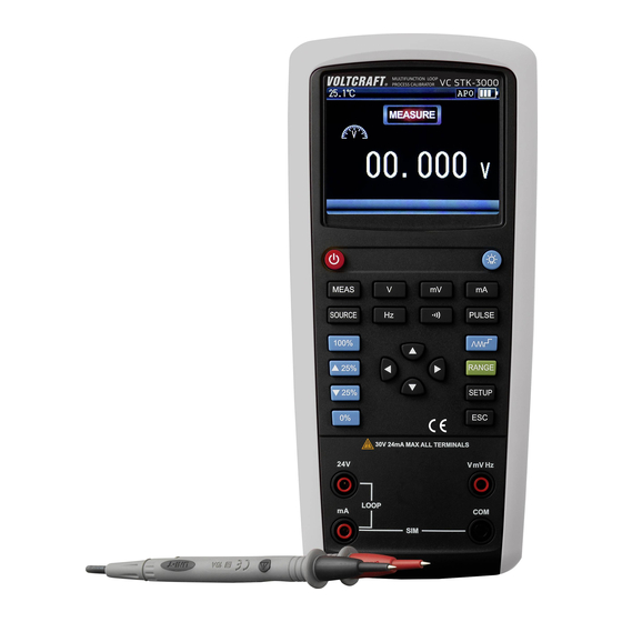
7. Bedienelemente und Komponenten a) Eingänge und Ausgänge Bezeichnung Beschreibung V, mV, Hz, , PULSE Mess-/Ausga- Schließen Sie die rote Prüfspitze an; schließen beanschluss Sie die schwarze Prüfspitze an. Schließen Sie die rote Prüfspitze an; schließen mA, SIM Mess-/Ausgabeanschluss Sie die schwarze Prüfspitze an. Schließen Sie die rote Prüfspitze an;... -
Page 11: C) Tastenbelegung
c) Tastenbelegung MULTIFUNCTION LOOP PROCESS CALIBRATOR 30V 24mA MAX ALL TERMINALS mV Hz LOOP Schlüssel Beschreibung Ein-/Ausschalten. Halten Sie die Taste für 2 Sekunden gedrückt. Hintergrundbeleuchtung einstellen. Messmodus. Moduswahl. Spannungsmessung/-Ausgang. Millivolt-Messung/-Ausgang. Milliampere-Messung/-Ausgabe. Drücken, um die Frequenzmessung/-ausgabe zu wählen. Durchgangsprüfung. Drücken, um die Pulsausgabe zu wählen. Kurz drücken, um den 100 %-Wert des aktuell eingestellten Bereichs auszugeben, gedrückt halten, um die 100 %-Werte zurückzusetzen. -
Page 12: System Konfigurieren
Pfeiltasten. Stellt den Cursor und den Parameter ein. Zyklusauswahl: Konstante Ausgabe 0 % - 100 % - 0 % bei geringer Steigung (langsam), automa- tisch wiederholen. Konstante Ausgabe 0 % - 100 % - 0 % bei hoher Steigung (schnell), automatisch wiederholen. -
Page 13: Messmodus
9. Messmodus Wenn sich der Kalibrator im „Ausgabemodus“ befindet, drücken Sie , um in den „Messmodus“ umzuschalten. a) Millivolt Drücken Sie , um Millivolt zu messen. Siehe nachstehende Abbildung zum Anschluss der Messleitungen. Millivolt-Messung Anschlüsse b) Betriebsspannung Drücken Sie , um die Spannung zu messen. Siehe nachstehende Abbildung zum Anschluss der Messleitungen. Spannungsmessung Anschlüsse c) Strom... -
Page 14: E) Frequenz
Schwarz Schleifenstrommessung Anschlüsse e) Frequenz Drücken Sie , um die Frequenz zu messen. Siehe nachstehende Abbildung zum Anschluss der Messleitungen. Frequenzmessung Anschlüsse f) Durchgang Drücken Sie , um den Durchgang zu messen. Siehe nachstehende Abbildung zum Anschluss der Messleitungen. OPEN Durchgangsmessung Anschlüsse Hinweis: Der Summer ertönt, wenn der Widerstand weniger als 250 Ω beträgt. -
Page 15: B) Betriebsspannung
Millivolt-Ausgang Anschlüsse b) Betriebsspannung Drücken Sie , um die Spannungsausgabe auszuwählen. Drücken Sie , um die Ausgabesstelle auszuwählen, dann drücken Sie , um den Wert einzustellen. Die nachstehenden Abbildungen zeigen die Spannungsausgabe und wie Sie die Messleitungen anschließen. Spannungsausgang Anschlüsse c) Strom Drücken Sie , um die Stromausgabe zu wählen. -
Page 16: E) Frequenz
Hinweis: Bei Überlast blinkt der Ausgabewert und „LOAD“ wird angezeigt. Überprüfen Sie aus Sicherheitsgründen, ob der Anschluss korrekt ist. e) Frequenz Drücken Sie , um die Frequenzausgabe zu wählen. Drücken Sie , um die Ausgabesstelle auszuwählen, dann drücken Sie , um den Wert einzustellen. 1. -
Page 17: Fernbedienungsmodus
11. Fernbedienungsmodus Schalten Sie anhand der Anleitung die PC-Steuerungsfunktion ein, stellen Sie die Parameter der seriellen Schnitts- telle auf dem PC ein und senden Sie den Protokollbefehl zur Steuerung des Kalibrators. Laden Sie die Software von www.conrad.com/downloads herunter. 12. Erweiterte Anwendung a) Prozentsatz Wenn sich der Kalibrator im Ausgabemodus befindet, drücken Sie kurz , um den... -
Page 18: B) Steigung
b) Steigung Die automatische Ausgabefunktion der Steigung kann ständig ein dynamisches Signal an den Sender liefern. Wenn Sie drücken, erzeugt der Kalibrator eine konstante und wiederholte Steigung (0 % - 100 % - 0%). Es gibt 3 Arten von Steigungen: 1) 0 % - 100 % - 0 % 40 Sekunden, gleichmäßige Steigung. -
Page 19: B) Ausgabeanzeige Output
b) Ausgabeanzeige Output Anzeige Bereich Auflösung Genauigkeit 100 mV 0,01 mV ±(0,02 % +10) Gleichspannung 1000 mV 0,1 mV ±(0,02 % +10) 10 V 0,001 V ±(0,02 % +10) 20 mA bei 0 - 24 mA 0,001 mA ±(0,02 % +2) Gleichstrom 20 mA (SIM) bei 0 - 24 mA 0,001 mA... -
Page 20: B) Kalibrierung
b) Kalibrierung Kalibrieren Sie das Messgerät einmal im Jahr, um seine Leistung zu gewährleisten. c) Akkus/Batterien einsetzen oder austauschen Vergewissern Sie sich, dass das Gerät ausgeschaltet ist, bevor Sie die hintere Abdeckung des Kalibrators oder das Akkufach öffnen und dass die Messleitungen nicht angeschlossen sind. -
Page 21: B) Batterien/Akkus
b) Batterien/Akkus Sollten sich noch Batterien/Akkus in dem Produkt befinden, nehmen Sie diese heraus und führen Sie sie einer aus- gewiesenen Sammelstelle zu. Als Endverbraucher sind Sie gesetzlich (Batterieverordnung) zur Rückgabe aller ge- brauchten Batterien/Akkus verpflichtet. Eine gemeinsame Entsorgung mit dem Hausmüll ist untersagt. Schadstoffhaltige Batterien/Akkus sind mit dem nebenstehenden Symbol gekennzeichnet, das auf das Verbot der gemeinsamen Entsorgung mit dem Hausmüll hinweist. Die Bezeichnungen für das auss- chlaggebende Schwermetall sind: Cd = Cadmium, Hg = Quecksilber, Pb = Blei (die Bezeichnung steht auf den Batterien/Akkus z.B. - Page 22 Table of contents Page Introduction ................................24 Explanation of symbols ............................24 Intended use ..............................25 Delivery content ..............................25 Features and functions ............................26 Safety instructions .............................27 a) General information .............................27 b) Operating environment ..........................27 c) Prevent electric shock, damage, explosive gas ignition ................27 d) Prevent damage ............................28 e) (Rechargeable) batteries ..........................29 f) Power adapter .............................29...
- Page 23 e) Frequency ..............................36 f) Pulse ................................36 11. Remote mode ..............................36 12. Advanced application ............................37 a) Percentage ..............................37 b) Slope ................................37 13. Indicator ................................38 a) Input indicator ..............................38 b) Output indicator ............................38 14. Maintenance ..............................39 a) Cleaning ..............................39 b) Calibration ..............................39 c) Installing or replacing the battery .........................39 15.
-
Page 24: Introduction
1. Introduction Dear customer, Thank you for purchasing this product. This product complies with the statutory national and European requirements. To maintain this status and to ensure safe operation, you as the user must observe these operating instructions! These operating instructions are part of this product. They contain important notes on commissioning and handling. -
Page 25: Intended Use
3. Intended use The product is a high-performance, high-accuracy, handheld, multifunctional loop calibrator, which can be used in loop calibration and repair. It can output and measure direct current and voltage with a high accuracy of 0.02%. It has the functionalities of automatic stepping and automatic sloping output. These functionalities help you to rapidly detect the linearity. -
Page 26: Features And Functions
5. Features and functions • Output and measurement accuracy up to 0.02%. • It can output “Percentage”; users can easily get different percentage values by pressing a button. • It has the functionality of automatic stepping and automatic sloping output. These functionalities help you to rapidly detect the linearity. -
Page 27: Safety Instructions
6. Safety instructions Read the operating instructions carefully and especially observe the safety information. If you do not follow the safety instructions and information on proper handling in this manual, we assume no liability for any resulting personal injury or damage to property. Such cases will invalidate the warranty/guarantee. -
Page 28: D) Prevent Damage
• Before using the calibrator, please ensure that the battery door is tightly closed. Please refer to “Main- tenance”. • When the battery power is insufficient , replace or charge the battery as soon as possible to avoid wrong reading value which may cause electric shock. Before opening the battery door, first remove the calibra- tor from “Dangerous Zone”. -
Page 29: E) (Rechargeable) Batteries
e) (Rechargeable) batteries • Correct polarity must be observed while inserting the (rechargeable) battery. • The (rechargeable) batteries should be removed from the device if it is not used for a long period of time to avoid damage through leaking. Leaking or damaged (rechargeable) batteries might cause acid burns when in contact with skin, therefore use suitable protective gloves to handle corrupted (rechargeable) batteries. -
Page 30: Operating Elements
7. Operating elements a) Input and output terminals Name Description V, mV, Hz, , PULSE measurement/ Connect red probe; connect black probe. output port mA, SIM measurement/output port Connect red probe; connect black probe. LOOP measurement port Connect red probe; connect black probe. -
Page 31: C) Keys
c) Keys MULTIFUNCTION LOOP PROCESS CALIBRATOR 30V 24mA MAX ALL TERMINALS mV Hz LOOP Description Power on/off. Long press the button for 2s. Adjust backlight. Measurement mode. Mode selection. Voltage measurement/output. Millivolt measurement/output. Milliampere measurement/output. Short press the button to choose frequency measurement/output. Continuity test. -
Page 32: System Setup
Arrow keys. Adjust the cursor and parameter. Cycle selection: Constantly output 0%-100%-0% at low slope (slow), repeat automatically. Constantly output 0%-100%-0% at high slope (fast), repeat automatically. At 25% of the step, step output 0%-100%-0%, repeat automatically. Switch range. Short press to set up the parameter, long press to enter Menu. ESC. -
Page 33: Measurement Mode
9. Measurement mode If the calibrator is in “Output” mode, press to switch to “Measurement Mode”. a) Millivolt Press to measure millivolt. Refer to the figure below for connecting the test leads. Millivolt measurement Connection b) Voltage Press to measure the voltage. Refer to the figure below for connecting the test leads. Voltage measurement Connection c) Current... -
Page 34: E) Frequency
Black Loop current measurement Connection e) Frequency Press to measure the frequency. Refer to the figure below for connecting the test leads. Frequency measurement Connection f) Continuity Press to measure the continuity. Refer to the figure below for connecting the test leads. OPEN Continuity measurement Connection... -
Page 35: B) Voltage
Millivolt output Connection b) Voltage Press to select voltage output. Press to choose output digit, then press to set the value. The figures below show voltage output and how to connect the test leads. Voltage output Connection c) Current Press to select current output. -
Page 36: E) Frequency
Note: If overload, the output value will flicker, the character “LOAD” will display, in this situation, you should check if the connection is correct for safety. e) Frequency Press to select frequency output. Press to choose output digit, then press to set the value. -
Page 37: Advanced Application
12. Advanced application a) Percentage When the calibrator is in output mode, short press to rapidly output percentage value accordingly, the 0% or 100% value of each output functionality is as follows: Output Functionality 0% value 100% value Millivolt 100 mV 0 mV 100 mV Millivolt 1000 mV... -
Page 38: Indicator
13. Indicator Unless otherwise specified, the calibration period of all indicators is one year, the applicable temperature is +18 °C to +28 °C, and the warm-up time is assumed as 30 minutes. a) Input indicator Indicator Range Resolution Accuracy 200 mV 0.01 mV ±(0.02%+ 5) DC Voltage... -
Page 39: Maintenance
Note: 1. For those temperatures that are not within +18 °C to +28 °C (i.e., -10 °C to +18 °C and +28 °C to 55 °C), the temperature coefficient is 0.005% FS/°C. 2. The max load of DC voltage output is 1 mA or 10 kΩ, the smaller load shall prevail. 3. -
Page 40: Disposal
15. Disposal a) Product This symbol must appear on any electrical and electronic equipment placed on the EU market. This symbol indicates that this device should not be disposed of as unsorted municipal waste at the end of its service life. -
Page 41: Technical Data
16. Technical data The maximum voltage between the terminal and earth line, or any two terminals is 30 V. Power supply ............6x Ni-MH AA-sized battery Range selection ..........manually Operating temperature ........-10 to +55 °C Storage temperature .........-20 to +70 °C Relative humidity ..........≤90 % (0 to +30 °C), ≤75 % (+30 to +40 °C), ≤50 % (+40 to +50 °C) Operating altitude ..........0 –... - Page 44 Dies ist eine Publikation der Conrad Electronic SE, Klaus-Conrad-Str. 1, D-92240 Hirschau (www.conrad.com). Alle Rechte einschließlich Übersetzung vorbehalten. Reproduktionen jeder Art, z. B. Fotokopie, Mikroverfilmung, oder die Erfassung in elektronischen Datenverarbeitungsanlagen, bedürfen der schriftlichen Genehmigung des Herausgebers. Nachdruck, auch auszugsweise, verboten. Die Publikation entspricht dem technischen Stand bei Drucklegung. Copyright 2016 by Conrad Electronic SE.
Need help?
Do you have a question about the VC STK-3000 and is the answer not in the manual?
Questions and answers