Table of Contents
Advertisement
Quick Links
Advertisement
Chapters
Table of Contents
Troubleshooting

Subscribe to Our Youtube Channel
Related Manuals for Tennant 3640E


Summary of Contents for Tennant 3640E
- Page 1 3640E Service Manual 330565 Rev. 00 (5- -00) Home Find... Go To..
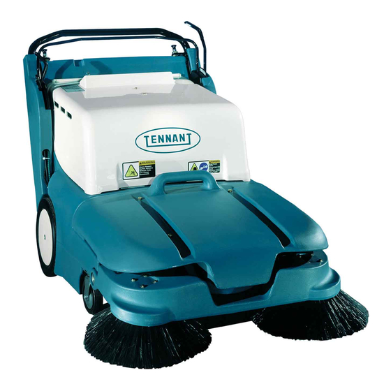
- Page 2 This service manual is intended to be an aid for the disassembly and reassembly of your TENNANT Model 3640E walk behind sweeper. The set is organized into four major groups: General Information, Chassis, Sweeping, and Electrical. General Information: Safety precautions, machine transport, machine jacking, machine storage, chassis lubrication, machine specifications, and machine maintenance chart.
-
Page 3: Table Of Contents
... . 1--13 THREAD SEALANT AND LOCKING COMPOUNDS ....1--13 3640E 330565 (5- -00) 1-- 1 Home Find... Go To.. - Page 4 GENERAL INFORMATION 1-- 2 3640E 330565 (5- -00) Home Find... Go To..
-
Page 5: Safety Precautions
FOR SAFETY: To identify actions that - - Avoid contact with battery acid. must be followed for safe operation of - - Use Tennant supplied or equivalent equipment. replacement parts. The machine is suited to sweep disposable WARNING: Heavy hopper. - Page 6 ON THE CONTROL PANEL THE BATTERY COMPARTMENT COVER BACK STRAIN LABEL - - LOCATED ON THE MOTOR COMPARTMENT COVER FLYING DEBRIS WARNING LABEL - - LOCATED ON THE MOTOR COMPARTMENT COVER 350842 1-- 4 3640E 330565 (5- -00) Home Find... Go To..
-
Page 7: Specifications
Maximum rated climb and descent angle Battery run time -- 130 Amp / hr 2.0 -- 3.0 hr Battery run time -- 215 Amp / hr 4.0 -- 5.0 hr 3640E 330565 (5- -00) 1-- 5 Home Find... Go To.. -
Page 8: Power Type
35 mm wide x 127 mm OD (1.375 in wide x 5 in OD) Rear (2) Solid 45 mm wide x 305 mm OD (1.75 in wide x 12 in OD) 1-- 6 3640E 330565 (5- -00) Home Find... Go To.. -
Page 9: Machine Dimensions
GENERAL INFORMATION 820 mm (32.25 in) 815 mm (32 in) 1475 mm (58 in) 960 mm (37.7 in) MACHINE DIMENSIONS 3640E 330565 (5- -00) 1-- 7 Home Find... Go To.. -
Page 10: Maintenance
200 Hours Battery terminals Clean and tighten 500 Hours Side brush motor(s) Check motor brush 1 (2) 1000 Main motor Check motor brush Hours LUBRICANT/FLUID ..Distilled water 1-- 8 3640E 330565 (5- -00) Home Find... Go To.. -
Page 11: Pushing Or Towing Machine
In Park. 1. Raise the main and side brushes. 2. Place the shift lever in the neutral position. (between reverse and second gear) 3. Push the machine using the handle assembly. 3640E 330565 (5- -00) 1-- 9 Home Find... Go To.. -
Page 12: Machine Tie Downs
MACHINE STORAGE When storing the machine for extended periods of time, the following procedures must be followed: 1. Raise the main and side brush(es). 2. Empty and clean the debris hopper. 1-- 10 3640E 330565 (5- -00) Home Find... Go To.. - Page 13 GENERAL INFORMATION 3. Fully charge the batteries. 07224 4. Disconnect the machine connector from the battery connector. 5. Store the machine in a clean dry area. 3640E 330565 (5- -00) 1-- 11 Home Find... Go To..
-
Page 14: Static Drag Chain
Make sure the chain is always touching the floor. Always use a internal tooth lock washer between the chain and rear guard to ensure a proper electrical connection. 1-- 12 3640E 330565 (5- -00) Home Find... Go To.. -
Page 15: Hardware Information
They include the following: 0.75 in 215--280 313--407 (291--380) (424--552) Locktite 515 sealant -- gasket forming material. TENNANT Part No. 75567,15 oz 1.00 in 500--650 757--984 (440 ml) cartridge. (678--881) (1026--1334) NOTE: Decrease torque by 20% when using a Locktite 242 blue -- medium strength thread thread lubricant. - Page 16 GENERAL INFORMATION 1-- 14 3640E 330565 (5- -00) Home Find... Go To..
- Page 17 TO REPLACE DRIVE BELT IDLER PULLEY ..... . . 2--32 3640E 330565 (5- -00) 2-- 1 Home Find... Go To..
- Page 18 CHASSIS 2-- 2 3640E 330565 (5- -00) Home Find... Go To..
-
Page 19: Introduction
CHASSIS INTRODUCTION This section includes information on the main chassis related components for example the rear wheels, casters, and transaxle. 2-- 3 3640E 330565 (5- -00) Home Find... Go To.. -
Page 20: Rear Tires And Wheels
3. Pull the hub cap off the drive wheel. 4. Pull the tire and wheel assembly off the drive axle. Be careful not to loose pin from axle cross hole. 2-- 4 3640E 330565 (5- -00) Home Find... Go To.. -
Page 21: To Install Rear Tire
3. Install the flat head screw in the end of the axle. Tighten to 7.6 -- 9.9 Nm (6 -- 8 ft lb). 4. Remove the blocks and lower the machine. 2-- 5 3640E 330565 (5- -00) Home Find... Go To.. -
Page 22: Casters
5. Install the two hex screws and tighten to 18 -- 24 Nm (15 -- 20 ft lb). 6. Remove the blocks and lower the machine. 7. Operate the machine and check the new caster for proper operation. 2-- 6 3640E 330565 (5- -00) Home Find... Go To.. -
Page 23: Shift Cable
1. Remove the filter cover from the rear of the machine. 2. Move the directional control lever to the park position. 3. Remove the handle stop bracket from the upper/left side of the filter compartment. 2-- 7 3640E 330565 (5- -00) Home Find... Go To.. - Page 24 Move the directional control lever out away from the mount plate. 7. Remove the cotter pin and clevis pin from the end of the shift cable. 2-- 8 3640E 330565 (5- -00) Home Find... Go To..
- Page 25 10. Remove the two hex screws holding the shift cable mount clamp to the machine frame. 11. Remove the shift cable mounting clamp from the cable. 2-- 9 3640E 330565 (5- -00) Home Find... Go To..
- Page 26 15. Place the cable and jam nuts in the slot of the mount plate with 2--3 threads showing above the upper nut. Firmly tighten the jam nuts. 2-- 10 3640E 330565 (5- -00) Home Find... Go To..
- Page 27 Re--tighten the jam nut against the cable ball end. 19. Reinstall the left side handle assembly cover plate. Tighten the three hex screws to 18 -- 24 Nm (15 -- 20 ft lb). 2-- 11 3640E 330565 (5- -00) Home Find... Go To..
- Page 28 22. Start the machine and check the shift lever for proper gear selection and operation. If the shift lever does not operate properly, see TO ADJUST SHIFT CABLE instructions in this section. 2-- 12 3640E 330565 (5- -00) Home Find... Go To..
-
Page 29: To Adjust Shift Cable
Pop the cable end off the ball end on the link. 3. Once the cable end is off the ball end, verify that the shift link is in the PARK detent. 2-- 13 3640E 330565 (5- -00) Home Find... Go To.. - Page 30 Re- -tighten the jam nut. 5. If more adjustment is needed, the shift cable can be adjusted at the two jam nuts behind the plastic handle cover or at the upper clevis. 2-- 14 3640E 330565 (5- -00) Home Find... Go To..
-
Page 31: Transaxle/Transmission
2. Place blocks under the machine frame. 3. Remove the rear cover from the drive belt. 4. Slip the main drive belt off the sheave on the transaxle. 2-- 15 3640E 330565 (5- -00) Home Find... Go To.. - Page 32 8. Remove the two hex screws holding the shift cable mount clamp to the machine frame. 2-- 16 3640E 330565 (5- -00) Home Find... Go To..
- Page 33 11. Spread the left handle leg out far enough to drop it down past the end of the left axle shaft. 12. Remove the left brush arm and wear ring from the machine frame. 2-- 17 3640E 330565 (5- -00) Home Find... Go To..
- Page 34 14. First drop the transaxle down out of the left side of the machine then pull it out of the right handle opening and right side brush arm. Remove the transaxle from the machine. 2-- 18 3640E 330565 (5- -00) Home Find... Go To..
-
Page 35: To Install Transaxle
Tighten to 7.6 -- 9.9 Nm (6 -- 8 ft lb). NOTE: Install 3 flat washers under the transaxle where the 30mm hex screw goes. 3. Position the left brush arm over the end of the left axle shaft. 2-- 19 3640E 330565 (5- -00) Home Find... Go To.. - Page 36 NOTE: The slot in the brush arm is used to adjust the taper of the main brush pattern. 7. Reinstall the shift cable on the ball end on the shift lever. 2-- 20 3640E 330565 (5- -00) Home Find... Go To..
- Page 37 Check for proper operation of the shifter and transaxle. Also check the main brush pattern and adjust if tapered. See TO CHECK AND ADJUST MAIN BRUSH PATTERN instructions in the SWEEPING section. 2-- 21 3640E 330565 (5- -00) Home Find... Go To..
-
Page 38: Transaxle Breakdown
CHASSIS TRANSAXLE BREAKDOWN 2-- 22 3640E 330565 (5- -00) Home Find... Go To.. -
Page 39: To Replace Flat Drive Belt
2. Remove the rear cover from the drive belt at the transaxle sheave. 3. Loosen the vacuum fan pivot bolt and remove the vacuum fan belt from the motor sheave. 2-- 23 3640E 330565 (5- -00) Home Find... Go To.. - Page 40 8. Adjust the belt stop so it just clears the flat belt when it is tight. This to stop the belt from moving when the machine is in neutral. 2-- 24 3640E 330565 (5- -00) Home Find... Go To..
- Page 41 18 -- 24 Nm (15 -- 20 ft lb). 11. Reinstall the rear belt cover on the machine. 12. Start the machine and operate the clutch bar. Check for proper engagement of the new belt and smooth operation. 2-- 25 3640E 330565 (5- -00) Home Find... Go To..
-
Page 42: To Replace Drive Belt Idler Cable (Clutch Handle Cable)
2. Remove the handle stop bracket from the upper/left side of the filter compartment. 3. Pull up on the two handle locks and move the handle assembly to its lowest position. 2-- 26 3640E 330565 (5- -00) Home Find... Go To.. - Page 43 Disconnect the spring from the cable. 7. Loosen the two jam nuts on the cable where it mounts to the bracket near the shaker motor. Slip the cable out of the mount slot. 2-- 27 3640E 330565 (5- -00) Home Find... Go To..
- Page 44 10. Remove the nut holding the clutch cable clamp to the cable lever mount plate. Note the position of the clamp and cable. 11. Remove the cable from the machine by pulling it toward the vacuum fan. 2-- 28 3640E 330565 (5- -00) Home Find... Go To..
- Page 45 14. Connect the tension spring from the idler arm to the end of the new drive belt idler cable. 15. Reinstall the cable in the clamp on the vacuum fan housing. 2-- 29 3640E 330565 (5- -00) Home Find... Go To..
- Page 46 18. Reinstall the left side cover plate. Tighten the three hex screws to 18 -- 24 Nm (15 -- 20 ft lb). 19. Move the handle assembly up to one of the four adjustment holes. 2-- 30 3640E 330565 (5- -00) Home Find... Go To..
- Page 47 Move the cable or cable bracket up or down and re--tighten the jam nuts. Close the cover and re--check. 2-- 31 3640E 330565 (5- -00) Home Find... Go To..
-
Page 48: To Replace Drive Belt Idler Pulley
2. Slip the drive belt off the transaxle sheave and idler pulley. 3. Remove the hex screw and nut holding the idler pulley to the idler arm. Remove the idler pulley. Retain the spring mount bracket. 2-- 32 3640E 330565 (5- -00) Home Find... Go To.. - Page 49 5. Slip the drive belt back over the transaxle sheave and the new idler pulley. 6. Lower the motor cover and operate the machine. Check the new idler for proper operation. 2-- 33 3640E 330565 (5- -00) Home Find... Go To..
- Page 50 CHASSIS 2-- 34 3640E 330565 (5- -00) Home Find... Go To..
- Page 51 ......3--44 TO REPLACE SIDE BRUSH HOUSING ..... 3--50 3-- 1 3640E 330565 (5- -00) Home Find... Go To..
- Page 52 SWEEPING 3-- 2 3640E 330565 (5- -00) Home Find... Go To..
-
Page 53: Introduction
The side brush sweeps debris in front of the machine and the main brush sweeps the debris into the hopper. The vacuum fan pulls air from the hopper and through the dust filter. 3-- 3 3640E 330565 (5- -00) Home Find... Go To.. -
Page 54: Debris Hopper
2. Lift on the handle and pull the hopper slightly up and forward. 3. Use your other hand to lift the front of the hopper. 4. Lift the hopper up and out of the machine frame. 3-- 4 3640E 330565 (5- -00) Home Find... Go To.. -
Page 55: To Install Debris Hopper
3. Push the hopper back until the two frame knobs are lined up with the two indentations in the hopper. The hopper is now in its correct position. 3-- 5 3640E 330565 (5- -00) Home Find... Go To.. -
Page 56: Options
NOTE: Do not attempt to lift the hopper when it is full of debris. Dump the debris from the hopper into a pile on the floor near a trash can or dumpster, then pick the debris up with a shovel. 3-- 6 3640E 330565 (5- -00) Home Find... Go To.. -
Page 57: Thermo Sentryt
1. Open the cover and engage the prop rod. 2. Locate the Thermo Sentryton the back wall just above the filter shaker motor. 3. Disconnect the wire from the terminals on the Thermo Sentryt. 3-- 7 3640E 330565 (5- -00) Home Find... Go To.. -
Page 58: Vacuum Wand
NOTE: The vacuum hose screws into the vacuum nozzle (left hand thread). Un- -screw to replace the hose. 3-- 8 3640E 330565 (5- -00) Home Find... Go To.. -
Page 59: Hopper Dust Filter
The optional filter is a panel style that can be cleaned and re--used multiple times. The optional filter also comes with a filter shaker system that can be used to shake the filter between cleanings. Panel filter 3-- 9 3640E 330565 (5- -00) Home Find... Go To.. -
Page 60: To Replace Filter Bag (Standard)3--10
2. Let the filter cover pivot down until it stops. NOTE: Remove the filter cover to empty any dirt that has collected. 3. Pull the filter bag off the 90_ air horn. Remove the filter bag from the machine. 3-- 10 3640E 330565 (5- -00) Home Find... Go To.. - Page 61 6. Reconnect the two filter clamps and snap them into the lock position. Reinstall the vacuum wand in the mount hole. 7. Start the machine and check the hopper filter area for any air leaks. 3-- 11 3640E 330565 (5- -00) Home Find... Go To..
-
Page 62: To Replace Panel Dust Filter (Optional)
2. Let the filter cover pivot down until it stops. NOTE: Remove the filter cover to empty any dirt that has collected. 3. Un--snap the catch lock on the filter lock bars. 3-- 12 3640E 330565 (5- -00) Home Find... Go To.. - Page 63 9. Reconnect the two filter clamps and snap them into the lock position. Reinstall the vacuum wand in the mount hole. 10. Start the machine and check the hopper filter area for any air leaks. 3-- 13 3640E 330565 (5- -00) Home Find... Go To..
-
Page 64: Main Brush
2. Go to the left side of the machine and locate the main brush idler side knob pin. This pin is located in the brush arm, just ahead of the LH drive wheel. 3-- 14 3640E 330565 (5- -00) Home Find... Go To.. - Page 65 5. After the main brush has been removed from the machine, remove the bearing assembly from the idler side end of the brush. 6. Install the bearing assembly in either end of the new brush. 3-- 15 3640E 330565 (5- -00) Home Find... Go To..
- Page 66 A detent type lock should be felt. 10. Reinstall the debris hopper and operate the machine. Check the taper of the main brush and adjust if needed. See TO ADJUST MAIN BRUSH instructions. 3-- 16 3640E 330565 (5- -00) Home Find... Go To..
-
Page 67: To Check And Adjust Main Brush Pattern
Re--tighten the hardware to 18 -- 24Nm (15 -- 20 ft lb). 6. Follow steps 1 thru 4 to re--check the brush pattern. 3-- 17 3640E 330565 (5- -00) Home Find... Go To.. -
Page 68: To Replace Main Brush Lift Cable
3. Remove the three hex screws holding the cover plate to the inside of the right side handle tower. Remove the cover plate from the machine. 3-- 18 3640E 330565 (5- -00) Home Find... Go To.. - Page 69 Locate the end of the main brush lift cable where it attaches to the mount bracket below the vacuum fan. Remove the cotter pin and clevis pin from the lift cable and brush lift arm. 3-- 19 3640E 330565 (5- -00) Home Find... Go To..
- Page 70 NOTE: Add a cable tie around the new main brush lift cable and the existing side brush lift cable. This will prevent the side brush lift cable from drooping down and rubbing on the brush drive pulley. 3-- 20 3640E 330565 (5- -00) Home Find... Go To..
- Page 71 15. Go up to the main brush lift lever and install the nut on the main brush lift cable mount clamp. Tighten the nut to 7.6 -- 9.9 Nm (6 -- 8 ft lb). 3-- 21 3640E 330565 (5- -00) Home Find... Go To..
- Page 72 18. Reinstall the right side handle assembly cover plate. Tighten the three hex screws to 18 -- 24 Nm (15 -- 20 ft lb). 19. Reinstall the left hand battery. 3-- 22 3640E 330565 (5- -00) Home Find... Go To..
- Page 73 23. Close the battery cover. 3-- 23 3640E 330565 (5- -00) Home Find... Go To..
-
Page 74: To Replace Main Brush Drive Belt
3. Remove the flat head screw holding the hub cap and drive wheel to the axle. Pull the tire and wheel assembly off the drive axle. Be careful not to loose pin from axle cross hole. 3-- 24 3640E 330565 (5- -00) Home Find... Go To.. - Page 75 First, loop it over the motor sheave, then, sheave over the main brush drive plug sheave, then, the idler sheaves. Front of machine Idler pulleys Flat belt Main brush drive sheave 3-- 25 3640E 330565 (5- -00) Home Find... Go To..
- Page 76 Put machine in Park and install hub/wheel assembly. 11. Install the main brush. See TO REPLACE MAIN BRUSH instructions. Lower the machine and operate the main brush. Check for proper operation. 3-- 26 3640E 330565 (5- -00) Home Find... Go To..
-
Page 77: To Replace Main Brush Drive Belt Idler Bearings
3. Remove the flat head screw holding the hub cap and drive wheel to the axle. Pull the tire and wheel assembly off the drive axle. Be careful not to loose pin from axle cross hole. 3-- 27 3640E 330565 (5- -00) Home Find... Go To.. - Page 78 7. Remove the hex nut or hex screw holding the idler pulley to the idler arm. Remove the idler pulley from the machine. 3-- 28 3640E 330565 (5- -00) Home Find... Go To..
- Page 79 10. Place the main brush lift lever in the down position. 11. Remove the screw driver from the brush arm. Place the main brush lift lever in the up position. Reinstall the belt drive plate. 3-- 29 3640E 330565 (5- -00) Home Find... Go To..
- Page 80 Put machine in Park and install hub/wheel assembly. 13. Install the main brush. See TO REPLACE MAIN BRUSH instructions. 14. Lower the machine and operate the main brush. Check for proper operation. 3-- 30 3640E 330565 (5- -00) Home Find... Go To..
-
Page 81: To Replace Main Brush Drive Sheave
3. Remove the flat head screw holding the hub cap and drive wheel to the axle. Pull the tire and wheel assembly off the drive axle. Be careful not to loose pin from axle cross hole. 3-- 31 3640E 330565 (5- -00) Home Find... Go To.. - Page 82 7. Remove the screw holding the brush drive plug to the pulley shaft. Remove the drive plug and square key. 3-- 32 3640E 330565 (5- -00) Home Find... Go To..
- Page 83 Reinstall the screw and tighten to 7.6 -- 9.9 Nm (6 -- 8 ft lb). 11. Reinstall the main brush drive belt. Engine/motor sheave Front of machine Idler pulleys Flat belt Main brush drive sheave 3-- 33 3640E 330565 (5- -00) Home Find... Go To..
- Page 84 Park and install hub/wheel assembly. 15. Install the main brush. See TO REPLACE MAIN BRUSH instructions. 16. Lower the machine and operate the main brush. Check for proper operation. 3-- 34 3640E 330565 (5- -00) Home Find... Go To..
-
Page 85: To Replace Stainless Steel Brush Arm Wear Rings
2. Remove both rear tires. See TO REMOVE REAR TIRE instructions in the CHASSIS section. 3. Remove the hex screw, sleeve, and nut holding the brush shaft to both brush arms. 3-- 35 3640E 330565 (5- -00) Home Find... Go To.. - Page 86 Remove the right brush arm from the machine. The wear ring can now be replaced or cleaned. If the wear ring is loose----use RTV sealant between the ring and the frame. Reinstall the right brush arm. 3-- 36 3640E 330565 (5- -00) Home Find... Go To..
- Page 87 Place the main brush lift lever in the up position. Reinstall the belt drive plate. 11. Spread the handle legs out far enough to reinstall them up past the end of the transaxle shafts. 3-- 37 3640E 330565 (5- -00) Home Find... Go To..
- Page 88 Park and install hub/wheel assembly. 14. Install the main brush. See TO REPLACE MAIN BRUSH instructions. 15. Lower the machine and operate the main brush. Check for proper operation. 3-- 38 3640E 330565 (5- -00) Home Find... Go To..
-
Page 89: To Remove Main Brush Shaft
2. Go to the back of the machine and locate the brush shaft running between the left and right brush arms. 3. Remove the tension spring from the right side of the brush shaft. 3-- 39 3640E 330565 (5- -00) Home Find... Go To.. - Page 90 5. Remove the two hex screws, sleeves, and nuts holding the brush shaft to the upper pivot bar. Remove the brush shaft from the machine. 3-- 40 3640E 330565 (5- -00) Home Find... Go To..
-
Page 91: To Install Main Brush Shaft
4. Start the machine and check the main brush pattern. See TO CHECK AND ADJUST MAIN BRUSH PATTERN instructions. 5. Raise and lower the main brush. Check the brush linkage for any binding or hanging up. 3-- 41 3640E 330565 (5- -00) Home Find... Go To.. -
Page 92: Side Brush
2. Go under the side brush and locate the hair pin clip on the bottom of the side brush motor shaft. Pull the pin out. NOTE: Some early models have two spacer washers under the hairpin. 3-- 42 3640E 330565 (5- -00) Home Find... Go To.. - Page 93 6. Reinstall the hair pin clip in the bottom of the side brush motor shaft. 7. Start the machine and check the side brush for proper operation. 3-- 43 3640E 330565 (5- -00) Home Find... Go To..
-
Page 94: To Replace Side Brush Lift Cable
3. Remove the three hex screws holding the cover plate to the inside of the right side handle tower. Remove the cover plate from the machine. 3-- 44 3640E 330565 (5- -00) Home Find... Go To.. - Page 95 6. Remove the nut from the clamp holding the side brush cable to the mount plate. 7. Remove the debris hopper from the machine. 3-- 45 3640E 330565 (5- -00) Home Find... Go To..
- Page 96 11. Pull the spring and cable assembly out of the machine frame. 3-- 46 3640E 330565 (5- -00) Home Find... Go To..
- Page 97 14. Reconnect the cable to the side brush spring assembly. Reinstall the spring assembly on the frame. Tighten the two hex screws to 7.6 -- 9.9 Nm (6 -- 8 ft lb). 3-- 47 3640E 330565 (5- -00) Home Find... Go To..
- Page 98 17. Install the clevis pin and cotter pin in the end of the new cable where it attaches to the side brush lift lever. 18. Position the brush lift lever assembly back onto the right handle arm. 3-- 48 3640E 330565 (5- -00) Home Find... Go To..
- Page 99 21. Reinstall the filter cover and the handle stop bracket. 22. Start the machine and check the side brush lift cable for proper operation. 23. Close the battery cover. 3-- 49 3640E 330565 (5- -00) Home Find... Go To..
-
Page 100: To Replace Side Brush Housing
2. Lower the side brush(s). 3. Remove the side brush(es). See TO REPLACE LH OR RH SIDE BRUSH instructions in the SWEEPING section. 4. Un--plug the side brush motor(s) from the main electrical harness. 3-- 50 3640E 330565 (5- -00) Home Find... Go To.. - Page 101 7. Remove the two screws holding the side brush lift cable assembly to the side brush housing. 8. Remove the hex screw and sleeve from the left side of the side brush housing. 3-- 51 3640E 330565 (5- -00) Home Find... Go To..
- Page 102 NOTE: Push the housing down to install the hardware. Lift up on the front of the housing and push the side brush bracket toward the rear of the machine. Tighten the hardware. 3-- 52 3640E 330565 (5- -00) Home Find... Go To..
- Page 103 16. Reinstall the side brush(es). See TO REPLACE LH OR RH SIDE BRUSH instructions in the SWEEPING section. 17. Operate the machine and check the side brush for proper operation. 3-- 53 3640E 330565 (5- -00) Home Find... Go To..
-
Page 104: Skirts And Seals
1. Remove the hopper from the machine. See TO REMOVE DEBRIS HOPPER instructions. 2. Dump any debris from the hopper. 3. Remove the hex screws holding the skirt and retainer to the hopper lip. 3-- 54 3640E 330565 (5- -00) Home Find... Go To.. - Page 105 5. Position the new skirt and existing retainer on the hopper. Reinstall the hardware and tighten to 7.6 -- 9.9 Nm (6 -- 8 ft lb). 6. Reinstall the debris hopper. See TO INSTALL DEBRIS HOPPER instructions. 3-- 55 3640E 330565 (5- -00) Home Find... Go To..
-
Page 106: Rear Skirt
Machine; Stop On Level Surface, Place Shifter In Park. 1. Remove the hopper from the machine. See TO REMOVE DEBRIS HOPPER instructions. 2. Remove the main brush. See TO REPLACE MAIN BRUSH instructions. 3-- 56 3640E 330565 (5- -00) Home Find... Go To.. - Page 107 6. Reinstall the main brush. See TO REPLACE MAIN BRUSH instructions. 7. Reinstall the hopper in the machine. See TO INSTALL DEBRIS HOPPER instructions. 8. Operate the machine and check for proper sweeping operation. 3-- 57 3640E 330565 (5- -00) Home Find... Go To..
-
Page 108: Upper Hopper Seal
1. Remove the hopper from the machine. See TO REMOVE DEBRIS HOPPER instructions. 2. Lift the upper hopper seal up slightly and locate the plastic rivets holding the seal to the machine. 3-- 58 3640E 330565 (5- -00) Home Find... Go To.. - Page 109 Start by placing the body of the rivet in the hole first, then screw the center pin into the body until it snaps in place. 7. Reinstall the hopper in the machine. See TO INSTALL DEBRIS HOPPER instructions. 3-- 59 3640E 330565 (5- -00) Home Find... Go To..
-
Page 110: Main Brush Dust Seals
Machine; Stop On Level Surface, Place Shifter In Park. 1. Remove the hopper from the machine. See TO REMOVE DEBRIS HOPPER instructions. 2. Remove the main brush. See TO REPLACE MAIN BRUSH instructions. 3-- 60 3640E 330565 (5- -00) Home Find... Go To.. - Page 111 6. Install the seven plastic rivets in the mount holes. Start by placing the body of the rivet in the hole first, then push the center pin into the body until it snaps in place. 3-- 61 3640E 330565 (5- -00) Home Find... Go To..
- Page 112 SWEEPING 7. Reinstall the main brush. See TO REPLACE MAIN BRUSH instructions. 8. Reinstall the hopper in the machine. See TO INSTALL DEBRIS HOPPER instructions. 3-- 62 3640E 330565 (5- -00) Home Find... Go To..
-
Page 113: To Replace Right Brush Seal (Drive Belt Side)
2. Remove the main brush. See TO REPLACE MAIN BRUSH instructions. 3. Remove the hex screw holding the main brush drive plug to the shaft. Pull the drive plug off the shaft. 3-- 63 3640E 330565 (5- -00) Home Find... Go To.. - Page 114 8. Install the new right dust seal and plate assembly on the machine. Line up the holes in the new seal with the mount holes in the machine frame. 3-- 64 3640E 330565 (5- -00) Home Find... Go To..
- Page 115 7.6 -- 9.9 Nm (6 -- 8 ft lb). 11. Reinstall the main brush. See TO REPLACE MAIN BRUSH instructions. 12. Reinstall the hopper in the machine. See TO INSTALL DEBRIS HOPPER instructions. 3-- 65 3640E 330565 (5- -00) Home Find... Go To..
-
Page 116: Vacuum Fan
Machine; Stop On Level Surface, Place Shifter In Park. 1. Open the battery cover. 2. Remove the air duct running from the top of the vacuum fan to the front wall of the dust filter. 3-- 66 3640E 330565 (5- -00) Home Find... Go To.. - Page 117 V--belt from the pulley on the fan. 6. Remove the hex screw and nut holding the vacuum fan assembly to the pivot mount bracket. Remove the vacuum fan from the machine. 3-- 67 3640E 330565 (5- -00) Home Find... Go To..
-
Page 118: To Install Vacuum Fan Assembly
Install the hex screw and nut. Tighten so the vacuum fan can pivot freely for belt tensioning. 3. Install the bolt in the tension slot and vacuum fan housing. Leave loose for now. 3-- 68 3640E 330565 (5- -00) Home Find... Go To.. - Page 119 6. Reinstall the clamp and cable on the top of the vacuum fan housing. 7. Reinstall the air duct running from the top of the vacuum fan to the front wall of the dust filter. 3-- 69 3640E 330565 (5- -00) Home Find... Go To..
- Page 120 SWEEPING 8. Close the battery cover. 9. Start the machine and check the vacuum fan for proper operation. 3-- 70 3640E 330565 (5- -00) Home Find... Go To..
-
Page 121: To Replace Vacuum Fan Impeller
2. Remove the smaller hex screws holding the vacuum fan housing to the bearing backing plate. Pull the housing off the backing plate. 3. Hold the impeller from turning. Remove the hex nut from the impeller shaft. 3-- 71 3640E 330565 (5- -00) Home Find... Go To.. - Page 122 8. Reinstall the vacuum fan assembly in the machine. See TO INSTALL VACUUM FAN ASSEMBLY instructions. 9. Start the machine and check the vacuum fan for proper operation. 3-- 72 3640E 330565 (5- -00) Home Find... Go To..
-
Page 123: To Replace Vacuum Fan Impeller Bearings
2. Remove the smaller hex screws holding the vacuum fan housing to the bearing backing plate. Pull the housing off the backing plate. 3. Hold the impeller from turning. Remove the hex nut from the impeller shaft. 3-- 73 3640E 330565 (5- -00) Home Find... Go To.. - Page 124 7. Use a press to remove the impeller shaft and inner bearing from the bearing housing. Press the bearing and shaft in the direction of the fan shaft. 8. Press the second bearing out of the housing. 3-- 74 3640E 330565 (5- -00) Home Find... Go To..
- Page 125 12. Reinstall the bearing assembly on the backing plate. Reinstall the hardware and tighten to 7.6 -- 9.9 Nm (6 -- 8 ft lb). 3-- 75 3640E 330565 (5- -00) Home Find... Go To..
- Page 126 17. Reinstall the vacuum fan assembly in the machine. See TO INSTALL VACUUM FAN ASSEMBLY instructions. 18. Start the machine and check the vacuum fan for proper operation. 3-- 76 3640E 330565 (5- -00) Home Find... Go To..
-
Page 127: To Tension Vacuum Fan V--Belt
1 kg (2 lb) at belt midpoint. The proper deflection should be 5 mm (0.09 in).Tighten the tension bolt to 18 -- 24 Nm (15 -- 20 ft lb). 3-- 77 3640E 330565 (5- -00) Home Find... Go To.. - Page 128 SWEEPING 4. Close the battery cover. 5. Start the machine and check the vacuum fan for proper operation. 3-- 78 3640E 330565 (5- -00) Home Find... Go To..
-
Page 129: Machine Troubleshooting
Machine will not start Thermo Sentryt tripped Reset Thermo Sentryt Batteries not properly reconnected Connect properly after charging Batteries discharged Charge Battery disconnect button pushed Turn to the right to reset 3-- 79 3640E 330565 (5- -00) Home Find... Go To.. - Page 130 SWEEPING 3-- 80 3640E 330565 (5- -00) Home Find... Go To..
- Page 131 ....4--43 MAIN MOTOR TROUBLESHOOTING ..4--44 FILTER SHAKER TROUBLESHOOTING ..4--46 4-- 1 3640E 330565 (5- -00) Home Find... Go To..
- Page 132 ELECTRICAL 4-- 2 3640E 330565 (5- -00) Home Find... Go To..
-
Page 133: Introduction
ELECTRICAL INTRODUCTION This section includes information on machine electrical components such as relays, circuit breakers, switches, and wiring harness. 4-- 3 3640E 330565 (5- -00) Home Find... Go To.. -
Page 134: Electrical System
12V deep cycle batteries, main drive motor, filter shaker motor, side brush motor(s), circuit breakers, relays, and switches. The batteries on the model 3640E is a 12 volt wet deep cycle style. They are located in the main motor compartment, under the cover. -
Page 135: Batteries
SPECIFIC GRAVITY SPECIFIC GRAVITY BATTERY BATTERY at 27 C (80 F) at 27_ C (80_F) CHARGE CHARGE 1.280 100% Charged 1.230 75% Charged 1.190 50% Charged 1.150 25% Charged 1.110 Discharged 4-- 5 3640E 330565 (5- -00) Home Find... Go To.. -
Page 136: To Charge Batteries
3. Move the directional control lever into the PARK position. 4. Lift the battery cover to access the batteries. The support arm automatically engages when the cover is lifted all the way up. 4-- 6 3640E 330565 (5- -00) Home Find... Go To.. - Page 137 8. Plug the battery charger into the wall outlet. NOTE: If the red “ABNORMAL CYCLE” lamp lights when the TENNANT charger is plugged into a wall outlet, the charger cannot charge the battery and there is something wrong with the battery.
- Page 138 ELECTRICAL 9. The TENNANT charger will start automatically. When the batteries are fully charged, the TENNANT charger will automatically turn off. 10. After the charger has turned off, unplug the charger from the wall outlet. 07224 11. Unplug the charger connector from the battery connector on the machine.
-
Page 139: To Replace Batteries
1. Open the battery cover and engage the prop rod. 2. Unplug the connector on the battery harness from the machine connector. 3. Disconnect the battery cables from the battery posts. 4-- 9 3640E 330565 (5- -00) Home Find... Go To.. - Page 140 5. Install new batteries in the machine. Note the orientation of the positive and negative posts. 6. Reconnect the cables on the posts. 7. Plug the battery harness connector into the machine connector. 4-- 10 3640E 330565 (5- -00) Home Find... Go To..
-
Page 141: Instrument Panel
ELECTRICAL INSTRUMENT PANEL The model 3640E is not equipped with an instrument panel. The gauges, switches, warning lights, and circuit breakers are located on the top of the battery cover. These components can be accessed by lifting the battery cover and engaging the prop rod. -
Page 142: Hourmeter
Start: Turn the motor key clockwise as far as it will go. Release the key as soon as the motor starts. Stop: Turn the motor key counterclockwise. 4-- 12 3640E 330565 (5- -00) Home Find... Go To.. -
Page 143: Circuit Breakers
ELECTRICAL CIRCUIT BREAKERS The electrical circuits on the model 3640E are protected with resetable circuit breakers. The circuit breakers are located on the battery cover, in the instrument panel. TO REPLACE 15 AMP CIRCUIT BREAKER FOR SAFETY: Before Leaving Or Servicing Machine;... - Page 144 NOTE: The mount hole in the battery cover is ”D” shaped. Make sure to install the circuit breaker in the correct orientation. 7. Reconnect the wires to the back of the new circuit breaker. See schematic in this section. 4-- 14 3640E 330565 (5- -00) Home Find... Go To..
- Page 145 ELECTRICAL 8. Plug the battery harness connector into the machine connector. 9. Close the battery cover. Start the machine and check the new circuit breaker for proper operation. 4-- 15 3640E 330565 (5- -00) Home Find... Go To..
-
Page 146: To Replace 50 Amp Circuit Breaker
1. Open the battery cover and engage the prop rod. 2. Unplug the connector on the battery harness from the machine connector. 3. Locate the 50 amp circuit breaker on the left side of the cover. 4-- 16 3640E 330565 (5- -00) Home Find... Go To.. - Page 147 6. Install the new 50 amp circuit breaker on the battery cover. Note the orientation of the number ”50” on the face of the reset button. 7. Install the two hex screws and nuts. Lightly tighten. 4-- 17 3640E 330565 (5- -00) Home Find... Go To..
- Page 148 See schematic in this section. 9. Plug the battery harness connector into the machine connector. 10. Close the battery cover. Start the machine and check the new circuit breaker for proper operation. 4-- 18 3640E 330565 (5- -00) Home Find... Go To..
-
Page 149: To Replace Main Contactor
2. Unplug the connector on the battery harness from the machine connector. 3. Locate the main contactor on the front of the filter wall, behind the main drive motor. 4-- 19 3640E 330565 (5- -00) Home Find... Go To.. - Page 150 Remove the contactor. 7. Install the new contactor in the machine on the back wall of the filter area. 4-- 20 3640E 330565 (5- -00) Home Find... Go To..
- Page 151 See schematic in this section. 10. Plug the battery harness connector into the machine connector. 11. Close the battery cover. Start the machine and check the new main contactor for proper operation. 4-- 21 3640E 330565 (5- -00) Home Find... Go To..
- Page 152 1. Open the battery cover and engage the prop rod. 2. Unplug the connector on the battery harness from the machine connector. 3. Locate the relay block on the back wall, behind the main drive motor. 4-- 22 3640E 330565 (5- -00) Home Find... Go To..
- Page 153 Push the relay in all the way. 6. Plug the battery harness connector into the machine connector. 7. Close the battery cover. Start the machine and check the new relay for proper operation. 4-- 23 3640E 330565 (5- -00) Home Find... Go To..
-
Page 154: Electric Motors
ELECTRICAL ELECTRIC MOTORS The electrical motors on the model 3640E are designed to run on 24 volt battery power. The motors included are the main drive motor, shaker motor, and side brush motor(s). The main drive motor supplies power to the transaxle, vacuum fan, and main brush drive. - Page 155 5. Loosen the adjustment screw on the vacuum fan. Let the vacuum fan drop down and remove the V- -belt from the motor sheave. 6. Slip the flat drive belt off the motor sheave. 4-- 25 3640E 330565 (5- -00) Home Find... Go To..
- Page 156 10. Remove the two front motor mount bolts. Access this hardware by going into the brush wrap area and locating the two hardware dimples in the roof of the frame. 4-- 26 3640E 330565 (5- -00) Home Find... Go To..
- Page 157 12. The main drive motor can now be removed from the machine. 13. Remove the drive sheaves from both sides of the old motor and install them on the new motor in the same orientation. 4-- 27 3640E 330565 (5- -00) Home Find... Go To..
-
Page 158: To Install Main Drive Motor
3. Install the two rear motor mount bolts. Access this hardware by going to the rear of the machine and locating the two hardware dimples in front of the brush arm mount bracket and above the transaxle. 4-- 28 3640E 330565 (5- -00) Home Find... Go To.. - Page 159 CHASSIS section. 7. Reinstall the flat transaxle drive belt over the sheave on the left side of the drive motor. See TO REPLACE FLAT DRIVE BELT instructions in the CHASSIS section. 4-- 29 3640E 330565 (5- -00) Home Find... Go To..
- Page 160 10. Reinstall the front battery in the machine. 11. Plug the battery harness connector into the machine connector. 12. Close the battery cover. Start the machine and check the new main drive motor for proper operation. 4-- 30 3640E 330565 (5- -00) Home Find... Go To..
-
Page 161: To Replace Filter Shaker Motor (Option)
1. Open the battery cover and engage the prop rod. 2. Unplug the connector on the battery harness from the machine connector. 3. Locate the shaker motor on the back wall, behind the battery. 4-- 31 3640E 330565 (5- -00) Home Find... Go To.. - Page 162 7. Install the new shaker motor in the machine. Position it on the frame bracket and install the mount bracket. Tighten the hex screws to 18 -- 24 Nm (15 -- 20 ft lb). 4-- 32 3640E 330565 (5- -00) Home Find... Go To..
- Page 163 See schematic in this section. 9. Plug the battery harness connector into the machine connector. 10. Close the battery cover. Start the machine and check the new shaker motor for proper operation. 4-- 33 3640E 330565 (5- -00) Home Find... Go To..
-
Page 164: To Replace Side Brush Motor
2. Unplug the connector on the battery harness from the machine connector. 3. Remove the RH side brush. See TO REPLACE LH OR RH SIDE BRUSH instructions in the SWEEPING section. 4-- 34 3640E 330565 (5- -00) Home Find... Go To.. - Page 165 7. Position the new side brush motor and gear box in the machine. Line up the mount holes in the machine frame with the mount holes in the side brush motor. 4-- 35 3640E 330565 (5- -00) Home Find... Go To..
- Page 166 SWEEPING section. 11. Plug the battery harness connector into the machine connector. 12. Close the battery cover. Start the machine and check the new RH side brush motor for proper operation. 4-- 36 3640E 330565 (5- -00) Home Find... Go To..
-
Page 167: To Replace Side Brush Switch
2. Remove the handle stop bracket from the upper/left side of the filter compartment. 3. Pull up on the two handle locks and move the handle assembly to its lowest position. 4-- 37 3640E 330565 (5- -00) Home Find... Go To.. - Page 168 6. Mark and disconnect the wires leading to the side brush switch. 7. Remove the two screws and nuts holding the switch to the brush handle mount plate. Remove the side brush switch from the machine. 4-- 38 3640E 330565 (5- -00) Home Find... Go To..
- Page 169 Reinstall the hardware. 11. Reinstall the right side handle assembly cover plate. Tighten the three flat screws to 18 -- 24 Nm (15 -- 20 ft lb). 4-- 39 3640E 330565 (5- -00) Home Find... Go To..
- Page 170 13. Reinstall the filter cover. 14. Reinstall the handle stop bracket. 15. Start the machine and check the side brush for proper operation when the handle is placed in the down position. 4-- 40 3640E 330565 (5- -00) Home Find... Go To..
-
Page 171: Electric Motor Amp Draw Chart
" APPROX. 32 DC AMPS F 2 ND GEAR " APPROX. 34 DC AMPS F 3 RD GEAR " APPROX. 38 DC AMPS F REVERSE " APPROX. 33 DC AMPS 4-- 41 3640E 330565 (5- -00) Home Find... Go To.. -
Page 172: Electrical Schematic
(OPTIONAL) SIDE BRUSH RELAY 9C/GRN 17/YEL 13F/BLK HANDLE RIGHT SIDE BRUSH MOTOR 9D/GRN 18/ORA 13G/BLK LEFT SIDE BRUSH MOTOR 18A/ORA 13H/BLK OPTIONAL SIDE BRUSH STATIC MOTORS: 2.5 AMPS EACH GROUND ELECTRICAL SCHEMATIC 4-- 42 3640E 330565 (5- -00) Home Find... Go To.. -
Page 173: Troubleshooting
The troubleshooting charts that follow are organized so they lead you through the circuits. They include flow charts and instructions for you as to where to insert your test instruments. 4-- 43 3640E 330565 (5- -00) Home Find... Go To.. -
Page 174: Main Motor Troubleshooting
THE KEY SWITCH IN THE ON POSITION BATTERY REPLACE THE VOLTAGE KEY SWITCH DOES M1 CONTACTS CLOSE AFTER TURNING THE KEY SWITCH TO START AND THEN TO RUN ? REPLACE M2 CONTINUED ON NEXT PAGE... 4-- 44 3640E 330565 (5- -00) Home Find... Go To.. - Page 175 0 VOLTAGE BETWEEN 3/ORA AND ANY 13/BLK WIRE AFTER THE KEY SWITCH IS STARTED AND IN THE RUN POSITION ? BATTERY VOLTAGE REPLACE M1 CHECK MOTOR--- --- REPAIR OR REPLACE 4-- 45 3640E 330565 (5- -00) Home Find... Go To..
-
Page 176: Filter Shaker Troubleshooting
BETWEEN ANY 4/YEL AND ANY 14/BLU WHEN THE KEY SWITCH IS OFF WHILE PRESSING THE SHAKER MOTOR SWITCH BATTERY REPLACE THE VOLTAGE FILTER SHAKER SWITCH REPLACE THE SHAKER DONE MOTOR RELAY 4-- 46 3640E 330565 (5- -00) Home Find... Go To.. - Page 177 We Need Your Help... As part of Tennant’s Zero Defects Program, we want to know about errors you have found or suggestions you may have regarding our machine manuals. If you find an error or have a suggestion, please complete this postage-paid form and mail it to us.
- Page 178 Home Find... Go To..
- Page 179 We Need Your Help... As part of Tennant’s Zero Defects Program, we want to know about errors you have found or suggestions you may have regarding our machine manuals. If you find an error or have a suggestion, please complete this postage-paid form and mail it to us.
- Page 180 Home Find... Go To..
Need help?
Do you have a question about the 3640E and is the answer not in the manual?
Questions and answers