
Related Manuals for Loctite Zeta 7740

Summary of Contents for Loctite Zeta 7740
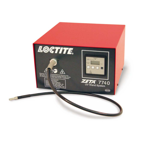
- Page 1 EQUIPMENT Operation Manual Loctite® Zeta® 7740 UV Curing Wand System Part Number 98157...
-
Page 2: Table Of Contents
TABLE OF CONTENTS 1. PLEASE OBSERVE THE FOLLOWING......................3 ............................3 MPHASIZED ECTIONS ...............................3 TEMS UPPLIED ............................3 AFETY , (I ) ....................4 IELD OF PPLICATION NTENDED SAGE 2. DESCRIPTION ...............................4 ...........................4 HEORY OF PERATION 1..............5 PERATING LEMENTS AND ONNECTIONS REFERS TO IGURE 3. -
Page 3: Please Observe The Following
Damage to the power cord or the housing can result in contact with live electrical parts. Check the power cord and housing before each use. If the power cord or unit is damaged, do not operate. The unit may be repaired only by a Loctite authorized service technician. -
Page 4: Field Of Application, (Intended Usage)
2.4 inches for the single light guide and 1.6 inches for a dual light guide. Field of Application, (Intended Usage) This Loctite® ZETA® 7740 UV Wand System is designed for use with light cure products that cure when exposed to ultraviolet and/or visible light. The system can be operated manually or in the timed mode and is capable of interfacing with a PLC controlled unit. -
Page 5: Operating Elements And Connections , Refers To Figure 1
Description (continued) Operating Elements and Connections, refers to Figure 1 1 Power Inlet Module Connect line cord to power inlet module. 2 Power Fuse Holder Fuse is located in the power module. 3 Power Switch 4 Foot Switch Connection Standard 9 pin “D” connector for foot switch or other external switch. 5 Light Guide Receptacle Is used to retain the light guide. - Page 6 Connection Input: 90-132 VAC, 50/60 Hz., 1.4 A @ 120 VAC Input: 180-265 VAC, 50/60 Hz, 0.7 A @ 240 VAC Lamp: 100 Watt Fuse: 4 Amp, 250 V Made in U.S.A., Technical Assistance: 1-800-Loctite Power Switch Fuse Holder Power...
-
Page 7: Technical Data
A space of 12" wide x 16" deep x 8" height is required. It is important to have at least 8 ® ® inches of space behind the unit to insure proper airflow. The Loctite ZETA 7740 UV Wand System only needs to be connected to a 120V/60Hz outlet to operate. -
Page 8: Operating The Unit
5. Operating the Unit 5.1 Inserting and Removing the Light Guides Caution! Be sure to remove the plastic end caps before attempting to use the light guide. Caution! If the free end of the light guide is secured at a fixed location, sharp bends should be avoided as it will cause a decrease in UV power. -
Page 9: Setting Exposure Time
5. Operating the Unit (continued) 5.3 Setting Exposure Time 5.3.1 Timed Mode 1. Set the mode to “timed,” by pressing the mode button until “T” appears on the display. 2. Set the timer to the desired UV exposure time. Depressing the buttons located under the display on the countdown timer sets exposure time. -
Page 10: Adjusting Dual Wand For Maximum Output
983684 Dual Light Guide, 1M 983800 Single Light Guide, 1.5M Item No. 98157 Objective ® Balance the UV output from the two light guides of Loctite P/N 984589. Tools Needed 3/32 inch hex key UV Radiometer – ® ® Loctite ZETA 7021 Radiometer;... -
Page 11: Using Foot Switch / Remote Device
20. Tighten set screw to lock the input end of the dual wand in position. Notice: If a radiometer is not available, it is recommended that Loctite Service be contacted at 1-800-LOCTITE (1-800-562-8483) to insure optimum performance when installing a new dual ended light guide. -
Page 12: Care And Maintenance
It is recommended that the end of the light guide be positioned no closer than ½ inch from the Loctite® product being cured. The heat transmitted by the lamp can adversely affect the properties of the cured product or possibly cause damaged to the part surface. -
Page 13: Troubleshooting
6.1 Replacing the Lamp Module (continued) WARNING! The UV lamp used in this unit contains a very small amount of mercury. Disposal of lamps should be done in accordance with state and local regulations. 7. Troubleshooting Type of Malfunction Possible Cause Correction Power does not come on –... -
Page 14: Documentation
8. Documentation Wiring Diagram White HOUR METER & TIMER Foot Switch Connector Solenoid 12V Fan 12V Fan 12V White + White - CLAMP DIODE LAMP Black 1N4006 Interlock Switch INPUT POWER MODULE Power Switch Black Black MODULE AC Inlet Black Black Blue Aux. -
Page 15: Replacement Parts And Accessories
Replacement Parts and Accessories Loctite Part Number Description 984818 Replacement Lamp Module 983677 Single End Light Guide (5 mm x 1M) 983684 Dual Ended Light Guide (3 mm x 1M) 983800 Single Light Guide (5 mm x 1.5M) 984770 Fan Filter Element, Quantity 5... -
Page 16: Warranty
9. Warranty Henkel expressly warrants that all products referred to in this Instruction Manual for the UV Wand System, (hereafter called “Product”), shall be free from defects in materials and workmanship. Liability for Henkel shall be limited, as its option, to replacing those Products which are shown to be defective in either materials or workmanship or to credit the purchaser the amount of the purchase price thereof (plus freight and insurance charges paid therefor by the user). - Page 17 Auburn Hills, Michigan 48326 Sao Paulo, Brazil www.loctite.com Loctite and Zeta are registered trademarks of Henkel Corporation, U.S.A © Copyright 2004. Henkel Corporation. All rights reserved. Data in this operation manual is subject to change without notice. P/N: 984339 Rev A, 04/2004...
Need help?
Do you have a question about the Zeta 7740 and is the answer not in the manual?
Questions and answers
Had an error, hit the reset button and put the time back in but now it doesn't count down or turn off. How can i fix this? there are a lot of items in the mode button that are not listed in this manual
exposure time screen reads "out mode P-1F" and i can't get it to work. what might the problem be?