Table of Contents
Advertisement
Advertisement
Chapters
Table of Contents

Related Manuals for American Sanders EZ-8


Summary of Contents for American Sanders EZ-8
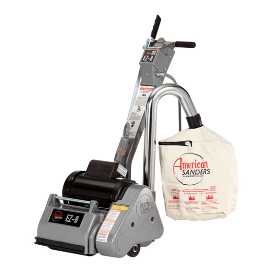
- Page 1 Drum Sander EZ-8 Operator’s Manual...
-
Page 2: Table Of Contents
This book has important information for the use and safe operation of this machine. Failure to read this book prior to operating or attempting any service or maintenance procedure to your American Sanders machine could result in injury to you or to other personnel; damage to the machine or to other property could occur as well. You must have training in the operation of this machine before using it. - Page 3 DANGER: Failure to read the Owner’s Manual prior to operating or servicing your American Sanders machine could result in injury to you or to other personnel; damage to the machine or to other property could occur as well. You must have training in the operation of this machine before using it.
-
Page 6: Introduction
Introduction Control Switch Operating Control Lever Dust Pipe Control Link Transport Handle Locking Collar Handle Latch Level Adjustment Drum Cover Model 07012A 07058A 07060A 07084A 07057A Abrasive Size 8 in x 19 in sleeve 8 in x 19 in sleeve 8 in x 19 in sleeve 8 in x 19 in sleeve Abrasive Rate... -
Page 7: Electrical Connection Instructions
Electrical Connection Instructions SAFETY INSTRUCTIONS This floor-finishing machine shall be grounded while in use to protect the operator from electrical shock. The machine is provided with a three-conductor cord and a three contact grounding attachment plug to fit the proper grounding type receptacle. -
Page 8: Machine Transportation
Machine Transportation Figure 1 Figure 2 Figure 4 Figure 3... -
Page 9: Machine Setup
Machine Set-up... - Page 10 Machine Setup This sanding machine is designed to be operated with a remote vacuum dust collection system or with the included dust bag. Preparing Remote Vacuum Dust Collection Systems 1.5" Hose from vacuum system 2" Hose from (not included) vacuum system To prepare the machine for remote vacuum dust collection systems that (not included) have a 2”...
-
Page 11: Operating Instructions
Operating Instructions Figure 11... -
Page 12: Adjustment Procedures
Adjustment Procedures Leveling To adjust the machine leveling follow this procedure: 1. Locate the leveling screw. See Figure 6. 2. Tighten the screw (compress the leveling spring) to sand heavier on drive belt side of sanding drum. 3. Loosen the leveling screw (relax the leveling spring) to sand heavier on the side opposite the drive belts. -
Page 13: Troubleshooting
Troubleshooting... - Page 14 Este manual contiene información importante acerca del uso y la seguridad de la máquina. Si no lee el manual antes de utilizar su máquina American Sanders o de intentar realizar los procedimientos de reparación o mantenimiento de la misma, usted o el resto del personal podrían sufrir lesiones;...
-
Page 15: Instrucciones De Seguridad Para El Operador
Instrucciones De Seguridad Para El Operador PELIGRO significa: Usted u otras personas pueden estar expuestos a sufrir lesiones personales, inclusive la muerte si las indicaciones de PELIGRO que se encuentran en esta máquina o en el manual de instrucciones se ignoran o no se tienen en cuenta. Lea y respete todas las indicaciones de PELIGRO que se encuentran en el manual de instrucciones y en la máquina. -
Page 17: Introducción
Introducción Palanca de control de Interruptor de control funcionamientor Collarín de cierre Enlace de control Manija de transporte Collarín de cierre Tubo para aspiración de polvo Ajuste del nivel Tapa del tambor Modelo 07012A 07058A 07060A 07084A 07057A Tamaño de abrasive (cm) 20.3 x 48.2 la manga 20.3 x 48.2 la manga 20.3 x 48.2 la manga... -
Page 18: Instrucciones De Conexión Eléctrica
Instrucciones De Seguridad Esta máquina para pisos de acabado deberá estar conectado a tierra mientras esté en uso para proteger al operador de una descarga eléctrica. La máquina está provista de un cable de tres conductores y un accesorio de conexión a tierra de tres contactos de enchufe para adaptarse al receptáculo de conexión a tierra adecuada. -
Page 19: Cómo Transportar La Máquina
Cómo transportar la máquina Figura 1 Figura 2 Figura 4 Figura 3... -
Page 20: Instalación De La Máquina
Instalación de la máquina Para instalar su máquina siga este procedimiento: 1. Familiarícese con la máquina y lea todas las indicaciones de peligro, advertencia y precaución. Asegúrese de que todos los operadores de la máquina hayan leído este manual de instrucciones. - Page 21 NOTA: Para lograr los mejores resultados, vacíe frecuentemente. Siga todas las advertencias incluidas en el manual y en la bolsa de polvo. -18- American Sanders Manual del operador (ES) - Super 7R...
-
Page 22: Operación De La Máquina
Operación de la máquina... -
Page 23: Mantenimiento De Rutina
Procedimientos de ajuste de la lijadora Nivelación Para nivelar la máquina: tome el tornillo de ajuste de la roldana pivotante “A” con una herramienta adecuada (pinzas, etc.). Usando una herramienta similar, afloje la tuerca de seguridad “B” medi- ante un movimiento en dirección contraria a las agujas del reloj. (Figura 6). Condición - La almohadilla crea salientes en los dos bordes o se experimenta un “salto”: Rote los tornillos de ajuste en igual medida en sentido de las agujas del reloj. -
Page 24: Resolución De Problemas
Resolución de problemas... - Page 25 LISEZ CE MANUEL Ce Manuel contient des informations importantes concernant l’utilisation et le fonctionnement de cette machine dans des conditions de sécurité optimales. La non-lecture de ce manuel avant d’utiliser ou d’entretenir votre machine American Sanders risque de provoquer un accident ou d’endommager la machine ou son environnement. Vous devez avoir été formé...
-
Page 26: Consignes De Securite Destinees A L'operateur
Consignes De Securite Destinees A L’operateur DANGER signifie: De graves blessures corporelles, voire la mort, peuvent survenir si les déclarations DANGER apposées sur l’appareil ou inscrites dans le Manuel de l’utilisateur sont ignorées ou ne sont pas suivies. Lisez et respectez toutes les consignes DANGER se trouvant dans le Manuel de l’utilisateur et sur l’appareil. -
Page 28: Introduction Et Caractéristiques De L'appareil
Introduction Levier de commande Interrupteur Tuyau à poussières Tige de commande Poignée de transport Collier de blocage Verrou du manche Réglage du niveau Couvre-tambour Modèle 07012A 07058A 07060A 07084A 07057A Dimension de abrasif (cm) 20.3 x 48.2 cm 20.3 x 48.2 cm 20.3 x 48.2 cm 20.3 x 48.2 cm 20.3 x 48.2 1/2 cm... -
Page 29: Consignes De Sécurité
Consignes De Sécurité... -
Page 30: Transport De L'appareil
Transport de l’appareil... -
Page 31: Préparation De L'appareil
Préparation de l’appareil Figure 5 Figure 6 Figure 7 Figure 8... - Page 32 Préparation de l’appareil TUYAU DE 2" DU SYS- TUYEAU DE 1.50" TEME D’ASPIRATION DU SYSTEME D’AS- (NON FOURNI) PIRATION (NON FOURNI) (30563A) TUYAU D’EVACUATION TUYAU DE 2" X ADAPTATEUR DE TUYAU DE 1.50" Figure 1 INSTALLEZ LE SAC A POUSSIERES EN APPUYANT SON EXTREMITE SUR LE TUYAU D’EVACUATION JUSQU’A CE QUE L’ANNEAU SE VERROUILLE DANS...
-
Page 33: Utilisation De L'appareil
Utilisation de l’appareil Figure 11... -
Page 34: Réglage De La Ponceuse
Réglage de la ponceuse Mise à niveau Pour régler la mise à niveau de l’appareil, exécutez les opérations suivantes : 1. Repérez la vis de mise à niveau (voir la figure 6). 2. Serrez la vis (en comprimant le ressort de mise à niveau) si vous désirez poncer plus fort sur le côté... -
Page 35: Dépannage
Dépannage... - Page 36 FloorCrafter Drum Sander EZ-8 Belt Sander Operator’s Manual Parts Manual Notes: ________________________________________________ ________________________________________________ ________________________________________________ ________________________________________________ ________________________________________________ ________________________________________________ ________________________________________________ ________________________________________________ ________________________________________________ ________________________________________________ ________________________________________________ ________________________________________________ ________________________________________________ ________________________________________________ ________________________________________________ ________________________________________________ ________________________________________________ ________________________________________________ ________________________________________________ ________________________________________________ ________________________________________________ ________________________________________________ ________________________________________________ 36 52...
- Page 37 EZ-8 Sander Section II Parts Manual...
-
Page 38: Handle Assy
HANDLE ASSEMBLY (07012A, 07058A, 07057A, 07084A) HANDLE ASSEMBLY (07012A, 07058A, 07057A, 07084A) RF059800 032117... - Page 39 STYLE (07057A) (07058A, 07057A, 07084A) 65706A LINK,CONTROL 47387B SWITCH TOGGLE DP3T W/WIRES 65707A LINK, CONTROL ADJUSTER 48905A WIRE ASM RELAY 3 WHT EZ-8 AS007700 TUBE, HANDLE, EZ-8 HDTR, HR 51523A BUSHING, STRAIN RELIEF METER (7012A) 71347A LABEL CCA WARNING (07058A, 69106A...
-
Page 40: Handle Assy
HANDLE ASSEMBLY (07060A) HANDLE ASSEMBLY (07060A) RF064600 090216... - Page 41 AS010100 LEVER, FEATHERING AUSTRALIA 65706A LINK,CONTROL 47387B SWITCH TOGGLE DP3T W/WIRES 65707A LINK, CONTROL ADJUSTER 48905A WIRE ASM RELAY 3 WHT EZ-8 69106A TUBE, HANDLE, EZ-8 51523A 70175A BUSHING, STRAIN RELIEF TAG WARNING ENG-SPN 71347A LABEL CCA WARNING 74052A PLATE WARNING...
-
Page 42: Base Assy
BASE ASSY... -
Page 44: Motor Assy
MOTOR ASSEMBLY MOTOR ASSEMBLY RF064800 032117... - Page 45 CORD, MOTOR, EZ-8, AUSTRALIA (07060A) 40542A CORD, MOTOR W, L6-15P (07012A) 41949A CORD MOTOR EZ-8 (07058A, 07057A, 07084A) 44642A MOTOR 1.5 HP 115V/60HZ EZ-8 (07012A, 07058A, 07057A) 41306A CAPACITOR RUN 115V EZ-8 41307A CAPACITOR START 115V EZ-8 47391A SWITCH THERMAL 115V EZ-8 44648A MOTOR 1.5 HP 240V/50HZ EZ-8 (07060A, 07084A)
-
Page 46: Dust Control Assy
DUST CONTROL ASSEMBLY DUST CONTROL ASSEMBLY RF064700 032117... - Page 47 IMPELLER EZ-8 66159A PULLEY FAN EZ-8 67457A SHAFT EZ-8 67612A DUST SHOE EZ-8 68285A SUPPORT, TUBE 80295A WASHER BOWED .516ID X 1.06OD 30563A 2" X 1.50" HOSE ADAPTOR (07057A, 07058A, 07060A, 07084A) AS015400 TUBE, ADAPTER EZ-8 ( 07060A) RF064700 032117...
-
Page 48: Sanding Drum Assy
SANDING DRUM ASSEMBLY (07012A, 07058A, 07060A, 07084A) Nameplate, Ez-8... - Page 49 BEARING FLANGE 1" 2 HOLE 64469A HANDLE, LIFTING 65310A KEY WASHER (EZ-8) 66161A PULLEY, DRUM, EZ-8 67459A SHAFT ARBOR CLAMP DRUM EZ-8 80027A BOLT RD HD SQ NECK 5/16X1 80295A WASHER BOWED .516ID X 1.06OD NAMEPLATE, EZ-8 AS014600 81211A NUT, 5/16-18 HEX SERRATED FLANGE...
-
Page 50: Wiring Diagram
Wiring Diagram... - Page 51 THE DESCRIPTION OF THE LIMITED WARRANTIES STATED WITHIN. NO OTHER WARRANTY, EXPRESSED OR IMPLIED, (1) The obligation of American Sanders under this warranty is limited INCLUDING BUT NOT LIMITED TO ANY IMPLIED WARRANTY to repairing or replacing, at its option, any part which is proven to...
- Page 55 American Sanders an AMANO Company 1 Eclipse Rd l PO Box 909 Sparta, North Carolina 28675 l USA www.pioneereclipse.com www.americansanders.com +1-336-372-8080 1-800-367-3550 Fax 1-336-372-2913 LT069300 © 2017 American Sanders EZ8_F...
Need help?
Do you have a question about the EZ-8 and is the answer not in the manual?
Questions and answers