Table of Contents
Advertisement
Quick Links
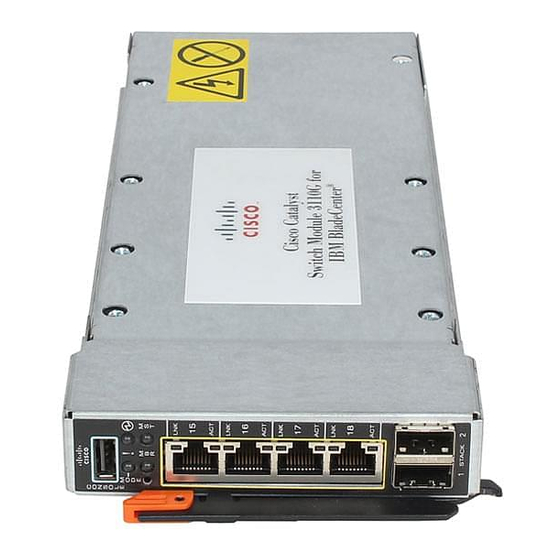
Cisco Catalyst Switch Module 3110G,
3110X, and 3012 for IBM BladeCenter
Hardware Installation Guide
April 2008
Americas Headquarters
Cisco Systems, Inc.
170 West Tasman Drive
San Jose, CA 95134-1706
USA
http://www.cisco.com
Tel: 408 526-4000
800 553-NETS (6387)
Fax: 408 527-0883
Text Part Number: OL-12192-01
Advertisement
Table of Contents

Related Manuals for Cisco 3110G


Summary of Contents for Cisco 3110G
- Page 1 Cisco Catalyst Switch Module 3110G, 3110X, and 3012 for IBM BladeCenter Hardware Installation Guide April 2008 Americas Headquarters Cisco Systems, Inc. 170 West Tasman Drive San Jose, CA 95134-1706 http://www.cisco.com Tel: 408 526-4000 800 553-NETS (6387) Fax: 408 527-0883 Text Part Number: OL-12192-01...
- Page 2 You can determine whether your equipment is causing interference by turning it off. If the interference stops, it was probably caused by the Cisco equipment or one of its peripheral devices. If the equipment causes interference to radio or television reception, try to correct the interference by using one or more of the following measures: •...
-
Page 3: Table Of Contents
Creating Switch Stacks Stacking Guidelines Connecting a Switch Stack Switch Stack Cabling Examples Installing Devices in the 10-Gigabit Ethernet Slot 2-11 Installing an X2 Transceiver Module 2-11 Catalyst Switch Module 3110G, 3110X, and 3012 for IBM BladeCenter Hardware Installation Guide OL-12192-01... - Page 4 Cable and Adapter Specifications 10-Gigabit Ethernet X2 Transceiver Module Cable Specifications Four Twisted-Pair Cable Pinouts Two Twisted-Pair Cable Pinouts Identifying a Crossover Cable N D E X Catalyst Switch Module 3110G, 3110X, and 3012 for IBM BladeCenter Hardware Installation Guide OL-12192-01...
-
Page 5: Preface
Cisco.com. For information about the standard Cisco IOS Release 12.1 or 12.2 commands, see the Cisco IOS documentation set from the Cisco.com home page at Technical Support and Documentation > Documentation. On the Cisco Documentation home page, select Release 12.1 or 12.2 from the Cisco IOS Software drop-down list. -
Page 6: Related Publications
3110X, and 3012 for IBM BladeCenter. This guide contains agency approvals, compliance information, and translated warning statements. Release Notes for the Cisco Catalyst Switch Module 3110G, 3110X, and 3012 for IBM BladeCenter. • The release notes include the system requirements, important notes, limitations, open and resolved caveats, and documentation updates. -
Page 7: Chapter 1 Product Overview
C H A P T E R Product Overview The Cisco Catalyst Switch Module 3110G, 3110X, and 3012 for IBM BladeCenter—referred to as the switch modules—are Ethernet switch modules that you install in an IBM BladeCenter enclosure—referred to as the blade enclosure. You can connect devices to the switch modules for connections to other network devices such as routers, servers, and other switches. -
Page 8: Hardware Features
1 internal 100BASE-T Ethernet management port Hardware Features The Catalyst Switch Module 3110G and 3110X include the 10/100/1000 Ethernet ports or the 10-Gigabit Ethernet module slot, console port, StackWise Plus ports, release latch, and the switch module LEDs shown in Figure 1-1 and described on the following pages. -
Page 9: 10/100/1000 Ethernet Ports
Release latch 10/100/1000 Ethernet Ports The Catalyst Switch Module 3110G and 3012 10/100/1000 Ethernet ports use standard RJ-45 connectors with Ethernet pinouts. The maximum cable length is 328 feet (100 meters). The 100BASE-TX and 1000BASE-T traffic requires Category 5, Category 5e, or Category 6 unshielded twisted pair (UTP) cable. -
Page 10: 10-Gigabit Ethernet Module Slot
Traffic to and from this port is isolated from the switch module ports. This port only supports autonegotiation with 100 Mb/s and full-duplex mode. Catalyst Switch Module 3110G, 3110X, and 3012 for IBM BladeCenter Hardware Installation Guide OL-12192-01... -
Page 11: Switch Module Leds
11 System power LED 12 Stack master LED Stack master LED (Catalyst Switch Module 3110G) 13 X2 port status LEDs Port link LED Port activity LED Catalyst Switch Module 3110G, 3110X, and 3012 for IBM BladeCenter Hardware Installation Guide OL-12192-01... - Page 12 Green Switch module is the stack master or a standalone switch. Amber An error occurred during stack master election, or another type of stack error occurred. Catalyst Switch Module 3110G, 3110X, and 3012 for IBM BladeCenter Hardware Installation Guide OL-12192-01...
- Page 13 Mode button selection. When the switch module is not stacked and there is no fault, the LED is off. If the switch module is stacked and the stack mode LED is selected, the stack member LED is active. Table 1-5 lists the LED colors and their meanings (only Catalyst Switch Module 3110G and 3110X). Table 1-5 Fault/Stack Mode LED...
- Page 14 Activity. Port is sending or receiving — data. When stack mode is selected on a Catalyst Switch Module 3110G, port 4 activity and link LEDs show the status for StackWise Plus ports 1 and 2, respectively. The other port LEDs are off. Table 1-9 lists the LED colors and their meanings.
-
Page 15: Stackwise Plus Ports
The switch module ships with a 1-meter StackWise Plus cable that you can use to connect the StackWise Plus ports (only Catalyst Switch Module 3110G and 3110X). Use only approved cables and connect only to Catalyst Switch Module 3110G and 3110X. Equipment Caution might be damaged if connected to nonapproved Cisco cables or equipment. -
Page 16: Network Configurations
Cisco Network Assistant offers centralized management of Cisco switches ranging from the Catalyst Express 500 through the Cisco Catalyst 4506. Through a GUI, users can configure and manage standalone switch modules and switch stacks. Cisco Network Assistant is available at no cost and can be downloaded from this URL: http://www.cisco.com/go/cna_doc... -
Page 17: Switch Module Installation
C H A P T E R Switch Module Installation This chapter describes how to install the Catalyst Switch Module 3110G, 3110X, and 3012 and make connections to the switch module. It also includes planning and cabling considerations for stacking switch modules. - Page 18 To prevent the system from overheating, do not operate it in an area that exceeds the maximum recommended ambient temperature of: 131° F (55° C). Statement 1047 Warning Installation of the equipment must comply with local and national electrical codes. Statement 1074 Catalyst Switch Module 3110G, 3110X, and 3012 for IBM BladeCenter Hardware Installation Guide OL-12192-01...
- Page 19 Review and become familiar with the safety guidelines in the Regulatory Compliance and Safety • Information for the Cisco Catalyst Switch Module 3110G, 3110X, and 3012 for IBM BladeCenter on the documentation CD. Review and become familiar with the safety guidelines, and the temperature, power, and grounding •...
-
Page 20: Installing The Switch Module
Installing the Switch Module This section covers switch module installation. The illustrations in this section show the Catalyst Switch Module 3110G. The instructions are the same for the Catalyst Switch Module 3110X and 3012. Follow these steps: Remove the acoustic attenuation module, if one is installed, from the rear of the blade enclosure. -
Page 21: After Installing The Switch Module
Connect to the switch-module ports. See the “Installing Devices in the 10-Gigabit Ethernet Slot” • section on page 2-11 and the “Connecting Devices to the Ethernet Ports” section on page 2-13. Catalyst Switch Module 3110G, 3110X, and 3012 for IBM BladeCenter Hardware Installation Guide OL-12192-01... -
Page 22: Creating Switch Stacks
Layer 3 protocols present the entire switch stack as a single entity to the network. When switch modules are not stacked, each acts as a standalone switch module. The Catalyst Switch Module 3110G and 3110X do not support switch stacks with other types of blades Caution switches as members. -
Page 23: Connecting A Switch Stack
Removing and installing the StackWise Plus cable can shorten its useful life. Do not remove and insert Caution the cable more often than is absolutely necessary. Catalyst Switch Module 3110G, 3110X, and 3012 for IBM BladeCenter Hardware Installation Guide OL-12192-01... -
Page 24: Switch Stack Cabling Examples
Figure 2-4 Stacking Switch Modules in a Single Blade Enclosure to Create One Stack Catalyst Switch Module 3110G, 3110X, and 3012 for IBM BladeCenter Hardware Installation Guide OL-12192-01... - Page 25 Figure 2-5 Stacking Switch Modules in Blade Enclosures to Create One Stack Catalyst Switch Module 3110G, 3110X, and 3012 for IBM BladeCenter Hardware Installation Guide OL-12192-01...
- Page 26 This configuration provides redundant connections. Figure 2-6 Stacking Switch Modules in Blade Enclosures to Create Two Stacks Catalyst Switch Module 3110G, 3110X, and 3012 for IBM BladeCenter Hardware Installation Guide 2-10 OL-12192-01...
-
Page 27: Installing Devices In The 10-Gigabit Ethernet Slot
This section describes how to install and remove X2 transceiver modules. Use only Cisco X2 transceiver modules with the switch modules. Each Cisco module has an internal serial EEPROM that is encoded with security information. This encoding provides a way for Cisco to identify and validate that the module meets the requirements for the switch module. - Page 28 Reinstall a replacement module or the module slot cover in the 10-Gigabit Ethernet slot. Step 4 Place the module in an antistatic bag or other protective environment. Step 5 Catalyst Switch Module 3110G, 3110X, and 3012 for IBM BladeCenter Hardware Installation Guide 2-12 OL-12192-01...
-
Page 29: Connecting Devices To The Ethernet Ports
10/100/1000 Ethernet port regardless of the type of device on the other end of the connection. See the switch module software configuration guide and the command reference on Cisco.com for more information about enabling or disabling autonegotiation and auto-MDIX. - Page 30 Chapter 2 Switch Module Installation Where to Go Next Catalyst Switch Module 3110G, 3110X, and 3012 for IBM BladeCenter Hardware Installation Guide 2-14 OL-12192-01...
-
Page 31: Chapter 3 Troubleshooting
POST failures, port-connectivity problems, and fault indications. You can also get information from the device manager, from the CLI, or from an SNMP workstation. See the switch module software configuration guide and the command reference guide on Cisco.com or the documentation that came with your SNMP application for details. -
Page 32: Verify Switch Module Connections
Specifications” for more information. Look for loose connections. Sometimes a cable appears to be seated, but is not. Disconnect the cable, • and then reconnect it. Catalyst Switch Module 3110G, 3110X, and 3012 for IBM BladeCenter Hardware Installation Guide OL-12192-01... - Page 33 Diagnosing Problems Transceiver Issues Use only Cisco X2 transceiver modules on the switch module. Each Cisco module has an internal serial EEPROM that is encoded with security information. This encoding provides a way for Cisco to identify and validate that the module meets the requirements for the switch module. Evaluate these items: Bad or wrong X2 transceiver module.
-
Page 34: Verify Switch Module Performance
For a standalone switch, you can perform these functions by using the AMM web interface: Reboot the switch • Restore factory defaults • Set or reset the IP address, netmask, and default gateway • Enable or disable external ports • Catalyst Switch Module 3110G, 3110X, and 3012 for IBM BladeCenter Hardware Installation Guide OL-12192-01... -
Page 35: Using The Mode Button To Reset The Switch Module
The replacement switch module will have the same configuration for all the interfaces as the failed switch module and will function the same as the failed switch module. Catalyst Switch Module 3110G, 3110X, and 3012 for IBM BladeCenter Hardware Installation Guide OL-12192-01... - Page 36 Chapter 3 Troubleshooting How to Replace a Failed Stack Member Catalyst Switch Module 3110G, 3110X, and 3012 for IBM BladeCenter Hardware Installation Guide OL-12192-01...
-
Page 37: Appendix
A P P E N D I X Technical Specifications This appendix lists the Catalyst Switch Module 3110G, 3110X, and 3012 technical specifications in Table A-1 Table A-2. Table A-1 Switch Module Environmental and Physical Specifications Environmental Ranges Operating temperature 32 to 131°F (0 to 55°C) - Page 38 Appendix A Technical Specifications Catalyst Switch Module 3110G, 3110X, and 3012 for IBM BladeCenter Hardware Installation Guide OL-12192-01...
-
Page 39: Appendix
A P P E N D I X Connector and Cable Specifications This appendix describes the cables and adapters that you use to connect the Catalyst Switch Module 3110G, 3110X, and 3012 to other devices. This appendix includes these sections: “Connector Specifications” section on page B-1 •... -
Page 40: Console Port
10-Gigabit Ethernet X2 Transceiver Module Cable Specifications, page B-3 • Four Twisted-Pair Cable Pinouts, page B-4 • Two Twisted-Pair Cable Pinouts, page B-5 • Identifying a Crossover Cable, page B-5 • Catalyst Switch Module 3110G, 3110X, and 3012 for IBM BladeCenter Hardware Installation Guide OL-12192-01... - Page 41 1. The launch power shall be the lesser of the Class 1 safety limit or the maximum receive power. Class 1 laser requirements are defined by IEC 60825-1: 2001. Catalyst Switch Module 3110G, 3110X, and 3012 for IBM BladeCenter Hardware Installation Guide OL-12192-01...
-
Page 42: Four Twisted-Pair Cable Pinouts
6 TP1- 6 TPO- 4 TP2+ 4 TP3+ 5 TP2- 5 TP3- 7 TP3+ 7 TP2+ 8 TP3- 8 TP2- Figure B-5 Four Twisted-Pair Crossover Cable Schematic Catalyst Switch Module 3110G, 3110X, and 3012 for IBM BladeCenter Hardware Installation Guide OL-12192-01... -
Page 43: Two Twisted-Pair Cable Pinouts
Figure B-8 Identifying a Crossover Cable Pin 1 on one connector and pin 8 on the other connector should be the same color. Pin 1 Pin 8 Catalyst Switch Module 3110G, 3110X, and 3012 for IBM BladeCenter Hardware Installation Guide OL-12192-01... - Page 44 Appendix B Connector and Cable Specifications Cable and Adapter Specifications Catalyst Switch Module 3110G, 3110X, and 3012 for IBM BladeCenter Hardware Installation Guide OL-12192-01...
-
Page 45: I N D E X
2-13 crossover troubleshooting four twisted-pair pinout identifying two twisted-pair pinout recommended 2-13 electrical noise, avoiding StackWise Plus part numbers Ethernet and fiber cable troubleshooting Catalyst Switch Module 3110G, 3110X, and 3012 for IBM BladeCenter Hardware Installation Guide IN-1 OL-12192-01... - Page 46 1-5 to 1-9 See also mode button master ports port 10/100/1000 POST results connecting to 2-13 stack member described system power pinouts troubleshooting with recommended cables 2-13 Catalyst Switch Module 3110G, 3110X, and 3012 for IBM BladeCenter Hardware Installation Guide IN-2 OL-12192-01...
- Page 47 2-12 troubleshooting bad or damaged cable connection problems diagnosing problems Ethernet and fiber cables link status ping end device port and interface settings Catalyst Switch Module 3110G, 3110X, and 3012 for IBM BladeCenter Hardware Installation Guide IN-3 OL-12192-01...
- Page 48 Index Catalyst Switch Module 3110G, 3110X, and 3012 for IBM BladeCenter Hardware Installation Guide IN-4 OL-12192-01...