Advertisement
Advertisement
Table of Contents

Subscribe to Our Youtube Channel
Related Manuals for Champion CPG2500


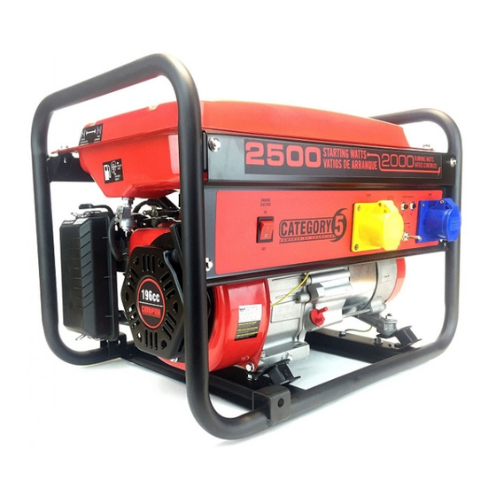
Summary of Contents for Champion CPG2500
- Page 1 OWNER’S MANUAL & OPERATING INSTRUCTIONS Frame Type PORTABLE GENERATOR This manual covers the following models: CPG2500 (EU) / CPG3500 (EU) / CPG4000 E1 (EU) CPG6500 E2 (EU) / CPG 9000 E2 (EU) SAVE THESE INSTRUCTIONS Important Safety Instructions are included in this manual.
-
Page 2: Manual Conventions
Please contact yor local dealer. situation which, if not avoided, could result in death or serious injury. CAUTION Champion Power Equipment Support CAUTION indicates a potentially hazardous situation which, if not avoided, may result in minor or moderate injury. -
Page 3: Safety Rules
SAFETy RULES SAFETy RULES WARNING dANGER dANGER WARNING Generator produces powerful voltage. Fuel and fuel vapors are highly flammable and Rapid retraction of the starter cord will pull hand and Read this manual thoroughly before operating your extremely explosive. arm towards the engine faster than you can let go. generator. - Page 4 ASSEMBLy ASSEMBLy Install the Support Leg Add Engine Oil Add Engine Oil Cont’d. Your generator requires some assembly. This unit ships from our factory without oil. It must be properly serviced 1. Attach the vibration mounts to the support leg with CAUTION NOTE with fuel and oil before operation.
-
Page 5: Operation
ASSEMBLy OPERATION Add Fuel Add Fuel Cont’d. Generator Location Grounding 1. Use clean, fresh, regular unleaded fuel with a Never operate the generator inside any building! (See The generator system ground connects the frame to the NOTE minimum octane rating of 85 and an ethanol content safety warnings section). - Page 6 OPERATION OPERATION Starting the Engine Cont’d. Connecting Electrical Loads Cont’d. do Not Overload Generator Operation at High Altitude Be aware that engine efficiency can reduce and exhaust Capacity NOTE NOTE emissions increase when working at high altitude. Follow these simple steps to calculate the running and Keep choke lever in “Choke”...
-
Page 7: Maintenance And Storage
*To be performed by knowledgeable, experienced owners or To prevent accidental starting, remove and ground spark 7. Attach the spark plug wire to the plug. Champion Power Equipment certified dealers. plug wire before performing any service. Use a damp cloth to clean exterior surfaces of the engine. -
Page 8: Troubleshooting
MAINTENANCE ANd STORAGE TROUBLESHOOTING Storage Charge the Battery Problem Cause Solution The generator should be started at least once every 14 For generators equipped with batteries for electric No fuel Add fuel days and allowed to run for at least 20 minutes. For starting, proper battery maintenance and storage should Generator will not start Faulty spark plug... -
Page 9: Specifications
SPECIFICATIONS SPECIFICATIONS SPECIFICATIONS CPG2500 (EU) CPG3500 (EU) CPG4000 E1 (EU) SPECIFICATIONS CPG6500 E2 (EU) CPG9000 E2 (EU) Gasoline Starting Watts 2300W 2800W 3750W Gasoline Starting Watts 6250W 9375W Gasoline Running Watts 1900W 2500W 3000W Gasoline Running Watts 5000W 7500W Gasoline Starting Amps at 120V 10.45A... -
Page 10: Technical Diagrams
TECHNICAL dIAGRAMS TECHNICAL dIAGRAMS CPG2500 (EU) PARTS dIAGRAM CPG2500 (EU) PARTS LIST CPG2500 No. Part Number Description Qty. No. Part Number Description Qty. 1.5789.0608 Flange Bolt M6 x 8 52 21.110001.00 Shaft, Governor Arm 22.061100.00.2 Cover, Recoil Starter, Black 53 22.123000.01 Ignition Coil, Silicon Rubber 21.061005.00... - Page 11 TECHNICAL dIAGRAMS TECHNICAL dIAGRAMS CPG2500 (EU) PARTS dIAGRAM CPG2500 (EU) PARTS LIST CPG2500 No Part Number Description No Part Number Description CPG2500 Engine 41 2.06.007 Clamp Ø8 x b6 122.190005.00 Rubber, Fore-Cover, B 42 122.070011.04 Fuel Pipe Ø4.5 x Ø8.5 x 140 mm 122.190005.01...
- Page 12 TECHNICAL dIAGRAMS TECHNICAL dIAGRAMS CPG3500 (EU) PARTS dIAGRAM CPG3500 (EU) PARTS LIST CPG3500 No. Part Number Description Qty. No. Part Number Description Qty. 1 1.5789.0608 Flange Bolt M6 x 8 52 21.110001.00 Shaft, Governor Arm 2 22.061100.00.2 Cover, Recoil Starter, Black 53 22.123000.01 Ignition Coil, Silicon Rubber 3 21.061005.00...
- Page 13 TECHNICAL dIAGRAMS TECHNICAL dIAGRAMS CPG3500 (EU) PARTS dIAGRAM CPG3500 (EU) PARTS LIST CPG3500 No Part Number Description No Part Number Description 1 CPG3500 Engine 40 122.072000.01 Fuel Meter Assembly 2 122.190005.00 Rubber, Fore-Cover, B 41 2.06.007 Clamp Ø8 x b6 3 122.190005.01 Rubber, Fore-Cover, A 42 122.070011.04...
- Page 14 TECHNICAL dIAGRAMS TECHNICAL dIAGRAMS CPG4000 E1 (EU) PARTS dIAGRAM CPG4000 E1 (EU) PARTS LIST No. Part Number Description No. Part Number Description 1.5789.0608 Flange Bolt M6 × 8 58 21.110008.00 Pin, Shaft 22.061100.00.2 Cover, Recoil Starter, Black 59 27.111000.20 Control Assembly 21.061005.00 Spring, Recoil Starter 60 25.040013.00...
- Page 15 TECHNICAL dIAGRAMS TECHNICAL dIAGRAMS CPG4000 E1 (EU) PARTS dIAGRAM CPG4000 E1 (EU) PARTS LIST No Part Number Destription No Part Number Destription CPG4000E1-EU Engine 47 122.070300.02 Fuel Filter 122.190005.00 Rubber, Fore-Cover, B 48 122.070100.03 Fuel Tank Cap 122.190005.01 Rubber, Fore-Cover, A 49 62294.2.15.2 Frame 124.191100.00...
- Page 16 TECHNICAL dIAGRAMS TECHNICAL dIAGRAMS CPG6500 E2 (EU) PARTS dIAGRAM CPG6500 E2 (EU) PARTS LIST No Part Number Destription No Part Number Destription 122.070100.03 Fuel Tank Cap 61 152.201200.01 Motor Mount 122.070300.02 Fuel Filter 62 1.5182.10120 Bolt M10 x 120 1.819.0510 Screw M5 x 10 63 253.200016.00 Bush Φ...
- Page 17 TECHNICAL dIAGRAMS TECHNICAL dIAGRAMS CPG6500 E2 (EU) PARTS dIAGRAM CPG6500 E2 (EU) PARTS LIST No. Alias Description Qty. No. Alias Description Qty. 21.061300.00 Handle, Recoil, Soft 62 45.020100.00 Bolt, Cylinder Head Cover 1.5789.0608 Flange Bolt M6 × 8 63 2.08.039 Drain Bolt M10 ×...
- Page 18 TECHNICAL dIAGRAMS TECHNICAL dIAGRAMS CPG9000 E2 (EU) PARTS dIAGRAM CPG9000 E2 (EU) PARTS LIST No. Part Number Description No. Part Number Description 21.061300.00 Handle, Recoil, Soft 62 47.020100.00 Bolt, Cylinder Head Cover 1.5789.0608 Flange Bolt M6 × 8 81.132001.00 Cover, Stepper Motor 46.061100.00.2 Cover, Recoil Starter, Black 64 48.041000.00...
- Page 19 TECHNICAL dIAGRAMS TECHNICAL dIAGRAMS CPG9000 E2 (EU) PARTS dIAGRAM CPG9000 E2 (EU) PARTS LIST No Part Number Destription No Part Number Destription 122.070100.03 Fuel Tank Cap 60 152.201200.01 Motor Mount 122.070300.02 Fuel Filter 61 1.5182.10120 Bolt M10 x 120 1.819.0510 Screw M5 x 10 62 253.200016.00 Bush Φ...
- Page 20 TECHNICAL dIAGRAMS TECHNICAL dIAGRAMS CPG2500 (EU), CPG3500 (EU) & CPG4000 E1 (EU) WIRING dIAGRAM CPG65000 E2 (EU) & CPG 9000 E2 WIRING dIAGRAM...
Need help?
Do you have a question about the CPG2500 and is the answer not in the manual?
Questions and answers