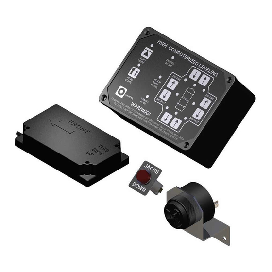
HWH 725 Series Operator's Manual
Computer-controlled
hydraulic leveling system
for trailers
Hide thumbs
Also See for 725 Series:
- Service manual (51 pages) ,
- Operator's manual (27 pages) ,
- Operator's manual (16 pages)
Table of Contents
Advertisement
Quick Links
OPERATOR'S MANUAL
HWH 725 Series, Computer-Controlled
R
Ph: 800/321-3494 (or) 563/724-3396 | Fax: 563/724-3408
AP54598
H H
W
CORPORATION
Hydraulic Leveling System
For Trailers
FEATURING:
Touch Panel Leveling Control
BI-AXIS Hydraulic Leveling
R
Four Single - Acting Jacks
Auxiliary Hand Pump
HWH COMPUTERIZED LEVELING
R
EXCESS
SLOPE
AUTO
LEVEL
INCORRECT
PROCEDURE
AUTO
STORE
CANCEL
CAUTION!
UNDERSTAND OPERATOR'S MANUAL BEFORE USING. BLOCK FRAME AND TIRES
SECURELY BEFORE REMOVING TIRES OR CRAWLING UNDER VEHICLE.
HWH CORPORATION
(On I-80, Exit 267 South)
2096 Moscow Road | Moscow, Iowa 52760
www.hwh.com
R
EXTEND
EXTEND
MANUAL
RETRACT
RETRACT
ML54599/MP04.3561
03DEC14
Advertisement
Table of Contents

Summary of Contents for HWH 725 Series
- Page 1 CORPORATION OPERATOR’S MANUAL HWH 725 Series, Computer-Controlled Hydraulic Leveling System For Trailers FEATURING: Touch Panel Leveling Control BI-AXIS Hydraulic Leveling Four Single - Acting Jacks Auxiliary Hand Pump HWH COMPUTERIZED LEVELING EXCESS SLOPE EXTEND EXTEND AUTO LEVEL INCORRECT MANUAL PROCEDURE...
-
Page 2: How To Obtain Warranty Service
HWH CORPORATION personnel will contact you to the problem quickly. If the dealer has difficulty solving determine whether or not your claim is valid. If it is, HWH the problem, he should immediately contact the Customer CORPORATION will authorize repair or replacement of the Service Department, at HWH CORPORATION. -
Page 3: Control Identification
625/2000 SERIES LEVELING SYSTEM COMPUTER-CONTROL RAISE LEFT SIDE Manual button EXCESS SLOPE Indicator light LOWER FRONT Manual button RAISE FRONT Manual button AUTO LEVEL Indicator light HWH COMPUTERIZED LEVELING LEVEL SENSING Indicator light AUTO LEVEL Button EXCESS (4) yellow SLOPE EXTEND... -
Page 4: Pump Run Time
For cold weather information see "COLD WEATHER OPERATIONS" below. The HWH systems with a computer processor monitor the pump run time and will turn the pump off if the run time exceeds a specified time. This time can vary with different systems. Due to available electronics or system design, the pump run time programs will also vary. -
Page 5: Operating Procedures
OR MORE JACKS ARE EXTENDED TO THE GROUND. If parking on soft ground or asphalt paving, wood blocks or pads must be placed under the jacks. The HWH or OEM supplied master power switch must be on for the leveling system to operate. PREPARATION FOR TRAVEL Before traveling, the red jack warning lights must be off VEHICLE IS EQUIPPED WITH STRAIGHT-ACTING JACKS. - Page 6 OPERATING PROCEDURES INCORRECT PROCEDURE LIGHT NOTE: Early systems have a "NOT IN PARK/BAKE" 1. The "AUTO LEVEL" button will not function unless at light instead of an "INCORRECT PROCEDURE" light. least one front jack is firmly on the ground supporting the These early systems will react to the situations noted weight of the trailer.
- Page 7 Trailer must be unhitched from the tow vehicle before The system will automatically extend the jacks to level the leveling. The HWH front jacks may be used to lift the trailer for vehicle and then extend any remaining jacks for stabilizing.
- Page 8 1. The HWH master switch must be on to hitch 4. Hitch the trailer to the tow vehicle according to the the trailer and store the jacks.
-
Page 9: Manual Leveling
Trailer must be unhitched from the tow vehicle before 3. A lit yellow LEVEL light indicates that the side, end or leveling. The HWH front jacks may be used to lift the trailer corner of the trailer is low. If the rear yellow level light is on, for unhitching. - Page 10 OPERATING PROCEDURES AUXILIARY HAND PUMP OPERATION RELEASE CAM FRONT VIEW END VIEW OPERATING MOTION OPEN CLOSE IF A LARGE VALVE IS USED, OPEN THE VALVE BY REMOVING THE PLASTIC PLUG THEN TURN AUXILIARY THE 1/4" VALVE RELEASE NUT NO MORE THAN HAND PUMP 2 FULL TURNS COUNTER CLOCKWISE.
- Page 11 All major components of the system can be replaced become caked or clogged with mud. This condition may with rebuilt units or can be sent to HWH CORPORATION to hamper the proper operation of the leveling system. This be rebuilt, when the system is out of warranty.
- Page 12 MAINTENANCE PRIMING THE HAND PUMP VALVE RELEASE CAM SHOWN IN SHOWN IN TANK CLOSED OPEN POSITION POSITION OPEN CLOSE EXTEND SOLENOID VALVE HAND PUMP HANDLE JACK CONTROL HYDRAULIC SWITCH CAP END NEUTRAL POSITION EXTEND POSITION OPERATING MOTION TANK DOUBLE-ACTING JACKS (CAP AND ROD END HOSES) HAND PUMP HANDLE...
- Page 13 INSTRUCTION SHEET SENSING UNIT MAINTENANCE/SERVICE REMOTE MOUNTED "POTTED" ELECTRONIC SENSING UNIT SENSING UNIT ACCURACY TOLERANCE The sensing unit has an accuracy tolerance of ± 5.4 inches front to rear and ± 1 inch side to side on a 36 foot vehicle. Typical leveling results will be better. SENSING UNIT ADJUSTMENT / WITH ADJUSTING ENHANCEMENT Level the vehicle by placing a bubble level in the center of the Move the vehicle to an unlevel position and level the...
- Page 14 Valve size and voltage are still factors to be valve. Pushing the cam in the considered when replacing any HWH hydraulic wrong direction could damage solenoid valve. Replace a small style 12 volt the valve.


Need help?
Do you have a question about the 725 Series and is the answer not in the manual?
Questions and answers