Table of Contents
Advertisement
Quick Links
Advertisement
Table of Contents

Related Manuals for Anilam 3000M


Summary of Contents for Anilam 3000M
- Page 1 3000M CNC Motion Setup/Testing Utility www.anilam.com...
-
Page 3: Table Of Contents
AC Systems ............................20 Servo Amplifier Test Board ......................20 Balancing the DSP Board (F6) ..................... 22 ANILAM Amplifier Parameter Files ....................23 Balancing Servo Amplifier Outputs (F6) ..................24 Amplifier Faults ..........................28 Miscellaneous Tests (F9) ......................28 AC and DC Systems ......................... 34 Tuning (F8) ............................ -
Page 5: Introduction
CNC Motion Setup/Testing Utility P/N 70000635C Introduction This section describes how to use the ANILAM Motion Setup/Testing (MST) Utility. The MST provides commands that carry out motion-specific setup and testing in order to tune the Proportional, Integral, and Derivative (PID) filter parameters of a CNC. -
Page 6: Activating The Mst Screen
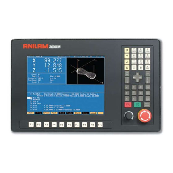
CNC Motion Setup/Testing Utility P/N 70000635C Activating the MST Screen The axis positions displayed correspond to the current position. The Graphics Area displays step responses for the Signal Gain and Tuning functions. Refer to Figure 1 and Table 1. General Status Graphics Area Prompt Area Active Status Codes... -
Page 7: Mst Soft Keys
CNC Motion Setup/Testing Utility P/N 70000635C MST Soft Keys NOTE: Select an active axis before you select an MST command (F1–F9). NOTE: The CNC soft keys are displayed while the MST screen is active. Access MST utility features using the labeled soft keys located beneath the LCD on the console. -
Page 8: Clearing A Prompt Field Or Message (F1)
When you enter the MST Utility and press Balance (F6), Signal Gain (F7), or Tuning (F8), the CNC prompts for the password. Type the appropriate password and press . Refer to 3000M CNC Setup ENTER Utility Manual, P/N 70000499, “Section 1, Password Restricted Parameters.”... -
Page 9: Checking Axis Resolution (F2)
CNC Motion Setup/Testing Utility P/N 70000635C Checking Axis Resolution (F2) Refer to Figure 2. Press ResChk (F2) to calculate the actual resolution for the active axis. In the Graphics Area of the screen, the actual resolution and the resolution in the Setup are displayed for comparison. In addition the screen displays: •... -
Page 10: Starting Reference Mark
CNC Motion Setup/Testing Utility P/N 70000635C Starting Reference Mark This procedure is only necessary during setup of the system and only when the encoder is type **EverTrack 1. Select the axis you want to setup. 2. Press F2 (Resolution Check) to display a pop-up menu with two options: •... -
Page 11: Detecting The Index Pulse (F3)
Press MANUAL (F4) to cancel an active Manual Data Input (MDI) or test command. Activating Manual Data Input Mode (MDI) Press MDI (F5) to activate the MDI Mode. (Refer to the 3000M CNC Programming and Operations Manual for information on MDI programming.) All rights reserved. -
Page 12: Balancing Motion Control Axes
CNC Motion Setup/Testing Utility P/N 70000635C Balancing Motion Control Axes To balance the outputs properly, all connections between the CNC and the servo amplifiers must be complete. Perform all of the adjustments on one axis at a time. Make the adjustments in the following order: 1. -
Page 13: Differential (Ac Systems) And Single-Ended (Dc Systems) Dsp
CNC Motion Setup/Testing Utility P/N 70000635C Differential (AC Systems) and Single-Ended (DC Systems) DSP Board The digital signal processing (DSP) board uses digital input and provides analog output. For the AC systems, the DSP board, P/N 33001102, is differential (see Figure 4). The earliest AC systems were single-ended boards. -
Page 14: Dc Systems
Refer to Figure 6. description NOTE: The test board only works with amplifiers supplied by ANILAM. Figure 6, ANILAM Servo Drive Test Board, P/N 33000102, DC Systems Test Board Installation... -
Page 15: Balancing The Dsp Board (F6)
Balancing the DSP Board (F6) On systems that use an ANILAM Servo Amplifier Board, P/N 33000039 or 33000123 (see Figure 8 (5 LEDS), DC Systems or Figure 9 (1 LED), DC Systems), measurements for this procedure can be made at the J1 input connector with the Servo Drive Test Board, P/N 33000102. - Page 16 5. Press MANUAL (F4) to cancel the test. Output Balance Pot Port 0 Port 1 Port 2 Port 3 33000413 Figure 7, ANILAM DSP Board Balance Pots, P/N 33000413, DC Systems All rights reserved. Subject to change without notice. November 2009...
-
Page 17: Balancing Servo Amplifier Outputs (F6)
HIGH VOLTAGE! SMA7215-1 BRUSHTYPE AMPLIFIER Figure 8, ANILAM Servo Amplifier (5 LEDs), P/N 33000123, DC Systems NOTE: When the amplifier is shipped from the factory, the LOOP GAIN pot is fully counterclockwise (CCW). This is used to shut off uncalibrated amplifiers. When the loop gain is fully CCW, no current is delivered to the motor. -
Page 18: Amplifier Faults
CNC Motion Setup/Testing Utility P/N 70000635C 6. On the ANILAM Servo Amplifier for the axis being adjusted, adjust the balance potentiometer until the MST display is 0000, indicating that the active axis is stationary. – or – Adjust until tach voltage is 0 VDC (±0.001 V), indicating that the active axis is stationary. - Page 19 PULL-UP (LATCHED) OVER TEMP PULL-UP (LATCHED) For LED fault conditions 1 LED servo amplifiers, see Figure 9, ANILAM Servo Amplifier (1 LED), P/N 33000123, DC Systems or Table 5. Table 5, Table of Fault LED Conditions (1 LED) Green Condition 2 FLASHES +/–...
- Page 20 CNC Motion Setup/Testing Utility P/N 70000635C Under Voltage Fault When the +15VDC power supply is below +12VDC, a level that would cause unreliable operation: description The Run LED turns off, a Fault Output is For 5 LED amplifiers: generated, and the amplifier is inhibited. For 1 LED amplifiers: The Green LED turns off, the Red LED is off, a Fault Output is generated, and the amplifier is...
- Page 21 If the inertial load is large, the generated voltage can pump up the DC-Buss. If this fault occurs, you may need a Regen Clamp. Consult ANILAM. Resetting a Fault The fault latch may be reset by pushing the Reset button, activating the Reset input J1–12 or by removing power and allowing the filter...
-
Page 22: Setting The Signal Gain (F7)
If the amplifier should fail, that is, if it should cease to operate with no apparent fault, contact ANILAM. Setting the Signal Gain (F7) Adjust the gains of the ANILAM Servo Amplifier. Refer to Figure 10. Figure 10, Balance Screen, DC Systems NOTE: If ANILAM did not provide the servo amplifiers, follow the guidelines for balancing supplied by the manufacturer. - Page 23 6. Press MANUAL (F4) to cancel the test. Figure 11, Signal Gain (SigGain) Screen, DC Systems If the system is equipped with an ANILAM Servo Amplifier Board, all of the voltage measurements can be made with the Servo Drive Test Board.
-
Page 24: Ac Systems
Servo Amplifier Test Board Each CNC that uses ANILAM AC motors and amplifiers, P/N 33001279, includes a Servo Amplifier Test Board, P/N 33001399. During machine operation, the board provides convenient access to critical signals for alignment and troubleshooting. - Page 25 CNC Motion Setup/Testing Utility P/N 70000635C Test Board Installation IMPORTANT: Press to de-energize servos before installing the STOP test board. 1. Remove the cable attached to J2 of the Servo Amplifier you wish to monitor and connect it to P1 of the test board. 2.
-
Page 26: Balancing The Dsp Board (F6)
P/N 70000635C Balancing the DSP Board (F6) On systems that use an ANILAM Servo Amplifier Board (see Figure 14, Digital Brushless AC Servo Amplifier, P/N 33001279, AC Systems), measurements for this procedure can be made at the J2 input connector with the Servo Amplifier Test Board, (see Figure 12, ANILAM Servo Amplifier Test Board, P/N 33001399, AC Systems). -
Page 27: Anilam Amplifier Parameter Files
Board Balance Pots, P/N 33001102, AC Systems ANILAM Amplifier Parameter Files If using the ANILAM AC Brushless Servo Amplifier (refer to Figure 8, Digital Brushless AC Servo Amplifier, P/N 33001279, AC Systems) make sure that the amplifier's communications cable, P/N 33001389, is connected between the amplifier J1 and the CNC. -
Page 28: Balancing Servo Amplifier Outputs (F6)
2. Select Builder Setup. 3. Select General Axis. 4. Select Digital Amplifier Settings. NOTE: Step 5 values are valid only when you are using ANILAM AC Brushless Digital Servo Amplifiers. If using amplifiers not provided by ANILAM, follow the manufacturer's guidelines for balancing, signal gain setting, and overall adjustments. - Page 29 CNC Motion Setup/Testing Utility P/N 70000635C J7 J1 ACU-RITE COMPANIES INC. AMPLIFIERAC Figure 14, Digital Brushless AC Servo Amplifier, P/N 33001279, AC Systems All rights reserved. Subject to change without notice. November 2009...
- Page 30 CNC Motion Setup/Testing Utility P/N 70000635C Setting the Balance (F6) Install the Servo Amplifier Communications Cable, P/N 33001389, between the amplifier's J1 connector and the CNC's RS-232 port. 1. At the Software Options menu, select Motion Setup/Testing. 2. Press and release the button.
- Page 31 3000SIGGAIN Figure 16, Signal Gain Test Screen, AC Systems IMPORTANT: Steps 9–13 apply only to ANILAM brushless AC amplifiers. For other amplifiers, refer to the manufactures guidelines to set the signal gain in the amplifier.
-
Page 32: Amplifier Faults
Press Misc (F9) to display a pop-up menu with eight (8) selections. The tests marked ** on the right apply only for systems equipped with an ANILAM AC Amplifier (P/N 33001279). These tests can only be activated with the Servo Amplifier Test Board installed. See “Servo Amplifier Test Board.”... - Page 33 CNC Motion Setup/Testing Utility P/N 70000635C CanBus Test Refer to Figure 17. Press Misc (F9) to display the Miscellaneous Test pop-up window. Select CanBus Test to display the graphics a rea and to troubleshoot the st atus of all inputs and outputs for the nodes. CNC Ver 3.70H DSP Ver 0.00C Line 1...
- Page 34 CNC Motion Setup/Testing Utility P/N 70000635C . Line 5 indicates: • The status of the ten inputs of each node. • The status of the six outputs of each node. • Subsequent lines indicate the I/O status of any additional nodes.
- Page 35 CNC Motion Setup/Testing Utility P/N 70000635C The following graphic s display two possible results: • Refer to Figure 18. Axes optimally tuned repor ted a retract lag of 51 microns. seconds Figure 18, Axes Opti mally Tuned Screen • Refer to Figure 19. Z-axis without being optimally tuned (default gains).
- Page 36 P/N 70000635C Save Amp Se ttings This feature is only for systems equipped with an ANILAM AC Amplifier (P/N 33001279) and with the Servo Amplifier Communications Cable, P/N 33001389, connected. Refer to “Setting the Balance (F6)” and “Setting the Signal Gain (F7).”...
- Page 37 CNC Motion Setup/Testing Utility P/N 70000635C Reset Amplifier This feature is only for systems equipped with an ANILAM AC Amplifier (P/N 33001279) and with the Servo Amplifier Communications Cable, P/N 33001389, connected. This resets the AC amplifier. BackUp Amp Settings...
-
Page 38: Ac And Dc Systems
Tuning (F8) Saving Final Values Exiting the MST Screen (F1 Tuning (F8) NOTE: ANILAM recommends that you set signal gain and balance the servo amplifier, as discussed in previous text, before tuning. CAUTION: Most machines will operate correctly with the default filter parameters. - Page 39 CNC Motion Setup/Testing Utility P/N 70000635C If y ou have selected Kd (derivative gain), the CNC begins by measuring derivative sampling time (Ds). It measures the time between 10 % and 90% of the final velocity (rise time) and divides it by five. A porti on of this time is determine d to be the Ds.
- Page 40 CNC Motion Setup/Testing Utility P/N 70000635C Table 10, Tuning Functions Values Parameter Function Determines amount of overshoot the CNC will seek Kp Overshoot % before ending the Kp cycle. 1% to 5% is a normal overshoot range for this test. If detected oversho exceeds the entered OvSht%, the cycle e nds.
-
Page 41: Saving Final Values
NOTE: ANILAM recommends that you back up your configuration file before you save tuning results. This will enable the filter parameters to be recovered if necessary. Refer to 3000M CNC Setup Utility Manual, P/N 70000499, for details on backing-up and restoring setup parameters. - Page 43 CNC Motion Setup/Testing Utility P/N 70000635B - Index + F7), AC systems, 32 MST screen, 2 CTRL 3000M CNC Programming and active digital amplifier, to set, AC systems, 24 Operations Manual, referenced, 1, 7 active status codes area, 3000M CNC Setup Utility...
- Page 44 CNC Motion Setup/Testing Utility P/N 70000635B - Index back up, 37 backup file, miscellaneous tests, description, AC systems, 33 starting mark, entry, 6 backup, restore from, amp parameters, AC systems, 33 balance DC systems adjustment (mV), setting, AC systems, 24 amplifier faults, 14 test screen, illustration, AC systems, 26 Balance Screen, illustration, 18...
- Page 45 CNC Motion Setup/Testing Utility P/N 70000635B - Index HS/ECB fault, description, DC systems, digital signal processing. See disclaimer, 1 LS/ECB fault, description, DC systems, Ds, derivative sampling time, 35 DSP, defined, 9 over temp fault, description, DC systems, board over voltage fault, description, DC balance pots, illustration, AC systems, 23 balance pots, illustration, DC systems, 12 systems, 17...
- Page 46 Breaker. See LS/ECB DC systems, 17 LS/ECB fault, causes listed, DC systems, 16 P/N 70000499, 3000M CNC Setup Utility Manual, Manual (F4), 3, 7 referenced, 4, 37 Manual (F4), DC systems, 19 password, entering, 4 Manual Data Input.
- Page 47 CNC Motion Setup/Testing Utility P/N 70000635B - Index single-ended DSP rotary encoders, index pulse, 7 board, illustration, DC systems, 9 soft keys area, illustration, 2 soft keys, MST, listed, 3 save amp settings Software Options screen, 1 description, AC systems, 32 spindle axis, keypad key, select, AC systems, 27 illustration, 4...
-
Page 48: Index
CNC Motion Setup/Testing Utility P/N 70000635B - Index Z-axis, keypad key, illustration, 4 Index-6 All rights reserved. Subject to change without notice. November 2009... - Page 50 HEIDENHAIN CORPORATION 333 East State Parkway Schaumburg, IL 60173-5337 USA +1 (847) 490-1191 +1 (847) 490-3931 E-Mail: info@heidenhain.com www.heidenhain.com 70000635C · 1 · 11/2009 · Printed in USA...
Need help?
Do you have a question about the 3000M and is the answer not in the manual?
Questions and answers