Sign In
Upload
Manuals
Brands
Anilam Manuals
Controller
3000M
User Manuals: Anilam 3000M CNC Control System
Manuals and User Guides for Anilam 3000M CNC Control System. We have
3
Anilam 3000M CNC Control System manuals available for free PDF download: Training Manual, Utility Manual, Manual
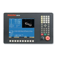
Anilam 3000M Utility Manual (126 pages)
CNC
Brand:
Anilam
| Category:
Controller
| Size: 1 MB
Table of Contents
Table of Contents
3
Section 1 - Machine Setup Introduction
7
Effectivity Notation
7
Software Version Information
7
Navigating through the Setup Utility
8
Keypad Keys
8
Specifying an Axis
9
Entering Parameters
9
Highlighting Menu Options
9
Exiting a Screen
9
Password Restricted Parameters
9
Saving Changes to Setup Parameters
10
Setting Parameters in Setup Utility
10
Accessing Setup Utility Menus
10
Overview of Main Parameter Categories
11
Units of Measurement
11
Section 2 - Builder Setup
12
Setting Axis Resolution Parameters
12
Setting Axes for Encoder Type
12
Setting the Display Resolution
12
Setting the Linear Encoder Resolution
13
Setting Line Count for Rotary Encoder
14
Setting Ballscrew Pitch for the Rotary Encoder
14
Setting the Ratio between the Ballscrew Pulley and the Motor/Encoder Pulley
14
Setting the Starting Mark
15
Setting Linear Correction Compensation
16
Setting In-Position Tolerance
17
Setting Continuous Path
17
Setting Default Rapidrate
18
Setting Axis Default Feedrate
18
Setting Software Limits
19
Enabling Vector Limits
20
Setting Encoder Phases to Correct Axis Direction Displayed
20
Setting Backlash Compensation
21
Setting Ballscrew Compensation
22
Setting Number of Segments
22
Setting Table Entries
23
Setting Offset and Zero Cross Parameters
24
Setting Segment Length
25
Activating Ballscrew Compensation
25
Using the Automatic File Loader
26
File Loader Error Messages
29
Setting Axis Ports
30
Setting Feed, Rapid, and No-Motion Filter Parameters
30
Setting Position Error Check Parameters
33
Setting Amplifier Tuning Rapids
34
Setting Digital Amplifier
34
Setting Invert DAC Output
35
U Axis Setup
35
Setting the Spindle Axis
36
Setting Spindle Output
36
Setting Spindle Gear Ranges
37
M40-M41 Ratio (Spindle Pulley)
38
M40-M41 Ratio (Motor Pulley)
38
Setting the Number of Lines on the Spindle Encoder
38
Setting Spindle RPM Display
39
Setting Stop/Start Spindle When Hold/Start Is Pressed
39
Setting Stop Program and Spindle on Gear Range Error
39
Setting Encoder Mounted on Motor
39
Setting Spindle Zero Speed RPM Tolerance
40
Setting Spindle at Speed Percent
40
Setting Z Axis Type
40
Setting Basic I/O Interface
40
Activating the I/O Interface
41
Output Function Setup
42
Configuring Output Ports
43
Setting up DSP Nodes
44
Assigning Output Ports to M-Functions
44
Assigning Input Ports to Input Functions
46
Selecting Automatic Gear for DAC Output
46
CNC Input Functions
47
Setting Finish Pulse Timeout
49
Setting Vector Limit Inputs
50
Vector/Home Limit Switch Connections
51
I/O Settings for Factory-Assembled M-Function Hardware
52
Programmable I/O Interface Setup
52
Handwheel/Dro Setup
52
Handwheel Parameters
53
DRO Parameters
54
Tool Management Setup
56
Default Tool Table File
56
Activation Options
56
Manual Tool Change Operation
57
Activating Tool Length Offset
57
Setting Output Signal to Default
57
Setting Default Spindle Orientation Angle
58
Setting Spindle Orientation RPM
58
Setting Spindle Orientation in Position (Counts)
58
Stopping Program Run on Tool Commands
59
Setting the Use Tool Change Macro
59
Setting the Tool Change Macro Program
59
Setting the Default Tool-Table File
60
Setting the Force Spindle off During Tool Change
60
Setting the Restore TLO after Power-Up or Home
60
Setting the Send Tflag When T0 Programmed on Fixed TC
60
Miscellaneous Setup Parameters
61
Setting Maximum Programmed Linear Axis Feedrate
61
Setting Dry Run Feedrate
61
Setting Default Linear Axis Jog Feedrate and Jog Rapidrate
62
Maximum Programmed Rotary Axis Feedrate
62
Rotary Axis Dry Run Feedrate
62
Rotary Axis Jog Feedrate
63
Servo up Delay
63
Automatic Feedrate Override on Arcs
63
Feed and Rapid Accel/Decel (Ms)
64
Check DSP Integrity
64
Servo Loop Sample Time (Ms)
64
Interpolator Rate Factor
65
Acceleration Ramp Type
65
Ramp Z Axis During Rigidtap
65
Enable Velocity Look Ahead
65
Monitor Setting
66
Display Resolution
66
CNC Startup Mode
66
Show Introduction Screen
66
User Definable Variables
67
Tool Changer Macro Example
67
Mcode for Macro Call #1 - #10
68
Macro Called for Mcode #1 - #10
68
Homing the Axes
69
Setting Homing Sequence
69
Direction of Travel for the Homing Feature
70
Setting Homing Speed
71
Setting Home Preset Values
71
Builder Text
72
Enabling Builder Text
72
Editing Error Messages
73
Editing Warning Messages
74
Editing Soft Key Inputs
75
Languages
76
Software Updates
76
Direct Numeric Control
77
Selecting a DNC Execution Mode
77
Setting the Buffer Size
78
Enabling/Disabling Toolcomp and Cornerrad
78
Setting DNC Mode to Hold Execution of Program until You Press Start
79
Security
79
Probing
80
Setting the Spindle Probe Type
80
Setting the Nominal Probe Stylus Diameter
80
Setting the Maximum Stroke from Home for First Pick
80
Setting the RPM for Calibration and Tool Measurement
80
Setting the Probe Orientation
81
Setting the Z First Pick, FAST Feedrate
81
Setting the Z First Pick, MEDIUM Feedrate
81
Setting the Z Final Pick, SLOW Feedrate
82
Setting the Z Retract Amount
82
Setting the XY Retract Amount
82
Setting the Z Start Position
82
Setting the Diameter of Tool Probe Gauge
83
Setting the Positioning Feedrate Normally
83
Setting the First Touch Feedrate
83
Setting the Nominal Probe Stylus Ball Radius
83
Setting the Diameter of Spindle Probe Gauge
84
Setting the Probe Logic
84
Section 3 - Operator Setup
85
Control Software Parameters
85
Compensation Cutoff Angle
86
Communications Parameters
89
Simulated Draw Mode Setup Parameters
90
Edit Mode Setup Parameters
92
Program Directory Parameters
93
Display Settings
94
Printer Settings
94
Section 4 - Configuration Utilities
95
Save Configuration
95
Copy Configuration
95
Restore from Copy
96
Restore from Backup
96
Compare Configuration
96
Print Configuration
97
Section 5 - Fine-Tuning Systems with Linear Encoders
98
Map 5
99
Map 12
101
Map 13
102
Map 14
103
Map 15
104
Advertisement
Anilam 3000M Training Manual (132 pages)
3 Axis CNC Control
Brand:
Anilam
| Category:
Industrial Equipment
| Size: 1 MB
Table of Contents
Navigation Instructions
2
Function Keys
9
Program Page
12
Original Size
66
Anilam 3000M Manual (50 pages)
Motion Setup/Testing Utility
Brand:
Anilam
| Category:
Control Systems
| Size: 1 MB
Table of Contents
Table of Contents
3
Introduction
5
Accessing the MST Utility
5
Activating the MST Screen
6
MST Soft Keys
7
Clearing a Prompt Field or Message (F1)
8
Selecting an Axis
8
Entering a Password
8
Checking Axis Resolution (F2)
9
Starting Reference Mark
10
Detecting the Index Pulse (F3)
11
Canceling the Active MDI or Test Command
11
Activating Manual Data Input Mode (MDI)
11
Balancing Motion Control Axes
12
Differential (AC Systems) and Single-Ended (DC Systems) DSP
13
Board
13
DC Systems
14
Servo Drive Test Board
14
Balancing the DSP Board (F6)
15
Balancing Servo Amplifier Outputs (F6)
17
Amplifier Faults
18
Setting the Signal Gain (F7)
22
AC Systems
24
Servo Amplifier Test Board
24
Balancing the DSP Board (F6)
26
ANILAM Amplifier Parameter Files
27
Balancing Servo Amplifier Outputs (F6)
28
Amplifier Faults
32
Miscellaneous Tests (F9)
32
AC and DC Systems
38
Tuning (F8)
38
Saving Final Values
41
Exiting the MST Screen (F10)
41
Index
48
Advertisement
Advertisement
Related Products
Anilam 3300M
Anilam 4200T CNC
Anilam 5000M CNC
Anilam 6000M
Anilam Categories
Control Systems
Controller
Digital readouts
Industrial Equipment
Music Mixer
More Anilam Manuals
Login
Sign In
OR
Sign in with Facebook
Sign in with Google
Upload manual
Upload from disk
Upload from URL