
Related Manuals for Anilam 3000M


Summary of Contents for Anilam 3000M
- Page 1 ANILAM 3000M 3 Axis Training Guide...
-
Page 2: Navigation Instructions
Navigation Instructions Bookmarks Follow the bookmarks at the left side of the page to navigate to desired topic Click plus and minus symbols to expand and compress menu display... - Page 3 3000M CNC Control Training Guide...
- Page 4 Turning the Control ON After the control has been turned ON press F10 to continue. Then press to select next page Select...
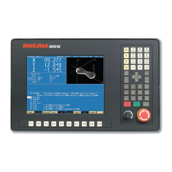
- Page 5 Main Areas of the Display Machine Position from Home Machine Status Programmed Position Auxiliary Functions Message Area Information Program & Tool information...
- Page 6 Areas of Main Screen Program Name Halted or Running Mode of machine Manual , Single Step or Auto Type of movement Rapid or Feed Condition of machine Type of move abs/inc Units Inch/MM Number of loops Type of Manual movement remaining to be done Rapid,Feed,100,10 or 1 Time left...
- Page 7 Keyboard Keyboard Keyboard Keyboard 9 and Plane key 7 and Unit XY,XZ & YZ. Inch/MM. 4 and Feed key 8 and Dwell key 5 and Tool mount 6 and Mcode key 3 and Arc key Axis keys 2 and Line key 1 and Rapid key .
- Page 8 Along with the above we have “Hot Keys” Accesses Rapid menus. Rapid Accesses Line menus. Line Accesses Arc menus. Input feedrate. Feed Tool mount. Tool Mcode inputs. MCode Inch/MM Unit Dwell in seconds Dwell Changes from XY,XZ or YZ. Plane If * put in front of line in program ignores that line.
-
Page 9: Function Keys
Function Keys The Function (or F keys) activate the Mode shown directly above on the Display screen. The meaning of F keys change, depending upon what Mode of operation is selected. An example of how F keys is shown above,this is how it would change when going from Manual to in Single Step or Auto. - Page 10 Display last 8 messages that have appeared Message Program Page at which program files are displayed Go to EDIT from Manual Edit Manual mode of operation Manual S.Step Single step mode of operation Auto mode of operation Auto M D I Manual data input,allow operation without writing a program Not used Tool...
- Page 11 F1 Message Page To enter message page press Message This is how the messages will appear on the screen . When control is turned off the messages will be erased. This is useful to tech’s when trouble shooting problems on the control...
-
Page 12: Program Page
Program Page To enter page Press F2 Program Not used Create This where new program names are type in. Delete an existing program. Delete Edit Programs are written and changed. List Allows you to look at program but no Editing . Picks program to be run. - Page 13 Create When ASCII is pressed, this how the soft keys will look and a table will appear as show below Using the arrow keys pick the letters then press the enter key.When complete press ASCII again and press enter, this will put program into the list of programs with .M extension and highlight will be on program that was just created.
- Page 14 Edit When is press, the screen appear as shown below. Edit Pressing allows user to look you to look at program only. List...
- Page 15 Select Program that is highlighted and then selected will shows up in this area. A program may be edited without being selected , but not run in Single step or auto.
- Page 16 Display Show all in program files but show size of Normal screen only show .m files page program,date and time written Show only .m files but show size of program, Press display one time it will change to date and time written display all files in directory...
- Page 17 F keys there different functions. First press type in a program name or number. Create Edit High light will be on program just created press Teach Let user move machine around and record positions. Draws program be running to see that it is correct. Draw Drill Access to drilling canned cycles.
- Page 18 Press Tool This will bring up the Tool Page. Area #! Area #2 Area #3 Area#4 Area #5 Area #11 Area #9 Area #10 Area #6 Area #7 Area #8 Area #1 Machine position relative to part Zero. Area #2 Machine position relative to machine zero.
- Page 19 Go to FIXTURE OFFSET page OFFSET Not used Clear highlighted line info. ClrLine Search for a tool. Find PgUp Page up PgDn Page down Not used Calib Z Calibrate Z axis offset. Not used Exit to edit page when entered from edit page. Exit If entered from MANUAL page Exit...
- Page 20 OFFSET Press this will take you to offset page. All entries are taken from Machine Home. Entries may be entered manually or by using CalibX or CalibY. When doing manual input , select axis you wise to enter a value , by pressing that axis key and input number require press ENTER.
- Page 21 Enter adjustment value is an added feature that allows altering of existing values in the tool page or fixture offsets display. Use the ABS/INC Key to activate this feature. Example: Altering tool diameter using Enter adjustment value. * Asterisk highlights the selected value. Example: Altering fixture offsets using Enter axis and adjustment value...
- Page 22 3000M CNC Control Lines and Arcs...
- Page 23 Lines and Arcs Lines and arcs can be access in two ways . 1. Using hot keys. Accesses Rapid menus. Rapid Accesses Line menus. Line Accesses Arc menus. 2.Using soft keys Mill Press Rapid Press More... Press...
- Page 24 Screen will now show 6 icons , these apply to both rapid and line moves. Line and Rapid are the same with one exception CornerRad and feed are not in rapid. 1. Enter coordinates in any or all axis.
- Page 25 2. Using Radius and Angle from current position. 3. X axis move is an Absolute dimension, the Angle relative to Zero (three O’clock). Below it is Y axis and Angle.
- Page 26 4.Axis and Angle If programming absolute X or Y dimension is from Part 0 and radius is from current position. If programming incremental X or Y dimension and radius are from current position.
- Page 27 Mill More... The icon below are for arcs. Tool must be at start point of arc before it is programmed. Arc may be cut in any plane but must selected, default is XY.
- Page 28 1.This is the default arc , End points for 2 axis and radius. Direction is changed by pressing +/- key. If programming an arc over 180 deg the radius is entered as a minus (-) value. 2. With this arc it is possible to mill a thread . Enter X Y and Z end point , X Y center point and Number of Revolutions.
- Page 29 3.Center and angle Programming absolute angle is from 3 o’clock position direction is also critical. The above lines of program starts at 45 deg’s the center is X0, Y0 and go to 90 deg’s in a counter clockwise direction, it will go to 12 o’clock, actually only moving 45 deg’s.
- Page 30 Not used. Used to recall enters from calculator , will cover later. Recall Not used. More . . . Used with Rapid , Line and Arc as shown previously . Not used. Not used. Calc Calculator this will be cover later. Not used.
- Page 31 3000M CNC Control Canned cycles...
- Page 32 Drill Canned Cycles & Patterns 1. Basic Rapid to Z start, Feed to Z depth, Rapid to Z return. 2. Pecking Rapid to Z start, Feed to peck, Rapid to Z start, Rapid to last peck, Repeat peck cycle to Z depth, Rapid to Z return.
- Page 33 Peck Drilling ZDepth Feed Z axis to depth. StartHgt Rapid start of Z axis before feed to depth. ReturnHgt Rapid return of Z axis from Z depth (Optional). Peck Peck increment “ + Value” Feed Feed rate “ Inches per minute” (Optional). Tool# Activate new tool (Optional).
- Page 34 Chip Break Cycle ZDepth Feed Z axis to depth. StartHgt Rapid start of Z axis before feed to depth. ReturnHgt Rapid return of Z axis from Z depth (Optional). FirstPeck First unaltered pecking increment “ + Value”. PeckDecr Decrement first peck each cycle “ + Value”. MinPeck First peck altered to minimum value “...
- Page 35 Pattern Drill X start location (Optional). Y start location (Optional). #XHoles Number of holes on X axis including starting hole. #YHoles Number of holes on Y axis including starting hole. XInc Incremental distance between all holes on X axis ”Use – or + values for direction”. YInc Incremental distance between all holes on Y axis ”Use –...
- Page 36 Thread Milling Cycle WARNING: The first move in this cycle is a rapid move to the center of the thread before moving the Z-axis. Make sure the tool is properly located before calling up this cycle. Thread Milling Cycle simplifies the programming required to mill a thread.
- Page 37 3. Enter the following required values and settings in the Thread Mill entry fields: XCenter Absolute X coordinate of the center of the thread. If no coordinate is entered, the CNC puts the center of thread as the current tool position.
- Page 38 ArcInRad Size of radius arcing into start of thread. (Optional) NOTE: If ArcInRad is a positive value or not set and the thread is “inside,” the cycle will always return to the center between passes. If ArcInRad is a negative value, the cutter will move to the start or end point that is closest to the center if inside thread, and farthest away from center if outside thread.
- Page 39 • The Z axis will feed down to the start cut position ZStart. This could be above or below the Z position specified in the ZFinish position. • Depending on what is in the ArcInRad parameter, the tool will arc into the first cut position. •...
- Page 40 Sample Thread Program This program will cut an 8 TPI thread starting at 0.1 above the hole. The major diameter of the thread is 1 inch. It will take 2 roughing cuts and 1 finish cut with a 0.625 cutter. Dim Abs Tool# 1 Rapid...
- Page 41 Pocketing Canned Cycles Note The pockets marked with * all have cutter compensation built into them, so all dimension are as show on print. 1.Face. Cleans large area with one line of information. 2.Rectangular profile.* Cleans inside or outside of a rectangle. 3.Circular profile.* Clean inside or outside of a circle.
- Page 42 Rectangular profile XCenter. Center of profile along X axis. Optional YCenter. Center of profile along Y axis Optional StartHgt. Height Above surface to be cut. Length. Length of pocket. Width. Width of pocket. ZDepth. Absolute depth of pocket. Side. Inside or Outside. Ramp.
- Page 43 Rectangular Pocket Xcenter. Center of pocket X axis. Optional Ycenter. Center of pocket Y axis. Optional StartHgt. Must be .1” or 2mm above surface to be cut. Length. Actual length of pocket. Width. Actual width of pocket. Zdepth. Absolute distance to bottom of pocket. Direction.
- Page 44 Frame Pocket Xcenter Center of pocket X axis. Optional Ycenter Center of pocket Y axis. Optional StartHgt Must be .1” or 2mm above surface to be cut. IslandLen Actual length of center island. IslandWid Actual width of center island. Zdepth Absolute distance to bottom of pocket.
- Page 45 Irregular Pocket Sub# # of profile subroutine. Start position of profile X axis. Optional Start position of profile Y axis. Optional StartHgt Start height .1” or 2mm above surface to be cut. Zdepth Z depth of pocket absolute. Angle Angle of first cut. Optional Xstart Position of X axis before moving to start of profile.
- Page 46 Mold Rotation StartAngle Angle at which rotation is going to start. EndAngle Angle at which rotation is going to end. Cycles Number of passes , one cycle is a pass in each direction. FwdSub Number of first subroutine. RevSub Number of second subroutine. AxisRot Axis around which rotation is going take place.
- Page 47 Pockets with Islands This cycle allows islands in irregular pockets. The main pocket must the lowest subroutine number. Normally, this would be one (1). Pockets with Islands can be programmed using: • DXF (see “Section 15, Using DXF for Pockets with Islands (G162)”) •...
- Page 48 In Table 5-1 Island # 4 (FourthIsl) has a – (minus) in front of it, this is because the comp needs to be on the inside, as it is a pocket inside of an island. Table 5-1 Pockets with Islands Subroutines Programming Example Unit Inch Dim Abs...
- Page 49 Line X 13.0000 Line Y 8.0000 EndSub Sub 5 Rapid X 8.0000 Y 17.0000 Feed 50.0000 Arc Ccw X 12.0000 Y 17.0000 Radius 2.0000 Arc Ccw X 8.0000 Y 17.0000 Radius 2.0000 EndSub Sub 6 Rapid X 14.0000 Y 9.0000 Line X 15.0000 Arc Ccw...
- Page 50 There are two more canned cycles , to get to these press Mill soft key. Soft key will change as above press a pop-up will appear as below. More Ellipse and spiral both must be programmed incrementally . Put height light on Ellipse press screen will change as below.
- Page 51 Direction Direction of cut CW or CCW. Distance from Start to End X axis of Ellipse. Distance from Start to End Y axis of Ellipse. Distance from Start to End Z axis of Ellipse. Xcenter Distance from Start to Center X axis of Ellipse. Ycenter Distance from Start to Center Y axis of Ellipse.
- Page 52 Direction Direction of Spiral Clockwise or Counter Clockwise. Distance from Start to End X axis . Distance from Start to End Y axis . Distance from Start to End Z axis. Xcenter Distance from Start to Center X. Ycenter Distance from Start to Center Y. Revs Number of Revolutions.
- Page 53 Engraving, Repeat, and Mill Cycles This section describes operation of three new cycles: Engraving Cycle Repeat Cycle Mill Cycle Engraving Cycle The Engraving cycle provides a quick and easy way to engrave part numbers, legends, or any alpha/numeric inscription. The usual type of cutter is a sharp point or center-drill type tool.
- Page 54 [Optional] MirrorY Mirrors all Y moves. Set by using minus key (-) while in this field. [Optional] Feed Feedrate used while engraving. Default is current feedrate. [Optional] Tool# Active Tool [Optional] Used only on 3000M controls – not on 6000M...
- Page 56 Sample Engraving Cycle Program Dim Abs Unit Inch Rapid X 0.00000 Y 0.00000 Tool# 1 Rapid X 1.00000 Y 1.00000 Rapid Z 0.10000 Engrave Text "ABCD" StartHgt 0.0100 ZDepth -0.0100 Height 0.5000 Rapid Z 1.00000 Rapid X 0.00000 Y 0.00000 EndMain This program will rapid to X1.0 Y1.0.
- Page 57 2. Complete the entry fields (refer to Table 5-3), and press ENTER Table 5-3, Repeat Cycle Entry Fields Entry Field Description Repeat Type the block number you want to begin repeating. [Required] Thru Type the block number you want to end the repeat. [Required] 3.
- Page 58 Mill Cycle The Mill cycle is intended for contour milling operations. Cutter compensation, Z pecking, Z finish stock, RoughFeed, and FinishFeed are supported. The cycle will rapid to the XY start point (compensated, if comp is on) rapid to the start height and then feed to the Zdepth or DepthCut using the Zfeed.
- Page 59 Amount of stock to take for last Z peck. [Optional] FinFeed Feedrate used for FinStock. [Optional] Tool # Active Tool. [Optional] Used only on 3000M controls – not on 6000M Sample Mill Cycle Program Dim Abs Unit Inch Rapid X 0.00000 Y 0.00000...
- Page 60 3000M Rotate / Mirror / Scale...
- Page 61 To get to RMS , when in edit press Press Sub# Number of subroutine to Rotated, Mirrored or Scaled #Loops Number of time to repeat Rotation. StartAngle Start angle of rotation. Angle Angle between Rotations. Xcenter Center of Rotation X axis. Ycenter Center of Rotation Y axis.
- Page 62 Rotation When using RMS a subroutine must be writen. Above are the entries in canned cycle. Save Press This how the program will look, line #4 is the rotation cycle. Note all moves including Z’s are in the subroutine. This is how it look in graphics.
- Page 63 In the case only one rotation is required the entry would be as below. Note only 4 entries Sub , StartAngle , X & Y centers. Program line would look as below. Graphics of the single rotation appears below.
- Page 64 Mirror Mirrror also requires a Subroutine to be writen. Put hight light on axis to be mirrored press +/- key to turn on. Line #4 as programmed Line #6 mirror imaged As programmed Mirrored X & Y...
- Page 65 The following program shows the part cut in all four Quadrants. The one thing to keep in mind when using mirror image is that when using cutter compensation the cut direction will change in the diagonal quadrants. As programmed Mirror X Mirror X&Y Mirror Y...
-
Page 66: Original Size
Scale Scale allow programmer to change the size of the part. One thing to remember is that if radii are involved both axis must be scale the same amount. Line #5 original line #6 scaled x2 Scaled x2 Original size... - Page 69 3000M Cut / Copy / Paste...
- Page 70 This section will deal will copying, pasting and other editting features. Copying portions of programs and inserting then into another program. Program Press Create Press Type program name 012. Edit Press Start writing program as above.
- Page 71 Misc Softkeys will appear as above press More…. Press This pop-up window will come up curser down to Open Program. Press Enter name of program number (0123) that you need to copy from press...
- Page 72 New program will now be on screen. More…. Misc Press Press Press on mark. Put high light on first block be to be copied. Press Use arrow keys to mark all blocks required.
- Page 73 More…. Press Press Enter original program number. High light block #4 (End of Program.) More…. Press...
- Page 74 High light Paste press It inserted lines 4 - 8 into proggram #012. Cut is used remove a section of program once it’s marked. Delete will cut pieces of marked program out.
- Page 75 3000M Calculators...
- Page 76 Edit To get to calculator Press Calc Press Box will appear as below. 1.Pocket. 2. Rightangled triangle. 3. Geometery The box with the hight light around it is the active one. In this case it is the left hand box.
- Page 77 Press screen will appear as below. Plus Minus Multiply Divide Brackets Functions Clear Store Exit...
- Page 78 Func When is press the listed functions are available. These funtions allow you to do trig and math problems.
- Page 79 Hight light center icon , this is rightangled triangle calculator. Press screen will appear as below. Find Enter any 2 sides or a side and an angle press all of the blanks will be filled in , the calculated dimensions will have an asterisk behind them. They can be stored and recalled later into a program.
- Page 80 Hight light right icon , this is the geometry calculator. Press screen will appear as below. This calculator allows us to generate lines,points and circles. We will need to gererate poins at all intersections , as points are the only items we can recall.
- Page 81 The soft keys will appear as below. HIDE Allow you change from calculator to program mode. DISPLAY See below GEOMETR See below EXIT Exit Geometry calculator. Fit to screen. Zoom in to an area on the screen. Redraw at current size. Halfs the screen size.
- Page 82 Point Definitions Point defined by co-ordinates X and Y Point at a position X & Y from a previously defined point Point at a distance R and an angle A from a previously defined point Point at the centre of a circle Point at an INTERSECTION between 2 elements Point previously defined Line Definitions...
- Page 83 From the drawing below we are going to get all points required to program an irregular pocket. 6.25” R 2.00 X0 Y0 R 4.00 3.75 R 1.8...
- Page 84 The first element to find is the 4.00 circle Edit Calc Press press The third icon is hight lighted press Press...
- Page 85 When is pressed screen will ask for Radius value, in this case 4., zero’s not required. Press It will now ask for a center definition and top left icon is hight lighted. This is one to use in this case. Press...
- Page 86 It will now ask for an X value, in this case it 0 ,so press It will now ask for an Y value, in this case it 0 ,so press The circle will now appear on the screen, if it show as a dot on screen DISPLAY press select FIT press...
- Page 87 The 2” circle will now be entered. Use the same icon as before. Radius 2” use same center icon X 0 and Y4.25 press ENTER. Second circle will now appear on screen, it may be necessary to fit again. Note:The first circle has a 1 beside it and second has a 2. Each element will be numbered.
- Page 88 There is now enough geometry to find all the intersect required to program this part. It is only possible to recall points into a program, so the thing that has to be done is find the points at all intersects using the icon below. Required intersects The first intersect is between element 1 &...
- Page 89 Select the icon with a line going through a circle. Press select first element #1 select second #2, as there are two intersects there is a choice of 1 or 2 in this case the desired one is #1. There is now an element #4 which is the intersect between #! And #2.
- Page 90 Using same icon,find intersects between ! & 3, two places and 1 & 2 right side. Above is completed geometry, with all intersections marked with a point.
- Page 91 Writing program to pocket this shape. Below is how main program would look, the next thing to do is write the profile of part to be pocketed. Dim Abs * Absolute dimensioning Rapid Z 0.0000 Tool# 0 *Clear all offsets Tool# 1 * Call tool #1 Pocket...
- Page 92 Press Recall Point Required #4 The letter C at end of line means circle center and P means point. Move high light down to #4. Using key press press Dimensions for X & Y will be input into program, move cruser down to Radius enter 2”...
- Page 93 The same can now be done with points 5,6 & 7, the last point will be the same as the first X0 Y6.26 end point of 2” arc. The following is how the program should look when complete. Dim Abs Rapid Z 0.0000 Tool# 0 Tool# 1...
- Page 94 If all looks good in draw part is ready to cut. Press Exit Exit Press...
- Page 95 3000M Program Example...
- Page 96 Typical starting program...
- Page 97 Edit Press to enter editor. Dimension can be entered into by F2 Rapid , F3 feed or Modal. Teach Draw Simulation draw allows checking program before run in auto. Drill Drilling canned cycles. Pocket Pocketing canned cycles. Mill Mill operations. Tool Tool Page.
- Page 98 Before entering Teach Mode you must create a program. Press Teach to enter teach mode. Exit from Teach Mode. Teach Rapid Inputs a Rapid move. Line Inputs a Line move. Modal Inputs a Modal move. 1. Rapid input. 2.Line input 3.Modal input Modal meaning it will do this move the same as previous move , in this case Line.
- Page 99 Drill Drilling Cycles Basic :- Drills a hole one shot. Pecking :- Drills in steps depending on the amount of peck entered. Boring :- Feeds in And out of hole. Chip Break::- Used for deep holes , peck and then at specified depth retract all the way out of hole.
- Page 100 Mill Mill Rapid Active one has a border These are various way of entering a line or rapid move.
- Page 101 This is the default for arc’s and will always come up looking this way. There two other chooses , end point and center or center and angle. Note the center icon is high lighted. With this arc the machine is capable of milling a thread.
- Page 102 Pressing this key will bring up following box menu. More Enter a feedrate on line by itself. Feed Put spindle speed on of it’s own. Change planes XY,XZ or YZ. Plane Inch or MM. Unit Enter fixture offset , this is an absolute shift relative to Machine Zero. Offset Incremental Zero shift.
- Page 103 X,Y zero 5.” 1.” 1.” 3.” 1.5” 5.25” We will now write a program to center drill and drill this part, we will use a subroutine in this program because we are going to use the same dimensions twice. A subroutine is a mini program outside of the Main program that will be Called into the Main program.
- Page 104 The first thing to do is Create a program. Press Create Type in a program name 8 letters, numbers or acombinationof both. To type in letter use the ASCII (F2 key) will bring up the chart. When the name is typed in press The program name will be entered into program page and an .M will be added to it.
- Page 105 Press Press Set the control in absolute to toggle between Abs/Inc. Dim Abs Rapid When !/Rapid key is pressed a box as show on left will appear. Rapid Z0.000 Tool# 0 Rapid to Z home. Save Press Rapid Rapid X -4.000 Y 2.0 000 Rapid to tool change position.
- Page 106 F3 Drill is selected this box will appear. These are your chose of how you are going to drill the hole , the first time we will use Basic for the center drill , the Drill second time we will use pecking for the drill.
- Page 107 Press Sub Function key will change as below. Enter subroutine number.A subroutine is a program entered after main program and call into main program using a Call. EndSub Entered at the end of a subroutine. Call Bring a subroutine into main program. EndMain Ends main program.
- Page 108 Call Press Press Key number 1 Call 1 We have now finished the with the first tool. Press Rapid Save Rapid Z0.000 Tool# 0 Rapid to Z home. Press Rapid Save Rapid x -4.000 Y 2.0000 Rapid tool change position.
- Page 109 Save Press Tool Tool# 2 Activate tool #2 Press Drill Press down arrow key to high light Pecking , press Save Input values PeckDrill Zdepth -1.0000 StarHgt 0.1000 Peck 0.2500 Feed 12.0...
- Page 110 Call Press Press Key number 1 Call 1 We have now finished the with the second tool. Press Rapid Rapid Z0.000 Tool# 0 Rapid to Z home. Save Press Rapid Rapid x -4.000 Y 2.0000 Rapid tool change position. Save Press EndMain EndMain...
- Page 111 Save Press press #1 key Press Sub 1 Press Rapid Rapid X 1.0000 Y -1.0000 press F10 save Rapid X 5.0000 press F10 save Rapid X 5.2500 Y -3.0000 press F10 save Rapid X 1.5000 press F10 save Drilling must now be turn off as soon as last hole is drilled Press Prev Drill...
- Page 112 This is above program will look in control. Dim Abs Rapid Z 0.0000 Tool# 0 (See note 2 below) Rapid X -4.0000 Y 2.0000 Tool# 1 BasicDrill ZDepth -0.1250 StartHgt 0.1000 Feed 10.0 Call 1 Rapid Z 0.0000 Tool# 0 ( See note 3 below ) Rapid X -4.0000 Y 2.0000 Tool# 2...
- Page 113 Now that the part is programmed , we need to verify that it is correct. To do this we use Draw . Press Prev to return to main edit screen. Press Draw to enter Draw Mode. Not used Draw Exit draw mode. Runs program in simulation draw.
- Page 114 Display Press box will pop-up as shown below high light will be on fit. Use arrow keys to move high light up and down. Press Red lines are Rapid moves. White Lines are Feed moves. Yellow are axis lines. Blue represent the tools sizes ,In this case tool #1 is center drill with .0000 Diameter and tool #2 is .5000 drill.
- Page 115 Display When is press soft key will change as below. Auto Will run program all the way through. S.Step Ever time Start is pressed runs one program line. Motion Runs a move ever time Start is pressed. If high lighted will scroll text. Text Will show tools if high lighted.
- Page 116 Program has been written and checked on simulation graphics , it is now time to set Part zero and Tool offsets. Press twice to return to Manual page . Exit Using Jog keys find edge of part or center of hole where you want X0 and Y0 are to be located .
- Page 117 You are now back at the tool Page . The thing to do is set tool length Offsets. Check to see that Tool #0 is active . Put tool #1 into spindle jog down to top of part . Check to see that high light is on Tool #1 . Calib Z Now press Move spindle up , put in tool #2 and repeat above process , until all tools offsets...
- Page 118 3000M DXF Converter...
- Page 119 DXF file can be converted into 3000 machine programs using the Offline software. The DXF files are stored in the Program Page. When going to Program Page only .M file will be displayed, press Display twice, this will display all files. If DXF is on disk it needs to be copied into C:\User directory.
- Page 120 File name Select: Used when selecting elements on drawing. Layers: Allows layer on drawing to be turned Off or On. View: XY,XZ,YZ or isometric. Display: Fit, window, redraw, half or double. Misc. See below. Save: Saves program with .G once converted. Setup: Allows set of inputs and outputs.
- Page 121 In the case of current drawing, the center of the hole in center of part is the best point X0 Y0. There are two methods find new zero’s from an entity on drawing. 1. To do this Press the Ctlr key and hold it down put mouse point on to circle and press left mouse key, it will change to yellow, release keys.
- Page 122 Exit Press Press ALTkey and letter Fkey at the same time, this will mark the end of each element. Press DISPLAY high light Window press A box will appear on screen move over using press Compress position box as shown below press...
- Page 123 Press point mouse arrow to lower end of a line as shown Select and pess left mouse key. Line will turn green as above and put a number at low end of line, the position of the number is the start point. Now point to the line below it and press left mouse key, all off the line will be come green.
- Page 124 Save Press Press Exit Press Press Y it will now return to Program page. High light .M file press Edit...
- Page 125 High light .M file press Edit Start of program End of program Program has to be Edited , to put in tool changes or cutter comp and Z moves.
- Page 126 This example will show multiple subroutines. Select and pick all holes that are the same size , in this Press case 8. When going to second set of holes press right key on mouse. The green circle is the last of previously selected holes. The yellow circle is the one selected with right mouse button and in the bottom left it is asking if this is a new shape, the answer is Y .It will put a number 2 next to this hole, meaning this is shape 2.
- Page 127 The print below shows the four shapes of the different sizes holes. Press Save Press Exit Press Press Y it will now return to Program page.
- Page 128 Below show program as it comes from DXF converter. Some work will have to be done in main program to center drill and drill and these holes. Subroutine calls Subroutine for positions of the eight holes numbered in black. Subroutine for positions of the two holes numbered in green.
- Page 129 The following program has been edited to put in drilling cycles and tool changes Dims Abs Dimensions Absolute. Rapid Z0.0000 Tool#0 Rapid to Z0 and Tool 0. Rapid X-2.0000 Y-2.0000 Rapid Tool change position. Tool#1 Call tool #1. BasicDrill Zdepth -0.2000 StartHgt 0.1000 Feed 12.0 Drill cycle for Center Drill.
- Page 130 In this example of a full drawing and how to turn off unnecessary information ,such as dimensions etc. The first thing to do is turn off some of the layers so as to leave only the part.
- Page 131 Layers Press High light Toggle Layers press Put high light on layers not required and press to turn OFF. In the drawing shown the only layer left on is #11...
- Page 132 Only the part profiles and holes are left. The first picture shows the area with the problem and shows the problem that the line do not meet. The software will take care of this and join the lines together. This is another type of problem you see from CAD drawings.
Need help?
Do you have a question about the 3000M and is the answer not in the manual?
Questions and answers
Anilam 3000M. I am doing a rotate and created a subroutine that did what I needed. But now I need to change tools and do some more work. What do I need to do>