Table of Contents

Subscribe to Our Youtube Channel
Related Manuals for Anilam Wizard 900


Summary of Contents for Anilam Wizard 900
- Page 1 Wizard 900/900E Digital Readout Operations Manual WIZARD 900 INCH INCR SALES & SERVICE: A Tech Authority, Inc. 13745 Stockton Ave. Chino CA 91710 909-614-4522 sales@atechauthority.com P/N 70000423B...
- Page 2 Warranty Anilam warrants its products to be free from defects in material and workmanship for three (3) years from date of installation. At our option, we will repair or replace any defective product upon prepaid return to our factory. This warranty applies to all products when used in a normal industrial environment.
-
Page 3: Table Of Contents
Contents Contents ..........................v Introducing the Wizard......................1 The ANILAM Wizard 450/450L Keypad and Display Windows ........2 The ANILAM Wizard 450/450L Back Panel..............3 First-Time User Checklist .......................5 About This Manual........................7 Function Code List........................8 Beeper OFF/ON – F 21 ......................11 Keyboard Entry Error ......................12 Inch/Metric Conversion......................13... -
Page 4: Contents
Contents (Continued) Selecting the Compensation Table, Entering an Axis Compensation ......41 Key Functions for Compensation Table..............44 Deleting a Compensation Value Table ...............45 Axis Error Compensation ON/OFF ................46 Correction Factor OFF/ON – F 04 ..................47 Approaching Zero Indicator ....................48 Approaching Zero – F 06......................49 Approaching Zero Range –... - Page 5 Contents (Continued) Linear-Hole/Frame-Hole Pattern Function (450 Only)..........93 Recalling Linear-Hole/Frame-Hole Function (450 Only)..........98 Taper Calculator Function (450L Only)..............101 Datum Key (450 Only) ......................103 Enter Datum......................103 Enter Datum (Alternate Method)................106 Recall Datum ......................108 Clear Datum – F 31....................109 Tool Offset Key (450L Only) ....................110 Enter Tool Offset.......................110 Recall Tool Offset .....................112 Modify Tool Offset –...
- Page 6 Contents (Continued) DAC Output Voltage Test (450L With CSS and I/O Options) – F 98 ........136 Constant Surface Speed (CSS)/Direct RPM Operation (450L With CSS and I/O Options)137 CSS/Direct RPM Input (450L With CSS and I/O Options) – F 48 ........138 DAC Output Voltage ON/OFF (450L With CSS and I/O Options) –...
-
Page 7: Introducing The Wizard
The new DRO offers many features and capabilities never before used in conventional DRO systems. Two models are available: the standard Wizard 900 DRO and the special EDM version Wizard 900E DRO. The 900E includes EDM features such as three Z-axis... -
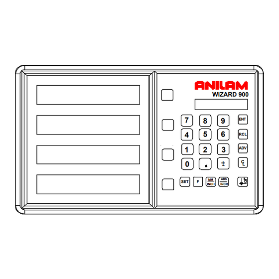
Page 8: The Anilam Wizard 450/450L Keypad And Display Windows
(Continued) The ANILAM Wizard 900/900E Keypad and Display Windows NOTE: The Wizard 900 DRO is available in 2-axis, 3-axis, and 4-axis models; the Wizard 900E DRO is available only in 3-axis models. For simplicity, most of the procedures in this manual describe a 3-axis model. -
Page 9: The Anilam Wizard 450/450L Back Panel
Introducing the Wizard (Continued) The ANILAM Wizard 900/900E Back Panel I/O Outputs Encoder Connection Connections I/O Option) RS 232 Cover Slot Connection I/O Option) I/O Inputs Connection I/O Option) ON/OFF Edge Switch Sensor Connection Power Cord Connection Ground Connection * I/O Option is standard on 900E. - Page 10 Introducing the Wizard (Continued) Your Wizard’s display was designed to be easy to read: Axis Indicator Indicates X or Z ABS RST INCH Coarse Resolution Diameter Mode Absolute Mode Axis Reset Only Correction Factor Reference Indicator MM or INCH Mode Edge Sensor Approaching Zero Indicator...
-
Page 11: First-Time User Checklist
First-Time User Checklist Your new DRO has many preset values. Before you proceed, please review the following list to verify default settings. If you need to change any setting(s), refer to Parameter Settings – F Description of Setting Factory Setting Your Setting 900 DRO 900E DRO... - Page 12 First-Time User Checklist (Continued) For your safety, and to prevent damage to the machine, please verify the following: 9. DRO arm and DRO are securely Yes/No mounted to the machine 10. The DRO Input-voltage switch on Yes/No the power-entry module (back panel) is set to the correct input voltage.
-
Page 13: About This Manual
About This Manual This manual contains limited text and enlarged graphics for easy use. Actual keystrokes are represented by graphics. The format is as follows: Function Heading Function Description Example with Keystrokes Explanation of Procedures and Observations NOTE: Indicates you must use caution. -
Page 14: Function Code List
Function Code List You can access most DRO features using function codes. Function codes are codes entered by pressing the Function key (F) and then pressing the two-digit code for the feature. The following table lists the function codes available with your DRO. The page number indicates where the function is described in this manual. - Page 15 Function Code List (Continued) F 24 Axis Designation F 25 Zero Output Time Select (With I/O Option Only) F 26 Feedrate ON/OFF F 27 RS-232 Setup (With I/O Option Only) RS-232 ON/OFF (With I/O Option Only) F 28 F 29 Mill/Lathe Setup (900 Only) Clear Datum...
- Page 16 Function Code List (Continued) F 60 Send Program to External Device (With I/O Option Only) F 61 Recall Program from External Device (With I/O Option Only) F 62 Print Program to External Printer (With I/O Option Only) F 63 Select Axis for Recall F 80 100-Point Axis Error Compensation F 81...
-
Page 17: Beeper Off/On - F 21
Beeper OFF/ON – F 21 The beeper is a standard feature on all ANILAM DROs. Use the beeper to acknowledge a keystroke. For correct keystrokes, a short tone sounds. For incorrect keystrokes, a long tone sounds. F 21 allows you to enable/disable the beeper in the DRO (Default: ON). -
Page 18: Keyboard Entry Error
Keyboard Entry Error If you enter an incorrect value, press the axis key again to clear the axis display. If you enter too many numbers on an axis, the DRO display reverts to zero on that axis. When this happens, enter the correct number again. -
Page 19: Inch/Metric Conversion
Inch/Metric Conversion This feature allows you to convert inch values to metric values and vice-versa on all axes. Example: Change 1.000 in. to its metric (mm) equivalent. 1. Press the desired axis key to select the axis. 2. Press The DRO displays the following: i.0000 INCH INCH... -
Page 20: Decimal Degree To Degree-Minutes-Seconds Conversion
Decimal Degree to Degree-Minutes-Seconds Conversion You can use every axis to display angular position when you connect a rotary encoder to the DRO. The display range is ± 360 degrees. NOTE: The axis must be set to rotary using Parameter Settings – F To convert all angular axis displays from decimal-degree display to degree-minutes- seconds display: 1. -
Page 21: Plus/Minus (±) Key
Change the sign of a preset value. Change the direction of travel on a linear encoder while in parameter setting. Add and subtract values. Scroll through options lists while making selections. Scroll through the Advanced Functions (ADV) list. WIZARD 900 Plus/Minus Key INCH INCR... -
Page 22: Absolute/Incremental (Abs/Incr) Key
Absolute dimension from the starting point on the axis display. Example: If a series of six 2.00 in. (50.8 mm) incremental moves are made, change to ABS Mode to display the total distance moved, which is 12.000 in. (304.80 mm). WIZARD 900 INCH INCR Absolute/Incremental... -
Page 23: Presetting A Dimension
Presetting a Dimension Presetting allows you to enter a dimension into an axis display. After you have preset the dimension, you can move the machine until the axis indicates zero. You can also use the preset feature as a one-line recall mode if the display is set in Incremental Mode. -
Page 24: Recalling A Preset Dimension
Recalling a Preset Dimension This feature allows you to recall a preset dimension to the axis display. Use this feature when making multiple moves of the same dimension. NOTE: This feature works only in Incremental Mode. To recall a preset dimension: INCR 1. -
Page 25: Clearing A Preset Dimension
Clearing a Preset Dimension When you clear a dimension, you automatically zero the previously entered dimension in an axis. To clear preset dimensions, one axis at a time: 1. Press the desired axis key to select the axis. 2. Press To clear entered dimensions for all axes: 1. -
Page 26: Resetting An Axis To Zero
Resetting an Axis to Zero When you reset an axis, the display for that axis reverts to zero Use the reset feature when establishing part zero (datum) or clearing the axis at each part location (making incremental moves). To reset one axis (X, Y, or Z): 1. -
Page 27: Axis Reset Only - F 16
Axis Reset Only – F 16 F 16 is useful for quick positioning. Press the axis key once to zero the display in either ABS or INCR Mode. Example 1: Set one axis as Axis Reset Only – for example, X-axis: 1. - Page 28 Axis Reset Only – F 16 (Continued) Example 2: Set two or more axes as Axis Reset Only – for example, X-axis and Y-axis: 1. Press to select the feature. The DRO displays the following in the message window: Axis reset 2.
-
Page 29: Absolute Zero Set - F 01
Absolute Zero Set – F 01 F 01 allows you to establish a part zero. The DRO clears all axis counters, both absolute and incremental, to zero. NOTE: This feature does not clear a preset dimension entered in Incremental Mode. To clear a dimension entered in Incremental Mode;... -
Page 30: Absolute Zero Set At Reference Mark - F 90
Absolute Zero Set at Reference Mark – F 90 F 90 allows you to reset one or more axes to zero at the reference mark. You must use this feature when you use 100-point axis error compensation (F 80/F 81). To reset all axes at the reference mark: 1. -
Page 31: Evertrack Tm Mode - F 02
EverTrack Mode – F 02 F 02 allows you to permanently store a part zero position (machine home, tool-change position, or datum). This allows you to return to a specific location on a workpiece such as when power fails before the work is complete. NOTE: This feature works ONLY with RBS-T and RBM-T linear encoders, which contain absolute reference marks. - Page 32 EverTrack Mode – F 02 (Continued) 5. Move the machine axis to the part zero position. 6. Press This will be the absolute part zero position. CAUTION: If you require a temporary datum while in EverTrack Mode, we recommend you exit the feature before you set the temporary datum. To exit EverTrack Mode: 7.
- Page 33 EverTrack Mode – F 02 (Continued) CAUTION: During the following step, do not change the machine axis travel direction. This will cause an error. 3. Move each machine axis approximately 1 in. (25.4 mm) in one direction until the RIs stop blinking and the display starts to count.
- Page 34 EverTrack Mode – F 02 (Continued) Recalling a Part Zero Position To recall a part zero position activate the RI as follows: One Axis 1. Press to select the feature. 2. Press the desired axis key. 3. Press The axis display resets to zero and the RI begins to blink. All Axes 1.
- Page 35 EverTrack Mode – F 02 (Continued) To exit EverTrack Mode: 5. Press 6. Press...
-
Page 36: Last Position Save/Recall - F 10/F 11
Last Position Save/Recall – F 10/F 11 F 10 allows you to save the machine’s last position before turning OFF the machine; F 11 allows you to recall the saved position after turning ON the machine. NOTE: If you have EverTrack Mode, you can always recall all datum points, even if you move the table during power-off. -
Page 37: Adding/Subtracting Values
Adding/Subtracting Values This feature allows you to add or subtract values using the axis display values. You can add/subtract a value to/from a value displayed for a machine position or for values you enter in an axis display. Example 1: The axis display indicates 3.425 in. (87 mm). To add 1.259 in. (32 mm) to this value: 1. -
Page 38: Dividing An Axis Value By 2
Dividing an Axis Value by 2 This feature allows you to divide a value on an axis display by 2. You can also divide any values entered in an axis display by 2. Example 1: The axis display indicates 7.126 in. (181 mm). To divide this value by 2: 1. -
Page 39: Centering Key
Centering Key The Centering Key allows you to center the tool on the centerline of the workpiece, or on a specific position on the workpiece. Example: To c enter the tool on the centerline of the workpiece: Position 3 Position 3 Position 1 Position 2 Position 1... - Page 40 Centering Key (Continued) The DRO displays the following in the message window: Edge 6. Move the tool to position 3. 7. Press The DRO displays the following in the message window: Edge 8. Move the tool to position 4. 9. Press 10.
-
Page 41: Radius/Diameter Per Axis - F 05
Radius/Diameter per Axis – F 05 F 05 allows you to display a specified axis in Radius or Diameter Mode. The DRO doubles axis movement and resolution In Diameter Mode. (Default for Lathe Mode: ON) Example 1: Set one axis display in Diameter Mode. 1. - Page 42 Radius/Diameter per Axis – F 05 (Continued) 2. Press the desired axis key(s) to select the axes. The DRO displays the radius-diameter mode indicator in the selected axis displays. X f 05 Radius-Diameter Mode Indicator Radius-Diameter Mode Indicator 3. Press to activate the feature.
-
Page 43: Setting A Correction Factor - F 03
Setting a Correction Factor – F 03 F 03 allows you to compensate for nominal linear inaccuracies due to your machine or for adding material shrinkage/expansion, as in mold work. The maximum allowable settings are ± 40%. Example: Consider a 1.325-in. (33.655 mm) travel on the display that is only 1.320 in. (33.528 mm) actual distance moved on the axis. - Page 44 Setting a Correction Factor – F 03 (Continued) The Correction Factor (CF) indicator in the displayed axis turns ON indicating the Correction Factor is active. i.320...
-
Page 45: 100-Point Axis Error Compensation - F 80/F 81
100-Point Axis Error Compensation – F 80/F 81 F 80/F 81 allow you to correct non-linear errors. The DRO allows setting a compensation table with a maximum of 100 different points per axis. This feature allows you to compensate for machine tool inaccuracies. To determine the compensation values it is necessary to measure the axis with a Laser Interferometer or other measuring device. - Page 46 100-Point Axis Error Compensation F 80/F 81 (Continued) Measure the Axis (Continued) 2. Press the desired axis key. INCR 3. Press key. The DRO displays the following in the message window: REF.DISPLAY The decimal point in the left display field indicates that the display values are referenced to the Reference mark.
-
Page 47: Selecting The Compensation Table, Entering An Axis Compensation
100-Point Axis Error Compensation F 80/F 81 (Continued) Selecting the Compensation Table, Entering an Axis Compensation 1. Press The DRO displays the following in the message window: SEL AXIS 5. Press the desired axis key. The DRO displays the following in the message window: AXIS X 6. - Page 48 100-Point Axis Error Compensation F 80/F 81 (Continued) Selecting the Compensation Table, Entering an Axis Compensation (Continued) Enter, for example: 0 mm Press The DRO displays the following in the message window: SPacing X Enter the spacing between the compensation points. Factory setting: 10 mm Enter, for example: 5 mm Press...
- Page 49 100-Point Axis Error Compensation F 80/F 81 (Continued) Selecting the Compensation Table, Entering an Axis Compensation (Continued) Press The DRO displays the following in the message window: NO. o1 5.000 X-axis display shows compensation point no. 1 - - - - - - - - - Y-axis display shows compensation value no.
-
Page 50: Key Functions For Compensation Table
100-Point Axis Error Compensation F 80/F 81 (Continued) Selecting the Compensation Table, Entering an Axis Compensation (Continued) NOTE: For 1-axis version, the compensation point displays only briefly in axis display, before compensation value is shown. If you press, the CE key, the compensation point is shown again. -
Page 51: Deleting A Compensation Value Table
100-Point Axis Error Compensation F 80/F 81 (Continued) Deleting a Compensation Value Table To delete a compensation value table: 1. Press The DRO displays the following in the message window: SEL AXIS 2. Select the table for the specified axis with the axis key. The DRO displays the following in the message window: AXIS X 3. -
Page 52: Axis Error Compensation On/Off
100-Point Axis Error Compensation F 80/F 81 (Continued) Axis Error Compensation ON/OFF 1. Press The DRO displays the following in the message window: 99 - pt.activ A programmed error compensation can be switched ON or OFF for each axis with the axis key. -
Page 53: Correction Factor Off/On - F 04
Correction Factor OFF/ON – F 04 F 04 allows you to turn the Correction Factor (CF) OFF or ON selectively and store the values in memory. To turn the correction factor ON or OFF: 1. Press to select the feature. The DRO displays the following in the message window: Cf on--off 2. -
Page 54: Approaching Zero Indicator
Approaching Zero Indicator This feature indicates that the machine is within a set range and is approaching zero. The approaching zero indication range must be set using Approaching Zero Range – Apz set .0000 Approaching Zero Indicator... -
Page 55: Approaching Zero - F 06
Approaching Zero – F 06 F 06 indicates when an axis is within a set range and approaching zero, or at zero. 1. Press to select the feature. The DRO displays the following in the message window and axis displays: Apz set X f 06 2. - Page 56 Approaching Zero – F 06 (Continued) To turn the approaching zero indicator OFF: 1. Press to select the feature. 2. Press the desired axis key to deselect the axis. 3. Press NOTE: The following example shows an axis with an approaching zero position tolerance set to .5.
-
Page 57: Approaching Zero Range - F 07
Approaching Zero Range – F 07 F 07 allows you to set the range for approaching zero indication in one or more axes. Example: To set the range for the X-axis to .5: 1. Press to select the feature. The DRO displays the following in the message window: Apz range The axis displays indicate the current approaching zero range. - Page 58 Approaching Zero Range – F 07 (Continued) To set the range for another axis: 4. Repeat steps 2 and 3 for each axis. 5. Press to activate the feature.
-
Page 59: Approaching Zero Audio On/Off - F 08
Approaching Zero Audio ON/OFF – F 08 F 08 enables/disables an audible beep to notify you when the selected axis is within the approaching zero range. (Default: OFF) To turn on audio notification for the selected axis: 1. Press The DRO displays the following in the message window: Apz audio To turn off audio notification for the selected axis: 1. -
Page 60: Connecting The Edge Sensor Probe
Connecting the Edge Sensor Probe CAUTION: To avoid electrical shock, unplug the DRO from the power source. 1. Connect the ground wire on the back of the DRO to a proper earth ground. 2. Place the round spring clip in the appropriate groove on the probe. NOTE: Ensure that the round spring clip on the probe cable is connected to the probe below the LED. -
Page 61: Edge Sensor Probe - F 09
Edge Sensor Probe – F 09 F 09 allows you to position the spindle on the edge of the workpiece. To activate the edge sensor probe: 1. Press The DRO displays the following in the message window: Probe edge NOTE: When you move the X-axis from left to right enter a positive diameter; when you move the X-axis from right to left enter a negative diameter (See Figure 1). - Page 62 Edge Sensor Probe – F 09 (Continued) To enter the probe diameter: 3. Press to toggle to plus or minus, for the desired direction of movement (See Figure 1). 4. Press The DRO displays the following in the message window and axis display: Probe x + .0000 Edge Sensor Indicator...
-
Page 63: Feedrate On/Off - F 26
Feedrate ON/OFF – F 26 F 26 allows you to display the maximum feedrate for all axes in the message window (if feedrate is greater than 0.4 inches per minute or greater than 10 mm per minute). The DRO displays the feedrate in inches per minute if set to INCH Mode and mm per minute if set to MM Mode. -
Page 64: Job Clock On/Off - F 34
Job Clock ON/OFF – F 34 F 34 allows you to toggle the DROs integrated job clock ON or OFF. When activated, the job clock displays the time in hours, minutes, and seconds in the message window. (Default: OFF) To turn the job clock ON: 1. - Page 65 Job Clock ON/OFF – F 34 (Continued) To turn the job clock OFF: 1. Press The DRO temporarily displays the following in the message window: Clock off The DRO clears the job clock display in the message window and resets the axis display windows to 0 (zero).
-
Page 66: Parameter Settings - F 20
Parameter Settings – F 20 F 20 allows you to set up encoder parameters and axis display resolutions. The following section describes two different types of resolution: Encoder Resolution the resolution of the measurement, an encoder parameter. Display Resolution the resolution of displayed values. You can vary the resolution of the values displayed in the linear axis displays for both INCH and MM Mode. - Page 67 NOTE: Most linear encoders, and all modern ANILAM encoders are metric, i.e., they have a grating pitch measured in microns (µm). Some older linear encoders (for example, BT and JB type encoders) are inch-based, i.e., they have a grating pitch measured in inches.
-
Page 68: Metric Linear Encoders
The axis designation (in this example, X) is blinking, indicating that you can enter a value. The default value for the encoder resolution is 5µm. The encoder resolution value must be set for the linear encoder type you are using. The following table lists the encoder resolution (in microns) for common ANILAM encoders: Encoder... - Page 69 MM Mode only. The axis designation (in this example, X) is blinking, indicating that you can enter a value. The DRO will default the same display resolution as the encoder resolution. ANILAM recommends that you use the same display resolution as you use for the encoder resolution.
- Page 70 MM/INCH key has been toggled to INCH Mode only. The axis designation (in this example, X) is blinking, indicating that you can enter a value. The DRO will default the same display resolution as the encoder resolution. ANILAM recommends that you use the same display resolution as you use for the encoder resolution.
- Page 71 Parameter Settings – F 20 (Continued) To change the Resolution Setting: 2. Press to select the desired display resolution in INCH Mode. Setting EverTrack Mode The DRO prompts for the EverTrack Mode in the message window and displays the default EverTrack Mode in the axis display: E--trac set INCH...
-
Page 72: Inch Linear Encoders (Bt Or Jb Linear Encoders)
NOTE: If you do not know the encoder resolution for the linear encoder(s) you are using, call ANILAM at the number listed on page 1. Setting Encoder Resolution If you need to change the encoder resolution setting – for example, .0002 in.: 1. -
Page 73: Rotary Encoders
Parameter Settings – F 20 (Continued) Rotary Encoders If you have performed steps 1 through 4 in the Setting Up Encoder Parameters section and selected rot (Rotary Encoder), the DRO prompts for the Line Count in the message window. The default rotary encoder line count (9000) is displayed in the axis display: Line count 9000 The axis designation (in this example, X) is blinking, indicating that you can enter a value. - Page 74 The DRO will default the same display resolution as the encoder resolution (in this example, .0I Degrees). ANILAM recommends that you use the same display resolution as you use for the encoder resolution.
- Page 75 The DRO will default the same display resolution as the encoder resolution (in this example, 30 seconds). ANILAM recommends that you use the same display resolution as you use for the encoder resolution.
- Page 76 Parameter Settings – F 20 (Continued) Resetting Parameters to Factory Settings To reset all parameter settings to their original factory settings: 1. Press for approximately 5 seconds. To cancel the reset: 2. Press again. To reset all parameters: 1. Press...
-
Page 77: Display Dim Off/On - F 22/ F 23
Display Dim OFF/ON – F 22/F 23 F 22 allows you to activate Dim Mode; F 23 allows you to deactivate Dim Mode. To increase the life of the display, the DRO automatically dims if it is not used for 15 minutes (similar to a computer terminal’s screen-saver mode). -
Page 78: Axis Designation - F 24
Axis Designation – F 24 F 24 allows you to assign an axis to each display you select. You can change the assignment of any axis to X, Y, Z, W, Z or no axis designation. 1. Press to select the feature. The DRO displays the following in the message window and axis display: Name axis X f 24... -
Page 79: Select Language - F 99
Select Language – F 99 F 99 allows you to select the language the DRO will use to display text and messages. The available languages are: English German French Italian Spanish Swedish Czech Portuguese To select the language: 1. Press The DRO displays the selected language in the message window: english... -
Page 80: Linear Encoder Error Detect Off/On - F 40/F 41
Linear Encoder Error Detect OFF/ON – F 40/F 41 Your DRO has advanced Linear Encoder error-checking capability. This feature determines if there are any Linear Encoder miscounts or repeatability problems. F 40 allows you to turn OFF Linear Encoder Error Detect; F 41 allows you to turn ON Linear Encoder Error Detect. -
Page 81: Diagnostics - F 45
F 45 allows you to perform system diagnostic tests on the keyboard, internal EEPROM, and internal counters. If any of these tests fail, contact your local distributor or ANILAM Customer Services. You do not need to unplug the linear encoders for these tests. - Page 82 Diagnostics – F 45 (Continued) Keyboard Test 4. Press to activate the keyboard test. 5. Press any key on the DRO to display the key on the DRO display. Blank Test 6. Press for 2 seconds to blank all segments of the display.
- Page 83 Mill/Lathe Setup (900 Only) – F 29 F 29 allows you to set up the DRO to operate in Mill or Lathe Mode. (Default is Mill) To set up the DRO in Mill or Lathe Mode: 1. Press The DRO displays one of the following in the message window: mill lathe 2.
-
Page 84: Advanced (Adv) Functions Key
Advanced (ADV) Functions Key The Advanced Functions Key allows you to access the following DRO advanced functions: Help for DRO Features Bolt-Hole Patterns (N/A for 900, Lathe Mode) Linear-Hole/Frame Hole Patterns (N/A for 900, Lathe Mode) Taper Calculation (900, Lathe Mode Only) Skew Compensation (900, Mill Mode Only) NOTE: To select Mill or Lathe Mode for a 900, use... - Page 85 Advanced (ADV) Functions Key (Continued) The DRO displays the following in the message window: PRESS + -- 2. Press repeatedly to scroll through the feature list. The DRO displays the following in the message window and axis display 1: ABS SET Each time you press the plus/minus key, the DRO displays the next feature code in axis display 1 and the feature name in the message window.
-
Page 86: Bolt-Hole Pattern Function (450 Only)
Advanced (ADV) Functions Key (Continued) Bolt-Hole Pattern Function (N/A for 900, Lathe Mode) The Bolt-Hole Pattern function allows you to program the X and Y positions for a maximum of 10 different bolt-hole patterns (maximum 360 holes each) around the circumference of a specified circle. - Page 87 Advanced (ADV) Functions Key (Continued) Diameter: 2.00 inches (50.8 mm) Beginning Angle: -10 Hole 2 Holes: X Center: +1.00 inch (25.4 mm) Y Center: +1.00 inch (25.4 mm) Hole 3 Hole 1 1.00 Inch Hole 4 1.00 Inch Figure 3: Full Bolt-Hole Pattern To access the Bolt-Hole pattern function: 1.
-
Page 88: Partial Bolt-Hole Pattern
Advanced (ADV) Functions Key (Continued) NOTE: If you are entering a full bolt-hole pattern, skip this section and go to the Full Bolt-Hole Pattern section. Partial Bolt-Hole Pattern To enter a partial bolt-hole pattern for program number 1 (Range is 0 through 9): 1. - Page 89 Advanced (ADV) Functions Key (Continued) To enter the X dimension for the center of the pattern – for example, 1.00 in. (25.4 mm): 4. Press The DRO displays the following in the message window and axis display 2: CENTER .0000 To enter the Y dimension for the center of the pattern –...
- Page 90 Advanced (ADV) Functions Key (Continued) The DRO displays the following in the message window and axis display 1: HOLE To enter the number of bolt-hole patterns (maximum 360 holes) – for example, 3: 7. Press The DRO displays the following in the message window and axis display 1: BEG ANGLE .0000 To enter the beginning angle for the first hole (measured in a counter clockwise direction)
- Page 91 Advanced (ADV) Functions Key (Continued) To enter the end angle for the pattern (measured in a counter clockwise direction) – for example, for 80 degrees: 9. Press The DRO temporarily displays the following in the message window: Bhp done...
-
Page 92: Full Bolt-Hole Pattern (450 Only)
Advanced (ADV) Functions Key (Continued) Full Bolt-Hole Pattern (N/A for 900, Lathe Mode) To access the Full Bolt-Hole Pattern function: 1. Press repeatedly to scroll through the Advanced Functions list. When the DRO displays the following in the message window: BOLT HOLE 2. - Page 93 Advanced (ADV) Functions Key (Continued) The DRO displays the following in the message window: full 5. Press The DRO displays the following in the message window and axis display 1 X CENTER .0000 To enter the X dimension for the center of the pattern – for example, 1.00 in. (25.4 mm): 6.
- Page 94 Advanced (ADV) Functions Key (Continued) The DRO displays the following in the message window and axis display 1 BHP DIA .0000 To enter the diameter of the bolt-hole pattern – for example, 2.00 in. (50.8 mm): 8. Press The DRO displays the following in the message window and axis display 1 HOLE To enter the number of bolt-hole patterns (maximum 360 holes) –...
- Page 95 Advanced (ADV) Functions Key (Continued) To enter the beginning angle for the first hole (measured in a counter clockwise direction) – for example, -10 degrees: 10. Press The DRO temporarily displays the following in the message window: Bhp done...
-
Page 96: Recalling Bolt-Hole Pattern Function (450 Only)
Advanced (ADV) Functions Key (Continued) Recalling Bolt-Hole Pattern Function (N/A for 900, Lathe Mode) The Recall Key (RCL) allows you to recall a maximum of 10 previously programmed bolt–hole patterns. To recall bolt-hole pattern number 1 programmed in the previous section: 1. - Page 97 Advanced (ADV) Functions Key (Continued) The DRO displays the following in the message window and the axis displays: I HOLE 00i - i.4924 - .9i32 The message window indicates bolt-hole pattern number 1 and hole number 1. The axis displays show the distance to hole number 1. 4.
- Page 98 Advanced (ADV) Functions Key (Continued) The message window indicates bolt-hole pattern number 2 and hole number 2. The axis displays show the distance to hole number 2. 6. Move the machine until the axis displays indicate zero and drill the hole. To recall the distance to hole number 3: 7.
-
Page 99: Linear-Hole/Frame-Hole Pattern Function (450 Only)
Advanced (ADV) Functions Key (Continued) Linear-Hole/Frame-Hole Pattern Function (N/A for 900, Lathe Mode) The Linear Hole pattern function allows you to program a combination of 10 different linear-hole patterns or frame-hole patterns. Each pattern can include a maximum of 999 holes. - Page 100 Advanced (ADV) Functions Key (Continued) To program a linear-hole pattern (Range is 0 through 9) – for example, linear-hole pattern number 3: 3. Press The DRO displays the following in the message window: lin hole If you are programming a linear-hole pattern go to step 5. Figure 5: Frame-Hole Pattern To select Frame-Hole Pattern: 4.
- Page 101 Advanced (ADV) Functions Key (Continued) To enter a frame-hole pattern: 5. Press The DRO displays the following in the message window: X hole i To enter the dimension for hole 1 on the X-axis – for example, 1.00 in. (25.4 mm): 6.
- Page 102 Advanced (ADV) Functions Key (Continued) The DRO displays the following in the message window: Qt hole x To enter the number of holes on the X-axis – for example, 4: 8. Press The DRO displays the following in the message window: X -- X cent To enter the incremental distance between holes on the X-axis –...
- Page 103 Advanced (ADV) Functions Key (Continued) The DRO displays the following in the message window: -- cent To enter the incremental distance between holes on the Y-axis – for example, 1.00 in. (25.4 mm): 11. Press The DRO displays the following in the message window: X004 The message window indicates the calculated holes in the X-axis (4 holes) and the Y-axis (4 holes).
-
Page 104: Recalling Linear-Hole/Frame-Hole Function (450 Only)
Advanced (ADV) Functions Key (Continued) Recalling Linear-Hole/Frame-Hole Function (N/A for 900, Lathe Mode) The Recall Key (RCL) allows you to recall a maximum of 10 previously programmed linear bolt–hole patterns. To recall linear-hole pattern number 3 programmed in the previous section: 1. - Page 105 Advanced (ADV) Functions Key (Continued) The DRO displays the following in the axis displays and the message window: I HOLE 00i - i.9848 - .8264 The message window indicates bolt-hole pattern number 1 and hole number 1. The axis displays show the distance to hole number 1. 4.
- Page 106 Advanced (ADV) Functions Key (Continued) The message window indicates bolt-hole pattern number 2 and hole number 2. The axis displays show the distance to hole number 2. 6. Move the machine until the axis displays indicate zero and drill the hole. 7.
-
Page 107: Taper Calculator Function (450L Only)
Advanced (ADV) Functions Key (Continued) Taper Calculator Function (900, Lathe Mode Only) The Taper Calculator function allows you to preset a taper angle on the lathe cross slide attachment without having to make a test cut. This function can also be used to calculate the taper on a workpiece. - Page 108 Advanced (ADV) Functions Key (Continued) 4. Press The DRO displays the following in the message window: XZ Pos 2 5. Move to position 2. 6. Press The DRO displays the taper angle in the message window: + 28.i38 deg Position Position Calculated angle: 28.138 degrees To exit the Taper Calculator function:...
- Page 109 Advanced (ADV) Functions Key (Continued) Skew Compensation (900, Mill Mode Only) Skew compensation allows you to drill holes on a workpiece without aligning the workpiece on the machine. This feature can electronically align the workpiece on the machine for setup. Use this feature only for drilling holes. To access the Skew Compensation function: 1.
- Page 110 Advanced (ADV) Functions Key (Continued) To enter the diameter of the tool or edge sensor probe – for example, .25 in. (6.35 mm): 3. Press The DRO turns off the axis displays and displays the following in the message window: Home pos 4.
- Page 111 Advanced (ADV) Functions Key (Continued) The DRO displays the following in the message window: I pos 10. Move to position 3 and touch the workpiece with the tool or edge sensor probe. 11. Press The DRO displays the following in the message window: 2 pos 12.
- Page 112 Advanced (ADV) Functions Key (Continued) The DRO automatically compensates for the misaligned workpiece on the machine. To exit the Skew Compensation feature: 17. Press NOTE: When you recall a program with activated skew compensation, the DRO displays a blinking S on the left side of the message window.
- Page 113 The Datum/Tool Offset Key is a dual-function key. When you set the DRO in 900, Mill Mode or 900E, the key functions as the Datum Key. When you set the DRO in 900, Lathe Mode, the key functions as the Tool Offset Key. WIZARD 900 Datum/Tool Offset Key...
-
Page 114: Enter Datum
Datum Key (N/A for 900, Lathe Mode) The Datum Key allows you to enter a datum table (maximum 99 datum points). A datum is a point or reference location, from which you can machine a part. Datum points allow you to machine similar programs on different parts. After you machine a group of parts, you can place a new group on the machine and machine the same programs on the new parts. - Page 115 Datum (N/A for 900, Lathe Mode) (Continued) 5. Press The DRO displays the following in the message window: Datum 00 6. Press The DRO displays the following in the message window: Datum 0i 7. Establish a part zero using Absolute Zero Set – F Datum 1 is set.
- Page 116 Datum Key (N/A for 900, Lathe Mode) (Continued) The DRO displays the following in the message window: Datum 02 11. Establish a part zero using Absolute Zero Set – F Datum 2 is set. 12. Move the tool to the corner of part 3 (indicated by the black dot). 13.
-
Page 117: Enter Datum (Alternate Method)
Datum Key (N/A for 900, Lathe Mode) (Continued) Enter Datum (Alternate Method) If you know the axis locations for the corner of the parts, you can enter the datum table for the previous example without moving the tool from the machine home position as follows: 1. - Page 118 Datum Key (N/A for 900, Lathe Mode) (Continued) 9. Press the axis key for the X-axis. 10. Press to enter the X-axis value, 2 in. (50.8 mm). 11. Press the axis key for the Y-axis. 12. Press to enter the Y-axis value, 1 in.
-
Page 119: Recall Datum
Datum Key (N/A for 900,Lathe Mode) (Continued) Recall Datum Recall Datum allows you to recall a preset datum. Example: To recall datum 1 from the previous example: 1. Press While the datum is activated, the DRO displays the following in the message window: Datum 0i 2. -
Page 120: Clear Datum - F 31
Datum Key (N/A for 900, Lathe Mode) (Continued) Clear Datum – F 31 Clear Datum (F 31) allows you to clear all preset datum points (maximum 99) before entering new information. To clear all datum points: 1. Press The DRO temporarily displays the following in the message window: Del datum When the DRO resets the message window and axis displays, it clears all preset datum values from memory. -
Page 121: Enter Tool Offset
Tool Offset Key (900, Lathe Mode Only) The Tool Offset Key allows you to preset X and Z offsets for each tool into a tool table (maximum 99). This feature requires an interchangeable tool system. NOTE: Before entering a tool offset, establish a machine home position using Absolute Zero Set –... - Page 122 Tool Offset Key (900, Lathe Mode Only) (Continued) 1.00 Inch Z Axis Zero (25.4 mm) Reference Point 2.376 Inches (56.35 mm) Tool Number 1 Inside Workpiece Tool Number 1 at Corner of Workpiece 3. Move the tool to the workpiece and make a skim cut on the diameter, about 1 in. (25.4 mm), to allow a micrometer to measure the workpiece.
-
Page 123: Recall Tool Offset
Tool Offset Key (900, Lathe Mode Only) (Continued) 11. Repeat these procedures by touching each tool on the same reference point on the workpiece. If you do not require tool offset for a tool: 12. Press The DRO displays the following in the message window: Tool 00 Recall Tool Offset Recall Tool Offset allows you to recall a previously set tool offset (Range: 1 through 99). -
Page 124: Modify Tool Offset - F 35
Tool Offset Key (900, Lathe Mode Only) (Continued) Modify Tool Offset – F 35 Modify Tool Offset (F 35) allows you to modify the Z-axis tool-offset value for all tools without reentering values. If you place a new part with a different length in the chuck, you must modify all the Z-axis tool offsets in the tool table. -
Page 125: Clear Tool Offset - F 32
Tool Offset Key (900, Lathe Mode Only) (Continued) Clear Tool Offset – F 32 Clear Tool Offset (F 32) allows you to clear all preset tool offset values (99 tools) before entering new information. To clear all preset tool offset values: 1. - Page 126 Axis Coupling (900, 3-/4-Axis Only) – F 18/F 19 F 18 and/or F 19 allow you to sum 2 parallel axes on 1 axis display. This allows you to move the coupled axes independently while the DRO automatically calculates the true tool position.
- Page 127 Axis Coupling (900, 3-/4-Axis Only) – F 18/F 19 (Continued) The DRO temporarily displays the following in the message window: Coup on The DRO clears the COUP ON message and displays the following in the message window. X + Xi Z + zi indicating the summed axes.
- Page 128 Electronic Notepad The Electronic Notepad allows you to program information into the DRO memory. You can program a maximum of 500 lines. Each line contains the desired position, which datum point it refers to (Mill Mode) or which tool (Lathe Mode), and whether the move is in Absolute or Incremental Mode.
- Page 129 Electronic Notepad (Continued) Entering Axis Dimensions To enter axis dimensions into the Electronic Notepad: INCR 2. Press to select the Absolute or Incremental Mode. NOTE: In all cases, set the first line of a program to ABS (Absolute) Mode. If required, you can specify a new Datum (Mill Mode) or Tool (Lathe Mode) – for example, Datum 1: 3.
- Page 130 Electronic Notepad (Continued) The DRO displays the following in the message window: Ent 000 indicating memory location 000. The DRO, by default, indicates the first empty memory location as the first line of a new program. To store the entered axis dimensions into line 000: 11.
- Page 131 Electronic Notepad (Continued) To exit Axis Dimension Entry: 13. Press NOTE: When you exit, the DRO automatically stores a PRG END in the first memory location after the last line. This allows you to exit the axis dimension entry mode, before you finish the program and return later to complete the program by specifying one less than the memory location prompted by the DRO.
- Page 132 Electronic Notepad (Continued) Entering Axis Dimensions by Teach-In As an alternative to manually entering the axis dimensions, you can store the program the first time you machine the workpiece. 1. Make sure you properly zero the DRO or set the datum for the starting position. 2.
- Page 133 Electronic Notepad (Continued) Entering Bolt-Hole/Linear-Hole Patterns The DRO allows you to store a bolt-hole or linear-hole pattern on one line in the Electronic Notepad (only in Absolute Mode). NOTE: To use a bolt-hole or linear/frame-hole pattern in the Electronic Notepad, you must first program the hole pattern using the Advanced Functions, Bolt-Hole Pattern function.
- Page 134 Electronic Notepad (Continued) 4. Press to select the desired type of hole pattern. The DRO displays one of the following in the message window: Bhp number Lhp number To enter the desired pattern number – for example, BHP number 1: 5.
- Page 135 Electronic Notepad (Continued) Recalling Dimensions The DRO allows you to recall programmed information from the Electronic Notepad. You must know the memory location for the first line in the program you want to recall. NOTE: Before you recall information from the Electronic Notepad, establish a machine home position using Absolute Zero Set –...
- Page 136 Electronic Notepad (Continued) The values displayed on the axis displays indicate the distance to the programmed position. 3. Move the machine axis until the displays indicate zero. This is the first position stored in the Electronic Notepad. 4. Press to recall the next line in the Electronic Notepad.
- Page 137 Electronic Notepad (Continued) To exit the recall feature: 8. Press...
- Page 138 Electronic Notepad (Continued) Clearing the Electronic Notepad You can clear all 500 lines (including bolt-hole and linear-hole patterns) from the Electronic Notepad before you enter new information. To clear information from the Electronic Notepad: 1. Press The DRO momentarily displays the following in the message window: Mem clear The DRO clears the message window, axis displays, and all 500 Electronic Notepad lines.
- Page 139 Electronic Notepad (Continued) To insert/delete a line to/from the Electronic Notepad – for example, line 003: 3. Press 4. Press If you selected Delete, the DRO deletes the line from the Electronic Notepad. If you selected insert, you can program a line on the new line number in the Electronic Notepad.
- Page 140 Select Axis for Recall – F 63 F 63 allows you to specify which axis dimensions the DRO recalls from the Electronic Notepad when you press the RCL key. You can recall dimensions for all axes or for one or more specific axes. To select axis dimensions for recall: 1.
- Page 141 Mirror Image – F 17 After you enter dimensions in the Electronic Notepad, F 17 allows you to reverse or mirror all positions on the X-axis and/or Y-axis without re-entering the positions. Example 1: To set the X-axis as a mirror image: 1.
- Page 142 Mirror Image – F 17 (Continued) 2. Press axis key 1. The DRO displays the following in the message window: Mirror x 3. Press axis key 2. The DRO displays the following in the message window: Mirror x 4. Press NOTE: When you recall a program with mirror image activated, the DRO displays a blinking M on the left side of the message window.
-
Page 143: Output Connections (With I/O Option Only)
Output Connections (With I/O Option Only) Output connections are located on the back of the DRO. When DRO functions are activated, the DRO generates signals through these connections to operate external devices. Each output can sink 500 mA of current when active. The output load of Relay 1 and Relay 2 should be a maximum of 10 VA (maximum 20 Volts, 0.75 A). -
Page 144: Input Connections (With I/O Option Only)
Input Connections (With I/O Option Only) Input connections are located on the back of the DRO. These connections allow signals from external devices to activate specific DRO functions. DRO functions are activated by applying a +24 VDC, 10 mA signal for a minimum of 100 ms. -
Page 145: Zero Output On/Off (With I/O Option Only) - F 33
Zero Output ON/OFF (With I/O Option Only) – F 33 F 33 allows you to toggle the zero output ON or OFF. (Default: OFF) To turn the zero output ON: 1. Press The DRO displays the zero output setting in each axis display and the following in the message window: Zero out 2. - Page 146 Approaching Zero Output Axis Select (900 With I/O Option Only) – F 14 F 14 allows you to specify which axis the DRO will use for approaching zero ( ) output. When the selected axis is within the range preset using Approaching Zero Range –...
-
Page 147: Zero Output Time Select (With I/O Option Only) - F 25
Zero Output Time Select (With I/O Option Only) – F 25 F 25 allows you to specify the time for which a remote device is turned on when the selected axis crosses zero. (Default: 100 ms) Zero Output – F 33 must be ON. -
Page 148: Interface (With I/O Option Only)
RS-232 Interface (With I/O Option Only) The RS-232 Interface connection is located on the back of the DRO. This connection allows you to exchange data with other RS-232 devices. DE 9 Connector (Female) Pin 1 Not Used Pin 2 TxD (Transmit Data) Pin 3 RxD (Receive Data) Pin 4... -
Page 149: Setup (With I/O Option Only) - F 27
RS-232 Setup (With I/O Option Only) – F 27 F 27 allows you to set up the following parameters for the RS-232 port: Baud Rate Parity Data Bits Printer or Computer Output To set up RS-232 port parameters: 1. Press The DRO displays the following in the message window: 300 baud The available baud rates are:... - Page 150 RS-232 Setup (With I/O Option Only) – F 27 (Continued) The available selections are: NO PARITY (default) EVEN PARITY ODD PARITY 4. Press repeatedly to scroll through the options. 5. Press to set the parity. The DRO displays the following in the message window: 8 data--bit The available selections are: 8 Data Bit (default)
- Page 151 RS-232 Setup (With I/O Option Only) – F 27 (Continued) The DRO displays one of the following in the message window: printer computer The available selections are:: PRINTER (default) Each output of a string ends with a Carriage Return (CR) and a Line Feed (LF).
-
Page 152: On/Off (With I/O Option Only) - F 28
RS-232 ON/OFF (With I/O Option Only) – F 28 F 28 allows you to toggle the RS-232 port ON or OFF. (Default: OFF) To toggle the RS-232 port ON: 1. Press The DRO displays the following in the message window: Rs 232 on To toggle the RS-232 port OFF: 1. -
Page 153: Printing Axis Values (With I/O Option Only)
Printing Axis Values (With I/O Option Only) NOTE: Before sending data to the printer, ensure that the DRO is not in the Preset Mode. To print axis values to a printer: 1. Press to print the data from axis 1. 2. -
Page 154: Remote Operation (With I/O Option Only)
Remote Operation (With I/O Option Only) You can remotely operate the DRO from an IBM-compatible computer running a terminal program via the RS-232 Interface connection. The baud rate, parity, and data bit settings of the DRO and the terminal (or computer) must agree, and RS-232 must be ON. After you activate the RS-232 link, you can operate the DRO by pressing the computer keyboard. - Page 155 Send Program to External Device (With I/O Option Only) – F 60 F 60 allows you to send a program to an external device (such as a PC or disk drive) using the RS-232 port. NOTE: The RS-232 port must be toggled ON using RS-232 ON/OFF –...
- Page 156 Recall Program from External Device (With I/O Option Only) – F 61 F 61 allows you to recall a program from an external device (such as a PC or disk drive) using the RS-232 port. NOTE: The RS-232 port must be toggled ON using RS-232 ON/OFF –...
- Page 157 Print Program to External Printer (With I/O Option Only) – F 62 F 62 allows you to print a program to an external printer or PC using the RS-232 port. NOTE: The RS-232 port must be toggled ON using RS-232 ON/OFF – F To print a program to an external device: 1.
- Page 158 Relay 1/Relay 2 Setup (900 With I/O Option Only) – F 38/F 39 F 38 and F 39 allow you to set up the parameters for Relay 1 and Relay 2. The following procedures for setting up parameters for Relay 1 also can be used to set up parameters for Relay 2.
- Page 159 Relay 1/Relay 2 Setup (900 With I/O Option Only) – F 38/F 39 (Continued) 6. Press to toggle between Direct Signal and Coincidence Pulse. 7. Press If you select Coincidence Pulse, you can change the output time. The available output times for Coincidence Pulse are: Coincidence Pulse Output Time 100 ms (default), 500 ms, 1 sec,...
- Page 160 Relay 1/Relay 2 Setup (900 With I/O Option Only) – F 38/F 39 (Continued) 10. Press the desired axis key. 11. Press to enter the value for the switch off point. NOTE: You can assign each relay to each axis. Direction Signal Coincidence Pulse Switch off Value...
- Page 161 APZ OUT RELAY 1 RELAY 2 If any of these tests fail, contact your local distributor or ANILAM Customer Services. To start the output tests: 1. Press The DRO turns on each available output for approximately 1 second. The message window displays the name of each output test and the beeper sounds a short beep when each test is complete.
- Page 162 Constant Surface Speed (CSS) Setup (900 With CSS and I/O Options) If your DRO has the CSS option, you can use the DAC (Digital/Analog Converter) output voltage to control the spindle speed. You can vary the DAC output voltage between 0V and 10V with 12-bit resolution.
- Page 163 DAC Output Voltage Setup (900 With CSS and I/O Options) – F 96 F 96 allows you to set up the DAC output voltage. To set up the CSS feature: 1. Press to select DAC voltage setup. The DRO displays the following in the message window: Rpm 0v gi prompting for the spindle speed at 0V for Gear 1.
- Page 164 DAC Output Voltage Offset Adjustment (900 With CSS and I/O Options) – F 97 F 97 allows you to adjust the DAC output voltage offset. You will require a digital multimeter to perform this feature. To set up the CSS feature: 1.
- Page 165 DAC Output Voltage Test (900 With CSS and I/O Options) – F 98 F 98 allows you to verify the DAC output voltage setting. To verify DAC output voltage setting: 1. Connect a multimeter between Pin 15 and Pin 8 and measure the DAC output voltage.
- Page 166 Constant Surface Speed (CSS)/Direct RPM Operation (900 With CSS and I/O Options) If your DRO has the CSS option, you can use the DAC (Digital/Analog Converter) output voltage to control the spindle speed. You can use this feature in Lathe Mode to obtain a constant surface speed as the tool changes the workpiece diameter.
- Page 167 CSS/Direct RPM Input (900 With CSS and I/O Options) – F 48 F 48 allows you to specify the desired Constant Surface Speed (CSS), which is entered in Feet per Minute (INCH Mode) or Meters per Minute (MM Mode). The DRO maintains the specified constant surface speed as the diameter of the workpiece changes.
- Page 168 CSS/Direct RPM Input (900 With CSS and I/O Options) – F 48 (Continued) The DRO displays one of the following in the message window (depending on the number of available gears): Gear i Gear 2 4. Press to toggle and select the desired gear.
- Page 169 CSS/Direct RPM Input (900 With CSS and I/O Options) – F 48 (Continued) The X-axis display indicates the previously used surface speed. The X designation is blinking, indicating you can enter a value. If the displayed surface speed is acceptable: 6.
- Page 170 DAC Output Voltage ON/OFF (900 With CSS and I/O Options) – F 50 F 50 allows you to turn the DAC output voltage ON or OFF: To turn the DAC output voltage ON or OFF: 1. Press The DRO displays one of the following in the message window: DAC off DAC OUt on 2.
- Page 171 Parameter Setting for Spindle Speed Display (2-Axis and 3-Axis, With SSD Option Only) If your DRO has the SSD Option, it includes a separate display in addition to the regular axis displays. For example, a 2-axis DRO with the SSD Option has 3 axis displays. The extra display (at the bottom of the DRO) indicates the spindle speed in revolutions per minute (RPM).
- Page 172 Parameter Setting for SSD (2-Axis and 3-Axis, With SSD Option Only) (Continued) The DRO displays the following in the message window and in the SSD display: Line count i000 indicating the default line count. To enter the line count for the rotary encoder – for example, 1500 lines: 4.
- Page 173 EDM Features (900E Only) The Wizard 900E is a high-performance programmable DRO designed for EDM applications. The 900E includes the I/O Option as standard. NOTE: The Z-axis (Axis 3) must be used as the spark erosion axis for the EDM functions to work correctly.
- Page 174 EDM Features (900E Only) (Continued) For Example: The DRO is in EDM Mode and the axis displays indicate the following: i.4i5 Remaining distance to Target Depth 5.200 Desired Z-Depth 3.785 Actual position relative to the zero position...
- Page 175 EDM Features (900E Only) (Continued) First Spark Detection Setup allows you to define how you activate the EDM Mode. It can be either manually activated or automatically activated if the DRO receives a signal from a first spark detector. The position at which the first spark occurs is the Zero position.
- Page 176 EDM Features (900E Only) (Continued) ELECTRODE ELECTROLYTE SparkArrest Limit Zero Position Target Z-Depth WORKPIECE Z-Depth to Go Figure 6: EDM Setup...
- Page 177 First Spark Detection Setup (900E Only) – F 46 F 46 allows you to define how you activate the EDM Mode. It can be either manually activated or automatically activated if the DRO receives a signal from a first spark detector.
- Page 178 First Spark Detection Setup (900E Only) – F 46 (Continued) SPARK OFF – No First Spark Detection NOTE: Lower the electrode until it touches the workpiece or the first spark occurs. This is the zero position. 5. Press the Z-axis key to zero the axis display.
- Page 179 First Spark Detection Setup (900E Only) – F 46 (Continued) SPARK MAN – Manual First Spark Detection NOTE: You must also set up the desired EDM features using the procedures described Relay 1 (Z-Depth Guard) Setup – F 38 Relay 2 (Spark- Out/SparkArrest ) Setup –...
- Page 180 First Spark Detection Setup (900E Only) – F 46 (Continued) If Spark-Out is activated, Relay 2 switches at the same time as Relay 1. After the countdown of the preset Spark-Out time, Relay 2 will switch again. This can be used to perform a Spark-Out cycle for a specified duration.
- Page 181 First Spark Detection Setup (900E Only) – F 46 (Continued) SPARK AUTO – Automatic First Spark Detection SPARK AUTO Mode requires a First Spark Detection signal from the EDM machine. Refer to Input Connections (With I/O Option Only). NOTE: You must also set up the desired EDM features using the procedures described Relay 1 (Z-Depth Guard) Setup –...
- Page 182 First Spark Detection Setup (900E Only) – F 46 (Continued) When the electrode reaches the Target Z-Depth, Relay 1 will switch. This can be used to terminate the main sparking cycle. If Spark-Out is activated, Relay 2 switches at the same time as Relay 1. After the countdown of the preset Spark-Out time, Relay 2 will switch again.
- Page 183 Z-Depth Guard Setup, Relay 1 (900E Only) – F 38 F 38 allows you to set up Relay 1 to control the maximum electrode depth from the zero position (Target Z-Depth). NOTE: For proper operation of the EDM functions, you must enter Target Z-Depth and Spark-Out time using Entering Target Z-depth and Spark-Out time –...
- Page 184 Z-Depth Guard Setup, Relay 1 (900E Only) – F 38 (Continued) The DRO displays one of the following in the message window: Dir signal Coin pulse 4. Press to toggle between the settings and to set the feature. If you select COIN PULSE (Coincidence Pulse): 5.
- Page 185 Spark-Out/SparkArrest Setup, Relay 2 (900E Only) – F 39 F 39 allows you to set up Relay 2 to control the Spark-Out time and SparkArrest limit. NOTE: For proper operation of the EDM functions, you must enter Target Z-Depth and Spark-Out time using Entering Target Z-depth and Spark-Out time –...
- Page 186 Spark-Out/SparkArrest Setup, Relay 2 (900E Only) – F 39 (Continued) To set up the SparkArrest limit (For example, -1.1): NOTE: The SparkArrest limit is a negative value because it is located above the zero position. 3. Press to set the SparkArrest limit to –1.1 and exit Relay 2 setup.
- Page 187 Entering Target Z-Depth and Spark-Out Time (900E Only) – F 37 F 37 is used before a sparking cycle to set up the Target Z-Depth (the maximum electrode depth from the zero position at which the main sparking cycle stops). EDM Mode also allows you to set up the desired time duration for a Spark-Out cycle when you reach the Target Z-Depth.
- Page 188 Entering Target Z-Depth and Spark-Out Time (900E Only) – F 37 (Continued) The DRO displays the following in the message window: Sparkout T The DRO displays the last-entered Spark-Out time in the axis display: If the displayed Spark-Out time is acceptable: 11.
- Page 189 5. Move the axis that is not updating. 6. If the DRO displays in the axis ERROR display, contact your local distributor or ANILAM Customer Services. When you press a key, the beeper 1. Verify that the Beeper (F 21) is does not sound. enabled.
- Page 190 (Continued) Symptom Solution 1. Contact your local distributor or When the power is turned OFF, ANILAM Customer Services. information in memory is lost. The DRO does not retain the set parameters as they were entered. Information recalled is incorrect. The DRO does not respond when...
- Page 191 Index 100-point axis error compensation – F 80/F 81, 24, 39 back panel, Wizard 900, 3 baud rate, 143, 148 ABS/INCR key, 16 beeper, 74, 183 absolute zero set, 23 beeper OFF/ON – F 21, 11 absolute zero set at reference mark beginning angle, 84 –...
- Page 192 compensation table datum, clear – F 31, 114 key functions, description, 44 datum/tool offset key, 107 selecting, 41 DE 9 connector (female), 142 to delete, 45 DE 9 connector (male), 138 computer keyboard equivalent, 148 decimal degree to degree-minutes- computer output, 143 seconds conversion, 14 computer output options, 145 default...
- Page 193 F 02, 25 F 03, 37 earth ground, 6, 54 F 04, 47 edge sensor F 05, 35 connection, 3 F 06, 49 indicator, 56 F 07, 51 probe, 104, 105 F 08, 53 probe – F 09, 55 F 09, 55 EDM display mode, 171 F 10, 30 EDM features, 1, 167...
- Page 194 F 50, 164 inch linear encoders, 66 F 60, 149 inch/metric conversion, 13 F 61, 150 inch-based linear encoders, 60, 61 F 62, 151 incremental moves, 16 F 63, 134 input connections, 138 F 80, 24, 39 input voltage switch, 6 F 81, 24, 39, 46 input/output module (I/O), 1 F 90, 24...
- Page 195 linear inaccuracies, 37 linear-hole pattern, 93 parameter setting for spindle speed linear-hole patterns, 122 display, 165 linear-hole/frame-hole patterns, 78 parameter settings – F 20, 25, 60 parity, 143, 148 parity options, 144 machine home, 25 part zero, 23 making, incremental moves, 20 partial bolt-hole pattern, 80, 82 making, multiple moves of the same pin assignments...
- Page 196 recall interface connector, pin a dimension, 18 assignments, 142 datum, 113 ON/OFF – F 28, 146 key, 90 setup – F 27, 143 last position, 30 RST symbol, 21, 22 program from external device – F61, 150 scrolling, 15 tool offset, 117 select axis for recall –...
- Page 197 157 warranty, iii spindle speed display (SSD), 1 W ZERO OUT, 155 SSD option, 165 Wizard 900 DRO, 1, 2 subtracting values, 15 Wizard 900E, 167 Swedish, 73 Wizard 900E DRO, 1, 2 system diagnostic tests, 75, 183...
- Page 198 (716) 661-1884 +49 8669 856110 anilaminc@anilam.com +49 8669 850930 info@anilam.de ANILAM, CA 16312 Garfield Ave., Unit B Italy ANILAM Elettronica s.r.l. Paramount, CA 90723 10043 Orbassano (562) 408-3334 Strada Borgaretto 38 (562) 634-5459 Torino, Italy anilamla@anilam.com +39 011 900 2606 +39 011 900 2466 Dial “011”...
Need help?
Do you have a question about the Wizard 900 and is the answer not in the manual?
Questions and answers