Table of Contents
Advertisement
Quick Links
Advertisement
Table of Contents

Related Manuals for Kobold VKM Series


Summary of Contents for Kobold VKM Series
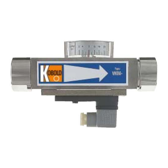
- Page 1 Operating Instructions Viscosity Compensated Flow Meter / Monitor Model: VKM...
-
Page 2: Table Of Contents
EU Declaration of Conformance ..............22 EC-Type Examination Certificate Magnetic reed switch EEx RC ....23 Manufactured and sold by: Kobold Messring GmbH Nordring 22-24 D-65719 Hofheim Tel.: +49(0)6192-2990 Fax: +49(0)6192-23398 E-Mail: info.de@kobold.com Internet: www.kobold.com page 2... -
Page 3: Note
2. Note Please read these operating instructions before unpacking and putting the unit into operation. Follow the instructions precisely as described herein. The devices are only to be used, maintained and serviced by persons familiar with these operating instructions and in accordance with local regulations apply- ing to Health &... -
Page 4: Regulation Use
4. Regulation Use The models VKM are used for measuring and monitoring of viscous liquid flows (max. 540 mm /s). They are suitable for measuring clean and homogeneous fluids which are compatible with on the instrument materials used. If using higher viscosity media, large deviations will occur to the measured val- ues. -
Page 5: Use In Hazardous Areas
5. Use in Hazardous Areas 5.1. General The Flow Meter and Switch do not have a potential igniting source of its own as a mechanical operating device; it does not get any identification according to the guideline 2014/34/EU ("ATEX 100a”). The attachable contact at the sides, being a component of the whole unit, requires certificates and/or approvals. -
Page 6: Potential Equalisation
Read-out edge Read-out edge Flow Direction 5.3. Potential Equalisation The All-metal Flow Meters have to be incorporated in the potential equalisation system of the plant. This is accomplished through connection tube made of metal. 6. Operating Principle A hollow float with a sharp-edged orifice is located within a cylindrical bored metal housing. -
Page 7: Mechanical Connection
7. Mechanical Connection Before installation: It should be confirmed that the maximum allowed operating pressures and operating temperatures of the equipment are not exceeded. (see table: standard material combinations). The instruments may be mounted in any flow direction. No recalibration is required when changing position. -
Page 8: Vkm-1
8.2. VKM-1... and VKM-3... with Ex-contact (cable connection) Special requirements for a safety application The connection of the magnetic switch has to take place in a housing’s, which is in accordance with a norm ignition protection cat. acc. to EN 50014, 1.2. ... -
Page 9: Example For Contact Protective Measures
8.3. Example for Contact Protective Measures For capacitive and inductive loads (long cables and relay/protection) we recommend the following protective schemes. 8.4. ADI-Evaluation Electronics VKM-7.. For connection of the power supply and the output signals please check with the operating instructions of the corresponding ADI electronic. Information! The measuring input of the ADI is already factory- set. -
Page 10: Commissioning
Compact electronic: (..C34P, .. C34N) 9. Commissioning 9.1. General Over-ranging The flow range may be exceeded by a large margin with a non-pulsating flow. Only a certain increase in pressure loss is experienced. (The permissible maximum operating pressure must not be exceeded!). Viscosity range The instrument scale is suitable for a viscosity range of 1 - 540 mm /s. -
Page 11: Adi-Electronic Analyser Vkm-7
Adjustment of the limit values (VKM-3..) With a screwdriver, loosen both mounting screws at the contact. Move the switch housing to the lowest position. After loosening the screws, remove the plug cap from the contact. Connect a suitable multimeter to PIN 1 & 2 (SPDT: contact PIN 2 &... -
Page 12: Technical Information
10. Technical Information Body: VKM-x1...: Brass, nickel-plated VKM-x2...: Stainless steel 1.4301 Screwed fitting: VKM-x1...: Brass, nickel-plated VKM-x2...: Stainless steel 1.4301 Float: VKM-x1...: Brass, nickel-plated VKM-x2...: Stainless steel 1.4301 Orifice: Stainless steel 1. 4310 Spring: Stainless steel 1. 4310 Magnet: Oxide ceramics Seals: VKM-x1...: NBR VKM-x2...: FPM... - Page 13 VKM-7.. Evaluating electronics: Digital indication, bargraph indication or combined indication (digital/bargraph) For technical information please see the operating instructions for ADI. VKM-8.. display: 3-digit LED display indication: semi conductor PNP or NPN Analogue output: 4–20 mA, 3 wire version max. 500 linear Auxiliary power: 24 V +-20%...
-
Page 14: Order Codes
11. Order Codes Viscosity-compensated flow switches model: VKM-1... Measuring Pressure loss Brass Stainless Contact Connection Option Flow P (bar) at range steel special direction L/min oil connect. rated flow* min. max. VKM-1101... VKM-1201... 0.01…0.07 0.02 ..R08 = G 1/4 ..N08 = 1/4 NPT VKM-1102... - Page 15 Viscosity-compensated flow meter with evaluating electronics model: VKM-7... Measuring Pressure loss Brass Stainless Output Connection Flow P [bar] at range L/min steel direction oil approx. rated flow* min. max. Standard Sonder 0.01-0.063 0.02 VKM-7101... VKM-7201..R08 = G 1/4 ..N08 = 1/4 NPT 0.1...0.4 0.03...
-
Page 16: Maintenance
12. Maintenance In cases where the medium to be measured is uncontaminated, the models VKM are almost maintenance-free. However where calcium or dirt deposits form in the housing or other internal parts, the instruments should be regularly cleaned. With a suitable open-ended spanner, remove the instrument from the pipe. After removal of the uppermost threaded connection, the internal parts may be removed for cleaning. - Page 17 VKM-1.., VKM-2.., VKM-3.. VKM-7... VKM-8... VKM K11/0118 page 17...
-
Page 18: Recommended Spare-Parts
Ex contact for VKM-..F0.. Flow direction Housing Meas. “L” 40x40 14. Recommended Spare-Parts Only the instrument parts and material are listed. Depending on the instrument type the parts are available in various sizes (when ordering please indicate instrument type). 1.1) Float Brass 5.1) N/O contact (standard) 1.2) Float Stainless Steel 5.2) Changeover contact (standard) -
Page 19: Declaration Of The Manufacturer (Vkm)
15. Declaration of the Manufacturer (VKM) Declaration for equipment without a potential igniting source according to the explosion protection guideline 2014/34/EU (ATEX 95). We, KOBOLD Messring GmbH, herewith declare that the following units and/or assembly groups: Viscosity Compensated Flow Meter / Monitor model: VKM-*** according to guideline 2014/34/EU, article 1 paragraph 2 and 3 are a. - Page 20 The operation instructions with the broader details listed therein and the installation regulations for the potentially explosive atmosphere should be observed. Some essential measures are: a. The Flow Meter / -Switch has to involved in the potential equalisation system. b. Add-on control contacts can under application of EN 60079-14 article 12.2.1 be used as simple electrical equipment without any additional marking in intrinsically safe equipment.
-
Page 21: Declaration Of The Manufacturer (Ex Rc
16. Declaration of the Manufacturer (Ex RC...) VKM K11/0118 page 21... -
Page 22: Eu Declaration Of Conformance
17. EU Declaration of Conformance We, KOBOLD Messring GmbH, Hofheim-Ts, Germany, declare under our sole responsibility that the product: Flow Meter and Monitor Model VKM to which this declaration relates is in conformity with the standards noted below: EN 61010-1:2011-07... -
Page 23: Ec-Type Examination Certificate Magnetic Reed Switch Eex Rc
18. EC-Type Examination Certificate Magnetic reed switch EEx RC VKM K11/0118 page 23... - Page 24 page 24 VKM K11/0118...
- Page 25 VKM K11/0118 page 25...
- Page 26 page 26 VKM K11/0118...
- Page 27 VKM K11/0118 page 27...
- Page 28 page 28 VKM K11/0118...
- Page 29 VKM K11/0118 page 29...
- Page 30 page 30 VKM K11/0118...
- Page 31 VKM K11/0118 page 31...
- Page 32 page 32 VKM K11/0118...
- Page 33 VKM K11/0118 page 33...
- Page 34 page 34 VKM K11/0118...
Need help?
Do you have a question about the VKM Series and is the answer not in the manual?
Questions and answers