Table of Contents
Advertisement
Quick Links
Motor Driver
Stepper Motor Driver IC EVK
STEPMO_EVK_20x
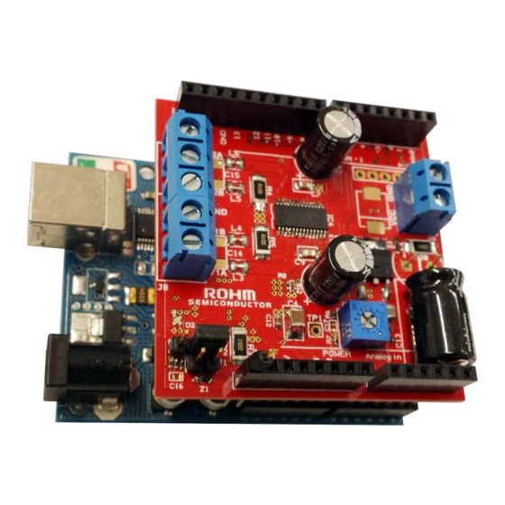
ROHM Stepper Motor Driver IC Evaluation Kit based on Arduino/Genuino Platform
Abstract
●
This evaluation board manual describes the
usage of ROHM's stepper motor driver IC
evaluation kit (EVK) called STEPMO_EVK_20x.
It is designed as a plug-in board (Shield) for
popular Arduino microcontroller platform. This
document provides guidelines to quickly setup
the hardware and software for fast and easy
stepper motor driver IC performance evaluation.
●
Description of Supported ICs
This EVK supports a variety of pin-compatible
ROHM stepper motor driver ICs from standard,
microstep, low voltage and high voltage families
with CLK-IN (clock input) or PARA-IN (parallel
input)
control.
They
constant-current drive with adjustable decay ratio
and the ability for full, half and microstepping.
The ICs feature single supply operation by
integrating the voltage regulator for the low
power logic together with highly efficient DMOS
output power stages. These do not require an
internal charge pump so the motor drivers
achieve low EMI performance. The motor drivers
integrate various protection functions such as
Ghost
Supply
Prevention
Shutdown
(TSD),
(OCP), Under / Over Voltage Lockout (UVLO /
OVLO) high ESD resistance and Pin Short
Protection for robust and reliable operation. The
ICs are housed in compact HTSSOP-B28 power
packages. For further details, please also consult
the
relevant
product
http://www.rohm.com.
www.rohm.com
© 2016 ROHM Co., Ltd. All rights reserved.
EVALUATION BOARD MANUAL
integrate
PWM
(GSP),
Thermal
Over-Current
Protection
datasheets
EVK Key Specifications (Across Model Versions)
●
Input voltage range.............................8~42V
Maximum Output Current Range..........1A~2.5A
Stepping Modes......................... ,½,¼,⅛,
●
EVK Features
Designed as plug-in Shield for Arduino platform
Recommended: Arduino Uno
Several model variants covering wide range of
pin- compatible stepper driver ICs
Support of bipolar or unipolar stepper motors
Adjustable current limit
Adjustable current decay mode
Single supply operation
Stackable design to allow controlling two motors
at
at the same time
Reverse power supply protection
Software library for Arduino IDE
Arduino example programs (Sketches)
Visit
http://www.rohm.com/web/eu/arduino-stepper-motor-shield
for details
1/20
EUDC59-U-002 - Rev. 1.3
Advertisement
Table of Contents

Related Manuals for Rohm STEPMO_EVK_20x


Summary of Contents for Rohm STEPMO_EVK_20x
-
Page 1: Cover Page
EVALUATION BOARD MANUAL Motor Driver Stepper Motor Driver IC EVK STEPMO_EVK_20x ROHM Stepper Motor Driver IC Evaluation Kit based on Arduino/Genuino Platform Abstract EVK Key Specifications (Across Model Versions) ● ● Input voltage range…………………..……8~42V This evaluation board manual describes the usage of ROHM’s stepper motor driver IC... -
Page 2: Table Of Contents
Installation Procedure ..............................15 ● Content of the Software Delivery Package ........................16 ● DEMO Sketch .................................. 16 ● Library function description / FAQ ............................ 17 www.rohm.com 2/20 EUDC59-U-002 - Rev. 1.3 © 2016 ROHM Co., Ltd. All rights reserved. -
Page 3: Safety Instructions
Take care to monitor the PCB and motor driver IC temperature when operating with high load currents and do not exceed the absolute maximum ratings of all components. www.rohm.com 3/20 EUDC59-U-002 - Rev. 1.3 © 2016 ROHM Co., Ltd. All rights reserved. -
Page 4: Introduction
This evaluation board manual describes the usage of ROHM’s stepper motor driver IC evaluation kit (EVK) called STEPMO_EVK_20x. The purpose of the EVK is to allow the test and evaluation of the stepper driver IC in professional research and development environments. It is designed as a plug-in board (Shield) for popular Arduino microcontroller platform. This document provides guidelines to quickly setup the hardware and software for fast and easy stepper motor driver IC performance evaluation. -
Page 5: Model Overview
BOMs of all available model versions please visit http://www.rohm.com/web/eu/arduino-stepper-motor-shield. Main part of the EVK is the ROHM stepper motor driver labelled IC4. Q2, R20 and Z3 form a reverse power supply protection. Z2 is a TVS diode to protect against transient surge voltages. Supply decoupling and filtering is accomplished by C13, L2, and C6-C9. -
Page 6: Schematic
STEPMO_EVK_20x Evaluation Board Manual 3.1 Schematic Figure 2: EVK Schematic – STEPMO_EVK_20x – Page 1 www.rohm.com 6/20 EUDC59-U-002 - Rev. 1.3 © 2016 ROHM Co., Ltd. All rights reserved. - Page 7 STEPMO_EVK_20x Evaluation Board Manual Figure 3: EVK Schematic – STEPMO_EVK_20x – Page 2 www.rohm.com 7/20 EUDC59-U-002 - Rev. 1.3 © 2016 ROHM Co., Ltd. All rights reserved.
-
Page 8: Bill Of Materials
The schematic of the EVK is plotted in Figure 2 and Figure 3. Component values valid for all model versions are annotated, for all other values please refer to the BOM of each model version available at http://www.rohm.com/web/eu/arduino-stepper-motor-shield. 3.2 Bill of Materials The bill of materials is given Table 2 as example for model version 2. -
Page 9: Setup Instruction
TEST11 IC2_X1 IC2_X TEST1 CW_CCW1 IC2_Y1 IC2_Y CW_CCW CLK1 IC2_W1 IC2_W PHASE1 Table 3: Mapping of Arduino IOs to the motor driver IC pins (Master Shield) www.rohm.com 9/20 EUDC59-U-002 - Rev. 1.3 © 2016 ROHM Co., Ltd. All rights reserved. - Page 10 In case a stacked Slave Shield is not used the IOs listed in Table 4 are free to use and can be accessed on the corresponding EVK pin header. However, the additional capacitive load of ~10pF by the turned-off multiplexer path should be considered in this case. www.rohm.com 10/20 EUDC59-U-002 - Rev. 1.3 © 2016 ROHM Co., Ltd. All rights reserved.
-
Page 11: Current Limitation Value
Current Limitation Value The ROHM stepper motor driver ICs supported by this EVK have a current limitation function. This must not to be confused with over current protection (OCP) which is another feature of the IC (check datasheet for details). Instead, the purposes of the current limitation are: ... -
Page 12: Current Decay Mode
Current Decay Mode As explained in the datasheet the ROHM stepper motor driver IC used by this EVK allows external configuration of the current decay mode. It is a way to fine tune the motor performance between vibration and current waveform distortion/harmonics. The optimum decay mode setting depends very much on the application so the influence of each setting should be investigated by lab experiments. -
Page 13: Supply And Motor Connection
Supply and Motor Connection The STEPMO_EVK_20x allows the connection of a 4-wire bipolar or 5-wire unipolar stepper motor to the screw terminal J7/J8. The outputs V1A and V1B belong to one phase of the motor while V2A and V2B to the other. If the motor spins clockwise when it should go counter clockwise the polarity of one phase should be reversed, i.e. -
Page 14: Connection To Microcontroller Motherboard
Turned off / not Not recommended connected Not allowed Not allowed Turned on Allowed Table 10: Matrix of allowed additional Arduino supplies while EVK(s) plugged in www.rohm.com 14/20 EUDC59-U-002 - Rev. 1.3 © 2016 ROHM Co., Ltd. All rights reserved. -
Page 15: Software
Note: It is very important to use the latest IDE version. The provided software library and demo sketches have been tested with Arduino IDE Version 1.6.10. They will not run with older versions such as 1.6.5. The latest ROHM STEPMO_EVK_20x software delivery package can be downloaded here: http://www.rohm.com/web/eu/arduino-stepper-motor-shield Please download it and unzip the package in the subfolder Arduino\libraries\. -
Page 16: Content Of The Software Delivery Package
● Content of the Software Delivery Package The ROHM STEPMO_EVK_20x software delivery package is part of this EVK. It contains the library with all required functions and also some example programs (Arduino Sketches) to demonstrate the usage of this library. -
Page 17: Library Function Description / Faq
● Library function description / FAQ How to define the EVK version? Before including the ROHM steppers library define which stepper motor IC your EVK model is using. E.g. in case of STEPMO_EVK_206 use #define BD63720AEFV See Table 1 for the list of different EVK models. - Page 18 When the instance of ROHM_Stepper class is instantiated with the parameter “TWO” the methods as described in this FAQ are available with the suffixes “_M” and “_S”. These will allow controlling the two shields individually. See sketch examples for references. www.rohm.com 18/20 EUDC59-U-002 - Rev. 1.3 © 2016 ROHM Co., Ltd. All rights reserved.
- Page 19 The user has to bear all responsibility and liability for the proper and safe handling with regard to this DESIGN KIT. The user shall indemnify ROHM from all claims arising from the handling or utilization of the DESIGN KIT. In the case this DESIGN KIT does not comply with the specifications indicated in the Manual, the DESIGN KIT may be returned within 30 days from the date of delivery for a full reimbursement of the purchase price.
- Page 20 Safety-Critical or Life-Critical Applications. If you intend to evaluate the components for possible use in safety critical applications (such as life support) where a failure of the ROHM product would reasonably be expected to cause severe personal injury or death,...
- Page 21 Mouser Electronics Authorized Distributor Click to View Pricing, Inventory, Delivery & Lifecycle Information: ROHM Semiconductor ROHM-STEPMO_EVK_208 ROHM-STEPMO_EVK_20E ROHM-STEPMO_EVK_206 ROHM-STEPMO_EVK_20F ROHM-STEPMO_EVK_205 ROHM-STEPMO_EVK_20C ROHM-STEPMO_EVK_207 ROHM-STEPMO_EVK_20A ROHM-STEPMO_EVK_209 ROHM-STEPMO_EVK_204 ROHM-STEPMO_EVK_203 ROHM-STEPMO_EVK_202...
Need help?
Do you have a question about the STEPMO_EVK_20x and is the answer not in the manual?
Questions and answers