Table of Contents
Advertisement
Advertisement
Table of Contents

Related Manuals for Grundfos SP4


Summary of Contents for Grundfos SP4
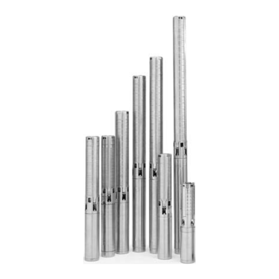
- Page 1 GRUNDFOS INSTRUCTIONS SP4” 4-Inch Stainless Steel Sub mers ible Pumps US Installation and operating instructions WATER QUALITY DRINKING WATER SYSTEM COMPONENTS ANSI/NSF 61 65 GM 30°C/86°F PUMP END ONLY Please leave these instructions with the pump for future reference.
-
Page 2: Safety Warning
If the pump is to be installed in a new well then the well should be fully developed and bailed or blown free of cuttings and sand. The stainless steel construction of the GRUNDFOS submersibles make it resistant to abrasion; however, no pump made of any material can forever withstand the destructive wear that occurs when constantly pumping sandy water. -
Page 3: Pre-Installation Checklist
PRE-INSTALLATION CHECKLIST 4. Splicing the Motor Cable If the splice is carefully made, it will be as efficient as any other portion of the cable, and will be completely watertight. There are a number of cable splicing kits available today – epoxy filled, rubber-sealed and so on. - Page 4 When plastic riser pipe is used, it is recommended that a safety cable be attached to the pump to lower and raise it. The discharge chamber of GRUNDFOS 4-inch submersibles is designed to accommodate this cable. (See Figures 2 & 3.)
-
Page 5: Electrical Connections
INSTALLATION PROCEDURES 4. Electrical Connections WARNING: Reduced risk of electric shock during operation of this pump requires the provision of acceptable grounding. If the means of connection to the supply connected box is other than grounded metal conduit, ground the pump back to the service by connecting a copper conductor (at least the size of the circuit supplying the pump) to the grounding screw provided within the wiring compartment. -
Page 6: Starting The Pump For The First Time
INSTALLATION PROCEDURES Single-Phase 2-Wire Wiring Diagram Three-Phase Wiring Diagram for Submersible Motors for Submersible Motors Single-Phase 3-Wire Control Box for Submersible Motors 4. Starting the Pump for the First Time A. Attach a temporary horizontal length of pipe to the riser pipe. B. -
Page 7: Motor Information
79395511 440/460 1.15 18.0/18.6 1500 1.16 79355512 1.15 14.4 1500 1.84 79395512 *All Grundfos 4” motors have a ground (green wire) GRUNDFOS Control Box SA-SPM5 RATING GRUNDFOS GRUNDFOS GRUNDFOS GRUNDFOS RUN CAP/DELUXE #’s MOTOR MODEL CONTROL BOX STANDARD #’s VOLT... - Page 8 MOTOR INFORMATION The key to long submersible motor life is good cooling. Most submersible pumps rely on moving heat away from the motor by forced convection. The ambient/produced fluid is typically drawn by the motor in the course of pumping to accomplish this task. Submersible motors used in the water supply industry are typically designed to operate at full load in water up to 30°C (86°F), provided the flow velocity can be maintained at a minimum of 0.5 feet per second (fps).
- Page 9 MOTOR INFORMATION Typical Motor Jacket/Shroud Configurations. The motor shroud is generally of the next nominal diameter of standard pipe larger than the motor or the pump, depending on the shroud configuration used. The tubular/pipe material can be plastic or thin walled steel (corrosion resistant materials preferred). The cap/top must accommodate power cable without damage and provide a snug fit, so that only a very small amount of fluid can be pulled through the top of the shroud.
- Page 10 MOTOR INFORMATION Single-Phase 60 Hz MOTOR RATING COPPER WIRE SIZE (AWG) VOLTS 1300 1960 2910 1460 2160 1390 2190 3400 5250 7960 1020 1610 2510 3880 5880 1200 1870 2890 4370 6470 1540 2380 3610 5360 6520 1-1/2 1200 1870 2850 4280 5240...
-
Page 11: Troubleshooting
TROUBLESHOOTING SUPPLY How to Measure What it Means VOLTAGE By means of a voltmeter, which When the motor is under load, the has been set to the proper scale, voltage should be within ± 10% of the measure the voltage at the control nameplate voltage. - Page 12 TROUBLESHOOTING Pump Won’t Start POSSIBLE CAUSE CHECK THIS BY... CORRECT THIS BY... No power at the motor Check for voltage at the control box or panel. If there is no voltage at the control panel, check the feeder panel for tripped circuits and reset those circuits.
- Page 13 TROUBLESHOOTING Fuses Blow or Heaters Trip POSSIBLE CAUSE CHECK THIS BY... CORRECT THIS BY... Improper voltage Check the voltage at the control box or If the voltage varies by more than 10% (+ or panel. -), contact the power company. If the incoming voltage is OK, check the Rewire with correct gauge.
-
Page 14: Limited Warranty
LIMITED WARRANTY Products manufactured by GRUNDFOS are war rant ed to the original user only to be free of defects in material and workmanship for a period of 24 months from date of installation, but not more than 30 months from date of manufacture. GRUNDFOS’ liability under this warranty shall be limited to repairing or replacing at GRUNDFOS’... - Page 15 2941 Brighton Road Oakville, Ontario L6H 6C9, Canada Telephone: (905) 829-9533 Fax: (905) 829-9512 Mexico Bombas Grundfos de Mexico, S.A. de C.V. Boulevard TLC No. 15 Parque Industrial Stiva Aeropuerto Apodaca, N.L. Mexico C.P. 66600 Apodaca, N.L. Mexico Telephone: 011-52-81-8144-4000 Fax: 011-52-81-8144-4010 L-SP-TL-048 Rev.
Need help?
Do you have a question about the SP4 and is the answer not in the manual?
Questions and answers