Table of Contents
Advertisement
Quick Links
Instruction Manual
D104297X012
™
Fisher
V270 Full-Bore Ball Control Valve
Contents
. . . . . . . . . . . . . . . . . . . . . . . . . . . . . . . . .
. . . . . . . . . . . . . . . . . . . . . . . . . . . . .
. . . . . . . . . . . . . . . . . . . . . . . . . . . . . . . . .
. . . . . . . . . . . . . . . . . . . . . . . . . . . . . . .
. . . . . . . . . . . . . . . . . . . . . . . . .
. . . . . . . . . . . . . . . . . . . . . . . . . . . . . . . . . .
. . . . . . . . . . . . . . . . . . . . . . . . . . . . . . . . .
. . . . . . . . . . . . . . . . . . . . . . . . .
. . . . . . . . . . . . . . . . . . . . . . . . . . . . .
. . . . . . . . . . . . . . . . . . . . . . . . . . . . . .
. . . . . . . . . . . . . . . . . . . . . . . . . . .
. . . . . . . . . . . . . . . . . . . . . . . . . . . . . . .
. . . . . . . . . . . . . . . . . . . . . . . . . . . . . . . . . . .
Introduction
Scope of Manual
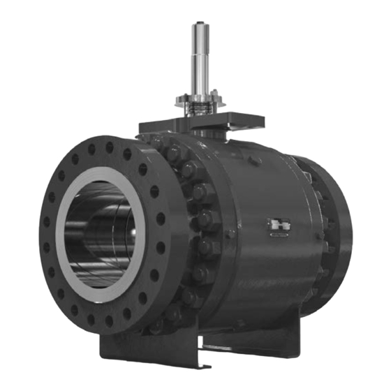
This instruction manual provides installation, operation, maintenance, and parts information for the Fisher V270
Full-Bore Ball control valve (see figure 1). Refer to separate manuals for information concerning the actuator,
positioner, and accessories.
Do not install, operate, or maintain a V270 valve without being fully trained and qualified in valve, actuator, and
accessory installation, operation, and maintenance. To avoid personal injury or property damage, it is important to
carefully read, understand, and follow all the contents of this manual, including all safety cautions and warnings. If you
have any questions about these instructions, contact your
Description
The Fisher V270 is a three piece, trunnion mounted, full-bore control valve designed with features for optimized
pressure, flow and process control. The V270 comes standard with dual seal construction allowing unidirectional or
bidirectional flow and double block-and-bleed operation. The full-bore ball design presents little or no restriction to
flow at full travel. The V270 construction meets ANSI / NACE MR0175 / ISO 15156 as standard.
www.Fisher.com
. . . . . . . . . . . . . . . . . . . . . . . .
. . . . . . . . . . . . . . . . . . . . . . . .
. . . . . . . . . . . . . . . . .
Figure 1. Fisher V270 Control Valve
1
1
1
2
3
3
6
6
6
7
9
11
13
14
14
16
X1492
Emerson sales office
before proceeding.
V270 Valve
September 2018
Advertisement
Table of Contents

Related Manuals for Emerson Fisher V270


Summary of Contents for Emerson Fisher V270
-
Page 1: Table Of Contents
Description The Fisher V270 is a three piece, trunnion mounted, full-bore control valve designed with features for optimized pressure, flow and process control. The V270 comes standard with dual seal construction allowing unidirectional or bidirectional flow and double block-and-bleed operation. The full-bore ball design presents little or no restriction to flow at full travel. -
Page 2: Specifications
Instruction Manual V270 Valve September 2018 D104297X012 Specifications Valve Body Size End Connections NPS 6, J 8, J 10, J 12, J 14, J 16, J 20, Raised Face per B16.5-2013 and J 24. Shaft Connection Style Body/Shell Pressure Rating Keyed CL150, J CL300, and J CL600 Face-to-Face Dimensions... -
Page 3: Educational Services
Instruction Manual V270 Valve D104297X012 September 2018 Educational Services For information on available courses for Fisher V270 valves, as well as a variety of other products, contact: Emerson Automation Solutions Educational Services - Registration Phone: 1-641-754-3771 or 1-800-338-8158 E-mail: education@emerson.com emerson.com/fishervalvetraining... - Page 4 Instruction Manual V270 Valve September 2018 D104297X012 Table 2. Face‐to‐Face Dimensions and Approximate Weights FACE‐TO‐FACE APPROXIMATE WEIGHT DIMENSIONS VALVE SIZE, NPS CLASS Inches Pounds 15.50 15.88 22.00 18.00 19.75 26.00 1020 21.00 22.38 1095 31.00 1640 24.00 1425 25.50 1695 33.00 1050 2320...
- Page 5 Note Standard Fisher V270 live-loaded PTFE packing is composed of partially conductive packing rings (carbon‐filled PTFE male and female adaptors) to electrically bond the drive shaft to the valve body. For hazardous area service, an alternate shaft‐to‐body bonding strap is also available by using the following step (see figure 2).
-
Page 6: Maintenance
Instruction Manual V270 Valve September 2018 D104297X012 Maintenance Valve parts are subject to normal wear and must be inspected and replaced as necessary. The frequency of inspection and replacement depends upon the severity of service conditions. WARNING Avoid personal injury or equipment damage from sudden release of process pressure or uncontrolled movement of parts. Before performing any maintenance operations: D Do not remove the actuator from the valve while the valve is still pressurized. -
Page 7: Replacing Packing
Instruction Manual V270 Valve D104297X012 September 2018 Under normal conditions, the packing nuts should not require re‐tightening. However, when servicing, if the springs do not remain at the target load of 85% compression, retighten the packing box nuts per the following: 1. - Page 8 Instruction Manual V270 Valve September 2018 D104297X012 WARNING D See the WARNING at the beginning of the Maintenance section for more information before removing the valve from the pipeline. D Use proper lifting and rigging practices while moving the valve or valve/actuator assembly. 2.
-
Page 9: Seal Ring Maintenance
Instruction Manual V270 Valve D104297X012 September 2018 7. When the control valve is in operation, carefully examine the packing follower region for any signs of leakage. Seal Ring Maintenance WARNING D See the WARNING at the beginning of the Maintenance section for more information before removing the valve from the pipeline. - Page 10 Instruction Manual V270 Valve September 2018 D104297X012 o‐ring seal (key 14), drive shaft bushing (key 8), and thrust washer (key 9). The two straight pins (key 7) may stay attached to the packing box. c. If necessary, use a punch and drive each straight pin towards the valve side of the packing box to remove. 7.
-
Page 11: Assembly
Instruction Manual V270 Valve D104297X012 September 2018 Valve Assembly Be sure to replace valve parts in the same position and orientation from which they were removed. Use the following steps to reassemble the valve. Note Clean and protect all sealing surfaces from damage while installing parts. Lubricate components when necessary as an aid for installation, and to help protect sealing surfaces. - Page 12 Instruction Manual V270 Valve September 2018 D104297X012 WARNING When lifting the ball, ensure the bearing plates (key 11) are secure on the ball trunnions to prevent parts from falling which may cause personal injury or property damage. 12. Use an approved lifting sling through the ball bore to lift the ball (key 3). a.
-
Page 13: Actuator Mounting
Instruction Manual V270 Valve D104297X012 September 2018 Table 3. Torque Values PACKING BOX HOUSING SOCKET VALVE BODY HEAVY HEX NUT TORQUE HEAD CAP SCREW TORQUE VALVE SIZE, NPS CLASS N•m ft•lbf N•m ft•lbf 1267 1660 1224 2126 1568 1267 3305 2437 2777 2048... -
Page 14: Determining Closed Position
WARNING Use only genuine Fisher replacement parts. Components that are not supplied by Emerson Automation Solutions should not, under any circumstances, be used in any Fisher valve, because they may void your warranty, might adversely affect the performance of the valve, and could cause personal injury and property damage. - Page 15 Instruction Manual V270 Valve D104297X012 September 2018 Figure 4. V270 Exploded View NOTE: 1. KEY NUMBERS 24, 26, 27, 39, 44, 45 AND 46 ARE NOT SHOWN APPLY LUBRICANT GE89572...
-
Page 16: Parts List
Spring Continuous Thread Stud - short Continuous Thread Stud - long Note Heavy Hex Nut Dowel Pin Contact your Emerson sales office for Part Ordering information. Hex Head Pipe Plug NACE Label (not shown) Base Bracket Nameplate (not shown) Description... - Page 17 Instruction Manual V270 Valve D104297X012 September 2018 Figure 5. Fisher NPS 6 CL300 through NPS 24 CL600 V270 Valve Assembly VIEW A VIEW B VIEW A VIEW B SCALE 1:1 SCALE 1:1 GE89573 NOTE: KEY NUMBERS 10, 23, 24, 26, 27, 28, 29, 35, 36, 39, 44 AND 45 ARE NOT SHOWN APPLY LUBRICANT...
- Page 18 Instruction Manual V270 Valve September 2018 D104297X012 Figure 6. Fisher NPS 6 CL150 V270 Valve Assembly VIEW A VIEW B VIEW C VIEW A SCALE 4:1 VIEW C SCALE 2:1 VIEW B SCALE 4:1 GE90204 NOTE: KEY NUMBERS 10, 23, 24, 26, 27, 28, 29, 35, 36, 39, 44 AND 45 ARE NOT SHOWN APPLY LUBRICANT...
- Page 19 Instruction Manual V270 Valve D104297X012 September 2018...
- Page 20 Fisher and ENVIRO-SEAL are marks owned by one of the companies in the Emerson Automation Solutions business unit of Emerson Electric Co. Emerson Automation Solutions, Emerson, and the Emerson logo are trademarks and service marks of Emerson Electric Co. All other marks are the property of their respective owners.
Need help?
Do you have a question about the Fisher V270 and is the answer not in the manual?
Questions and answers