Advertisement
Owner's Manual
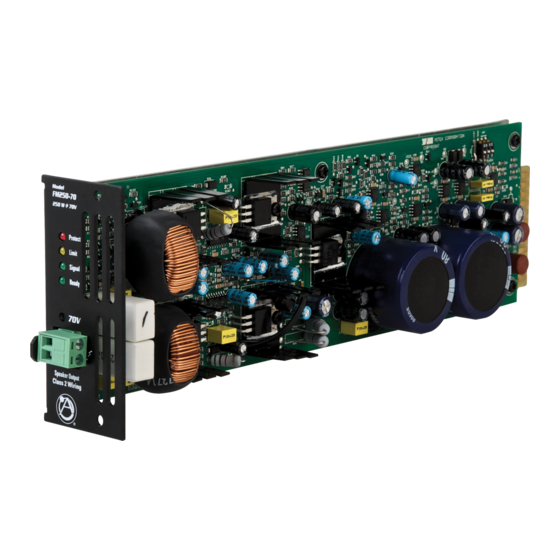
FM250-4 and FM250-70 Module Features
1. Module Status Indicators
Note: They also parallel Status LED on the front panel of the F6-MF panel.
Ready
This LED will illuminate Green when an FM250 power module is installed on the appropriate channel and the F6-MF is
turned on.
Signal
The channel Signal LED will illuminate Green when the FM250 amplifier output signal produces a minimum 1 Watt
output.
Limit
The Limit LED will illuminate Yellow under load conditions. If the FM250 function switch is set to Limit then the LED
acts as a maximum level indicator. If the FM250 channel Limit function is off, the LED reacts as a Clip indicator. Also,
under Low Impedance loads, this LED serves as a current Limit indictor.
Protect
The Protect LED will illuminate Red during one the following conditions. No output will occur while this LED is
illuminated. It will reset itself after the condition has been corrected.
1) Shorted speaker output.
2) Thermal Shut Off. The Temp F6-MF TEMP LED will also be illuminated.
3) Current Overdrive. If the amplifier channel is driving too low of a speaker load.
2. Speaker Connections
A removable Phoenix/Euro Block type connector is supplied to connect your speakers to the FM250 amplifier module. It is
recommended to use 16-gauge wire or lower for connection to the speakers. Note: Do not overload the amp by connecting too many
speakers to the amp.
Multi-Impedance Modular Amplifier
FM250 - 4
250W @ 4Ω
Protect
Limit
Signal
Ready
4Ω
Speaker Output
Class 2 Wiring
1601 Jack McKay Blvd. • Ennis, Texas 75119 U.S.A.
Telephone: 800.876.3333 • Fax: 800.765.3435
– 9 –
Specifications are subject to change without notice.
F6-MF
FM250 -70
250W @ 70V
Protect
Limit
Signal
Ready
70V
Speaker Output
Class 2 Wiring
AtlasSound.com
Advertisement
Table of Contents

Related Manuals for Atlas FM250-4


Summary of Contents for Atlas FM250-4
- Page 1 F6-MF Owner’s Manual Multi-Impedance Modular Amplifier FM250-4 and FM250-70 Module Features FM250 - 4 FM250 -70 250W @ 4Ω 250W @ 70V Protect Protect Limit Limit Signal Signal Ready Ready 4Ω Speaker Output Speaker Output Class 2 Wiring Class 2 Wiring 1.
- Page 2 Owner’s Manual Multi-Impedance Modular Amplifier FM250-4 & FM250-70 Function Switch FM250 Module Dip Switch Functions are located near the rear of the FM250 modules. Note: It is essential to preset your setting prior to inserting the module into the F6-MF .
- Page 3 F6-MF Owner’s Manual Multi-Impedance Modular Amplifier FM250 Amplifier Module Installation Align Modules to Top & Bottom Card Guides Use the following steps and read all steps prior to installation. Turn F6-MF AC Power Switch to the “Off” position. 2. Turn down all level controls on the front panel. 3.
Need help?
Do you have a question about the FM250-4 and is the answer not in the manual?
Questions and answers