Atlas CP700 Owner's Manual
High-performance, dual-channel, commercial audio amplifier
Hide thumbs
Also See for CP700:
- Owner's manual (16 pages) ,
- Specification sheet (2 pages) ,
- Brochure & specs (10 pages)
Table of Contents
Advertisement
Quick Links
CP700 COMMERCIAL
POWER AMPLIFIER
PROTECT
LIMIT
SIGNAL
CH-1
HIGH-PERFORMANCE, DUAL-CHANNEL, COMMERCIAL AUDIO AMPLIFIER
1601 JACK MCKAY BOULEVARD ENNIS, TEXAS 75119 U.S.A. •
©2005 ATLAS SOUND LP
PROTECT
LIMIT
SIGNAL
CH-2
CP700 Commercial Power Amplifi er
Specifications are subject to change without notice
AtlasSound.com
Printed in U.S.A.
OWNER'S MANUAL
CP700
POWER
Commercial Power Amplifier
TELEPHONE: (800) 876-3333 • FAX: (800) 765-3435
ATS002102 RevC 9/05
PP
Advertisement
Table of Contents

Related Manuals for Atlas CP700


Summary of Contents for Atlas CP700
- Page 1 PROTECT LIMIT LIMIT SIGNAL SIGNAL CH-1 CH-2 CP700 Commercial Power Amplifi er HIGH-PERFORMANCE, DUAL-CHANNEL, COMMERCIAL AUDIO AMPLIFIER 1601 JACK MCKAY BOULEVARD ENNIS, TEXAS 75119 U.S.A. • ©2005 ATLAS SOUND LP Printed in U.S.A. CP700 Commercial Power Amplifier Specifications are subject to change without notice AtlasSound.com...
-
Page 2: Table Of Contents
SHOCK HAZARD! The Atlas Sound CP700, when in operation, can produce a shock hazard at the speaker terminals. Make sure the amplifi er is turned off when installing or removing connections at the speaker terminal barrier strip. -
Page 3: Introduction, Features, Applications
POWER AMPLIFIER INTRODUCTION Congratulations and thank you for purchasing the Atlas Sound CP700 dual channel power amplifi er. This product is a professional grade audio power amplifi er specifi cally designed for demanding contractor applications and engineered to provide years of faithful service. Two independent channels driven by separate power supplies ensure maximum channel separation and ultra low distortion fi... -
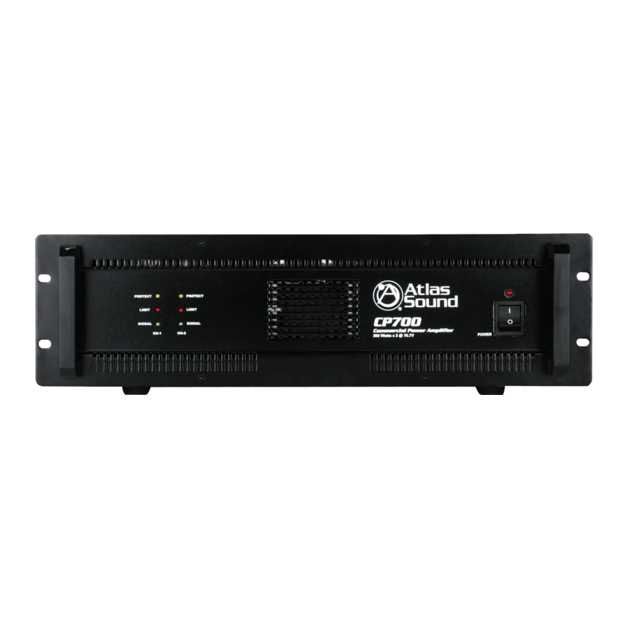
Page 4: Front Panel Description
SIGNAL CH-1 1. Power Switch This rocker switch supplies power to the CP700 amplifi er. A red LED located above the power switch will illuminate when the CP700 is switched on. 2. Protect LED Indicators The CP700 features several types of protection circuitry to prevent damage during turn-on or fault conditions. -
Page 5: Rear Panel Description
POWER AMPLIFIER 4. Limit LED Indicator The CP700 comes equipped with limiter circuitry and LEDs to indicate when this circuitry is activated. The limiter circuitry engages only when the input signals reach a specifi c, factory set magnitude. Once this limit has been reached, the circuitry will reduce the input level enough to prevent clipping at the speaker output terminals. - Page 6 To calculate the maximum quantity of transformer coupled loudspeakers you can safely connect to the CP700, fi rst add up the total number of speakers that will be connected to one channel of the CP700, then multiply that total speaker number by the tap setting you plan to use. The result will be the load in watts that the amp output channel will see.
-
Page 7: Input Wiring
At the input section located on the rear of the CP700, wire the "hot"/positive lead to the "+" terminal, the "cold"/negative lead to the "-" terminal and the shield/drain to the "ground" terminal. -
Page 8: Unbalanced Input
Do not forget to install a jumper wire between the "-" terminal and the ground, as a loss of gain will result without this jumper (Figure 4). White/Red (+) THRU 1601 JACK MCKAY BOULEVARD ENNIS, TEXAS 75119 U.S.A. • ©2005 ATLAS SOUND LP Printed in U.S.A. White/Red (+) Shield Shield... -
Page 9: Speaker Output Wiring
Observe the speaker connection information in the preceeding paragraph (Stereo Direct Coupled Output). With the CP700 turned OFF, move the rear mounted selector switch to the "Parallel" position and connect your mono input wiring to either the channel one or channel two inputs. Both channels will be driven from this mono signal (Figure 6). - Page 10 POWER AMPLIFIER Bridge Mono Configuration (Direct Coupled) If higher power levels are required, the Atlas CP700 can be used in Bridge Mono mode, which utilizes both channels of the amp across the speaker load. With the CP700 turned OFF, move the rear mounted selector switch to the "Bridge" position and connect the input signal to channel one.
- Page 11 To 70.7V speaker load D I R . O U T P U T To 70.7V speaker load 1601 JACK MCKAY BOULEVARD ENNIS, TEXAS 75119 U.S.A. • ©2005 ATLAS SOUND LP Printed in U.S.A. 8, 4, and 2 Ohms AUDIO TRANSFORMER I S O L .
- Page 12 To 100V speaker load D I R . O U T P U T To 100V speaker load 1601 JACK MCKAY BOULEVARD ENNIS, TEXAS 75119 U.S.A. • ©2005 ATLAS SOUND LP Printed in U.S.A. AUDIO TRANSFORMER 8, 4, and 2 Ohms I S O L .
- Page 13 Please observe all necessary safety precautions as the potential for electric shock at the speaker terminals is present. With the CP700 turned off, move the rear mounted selector switch to the "Bridge" position and connect the input signal to channel one. Connect your speaker load across the "+" terminals of both output terminals as follows: •...
- Page 14 CH-2 To 200V speaker load D I R . O U T P U T 1601 JACK MCKAY BOULEVARD ENNIS, TEXAS 75119 U.S.A. • ©2005 ATLAS SOUND LP Printed in U.S.A. 8, 4, and 2 Ohms AUDIO TRANSFORMER I S O L . O U T P U T...
-
Page 15: Specifi Cations
DAMPING FACTOR 8 Ohms Output, 10 Vrms S/N RATIO 8 Ohms per Channel @240W 1601 JACK MCKAY BOULEVARD ENNIS, TEXAS 75119 U.S.A. • ©2005 ATLAS SOUND LP Printed in U.S.A. PROTECTION CIRCUITS Output Offset Voltage Protection Heat Sink Overheat Protection... -
Page 16: Limited Warranty
WARRANTIES OF MERCHANTABILITY AND FITNESS FOR A PARTICULAR PURPOSE. Atlas Sound does not assume, or does it authorize any other person to assume or extend on its behalf, any other warranty, obligation, or liability. This warranty gives you specifi c legal rights and you may have other rights which vary from state to state.
Need help?
Do you have a question about the CP700 and is the answer not in the manual?
Questions and answers