Table of Contents
Advertisement
Quick Links
-
-
-
BESANTEK
-
-
-
-
Digital Low Resistance Ohm Meter
·>•
H
\'
"
BATTERY
CHARGER
-
INSTRUCTION MANUAL
DIGITAL
LOW RESISTANCE
OHM
and CONTACT METER
MtCROPROCESS:)R
CONTROLLED
-
l.
,
OFF
R,
M�NlJ�l
R�NGING
g)
la
Test Equipment Depot - 800.517.8431
99 Washington Street Melrose, MA 02176
TestEquipmentDepot.com
ee
CE
P,
CR:JWEAFI FUSES
MEASUREl,IENT
■
■
(ii)
Ii)
BST-MGR01
C,
CONNECTIONS
+ V
4T
<fl
,-1
•
+.
3T
qt
P1
•
+•
2T
►
,-i-
Q
V
►
I
Pl
Cl
V
•
•
►
I
Advertisement
Table of Contents

Subscribe to Our Youtube Channel
Related Manuals for Besantek BST-MGR01


Summary of Contents for Besantek BST-MGR01
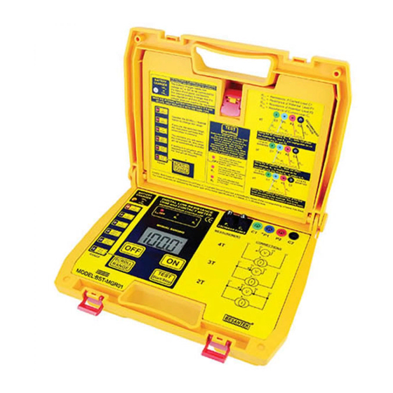
- Page 1 BESANTEK BST-MGR01 Digital Low Resistance Ohm Meter INSTRUCTION MANUAL ·>• DIGITAL LOW RESISTANCE " and CONTACT METER BATTERY MtCROPROCESS:)R CONTROLLED CHARGER CR:JWEAFI FUSES MEASUREl,IENT CONNECTIONS ► M�NlJ�l R�NGING ■ ■ <fl ,-i- • ► (ii) • +• • • ►...
-
Page 2: Table Of Contents
- - - - - BESANTEK - - - - - Index Page 1. Safety Rules............2. Safety Check............3. General Description..........2-4 4. Operating Instructions........... 5-9 5. Display ..............6. Specifications ............11-12 7. C leaning..............12 8. Inside LID Instructions Label......... -
Page 3: Besantek
- - - - - BESANTEK - - - - - - 1. Safety Rules CAUTION /A. RISK OF ELECTRIC l..:n SHOCK T his tester has been designed with your safety in mind. However, no design can completely protect against incorrect use. Electrical circuits can be dangerous and/or lethal when lack of caution or poor safety practices are used. -
Page 4: Safety Check
BESANTEK - - - - - - 2. Safety Check Before using the tester check the condition of the battery. This is done by switching the tester ON. If the BAT LOW symbol appears the battery needs charging. When charging the battery, changing a fuse, or removing the cover to access the internal circuitry, always disconnect the test leads. - Page 5 Resolution on the lowest range is 1µohm and on the highest range, 100 milli-ohm. The meter has 6 measuring ranges, from 2000 micro-ohm to 200.0 ohms. Measurements are displayed on a large 3½ digit custom liquid crystal display. This instrument is powered from it's internal rechargeable battery. It has a regulated DC constant current source with current of 10mA 100mA and 1A.
- Page 6 The I LED is the LED indicating the Constant Current Source being OFF. When this led lights up, it mean that the current injection has been switched OFF (could be over-temperature). The METER has a built-in custom 3½ digit liquid crystal display which can be viewed in most lightning conditions.
-
Page 7: Operating Instructions
- - - - - BESANTEK - - - - - - 4. Operating Instructions The connector for the Battery charger can accept AC or DC signals up to a maximum of 22Vdc. There is a full bridge rectifier inside the tester, as well as a regulated battery charger. - Page 8 BESANTEK - - - - - - Provided, the TESTER is ON, when the TEST Start/Stop is depressed, the selected TEST will start (if stopped) or stop (if in progress). T he TEST Start/Stop also has the EnerSave features. What that mean, is that...
- Page 9 BESANTEK - - - - - - Range Indication by LED: Test Current 1A Resistance 0-20.00mn When this LED lights up, the instrument will � measure up to 19.99mO and will display it as � milli ohms. The resistance which can be measured using this scale/range is from 00.00m to 19.99mO.
- Page 10 BESANTEK - - - - - - Resistance 0-20.000 When this LED lights up, the instrument will measure up to 19.990 and will display it as ohms. 100mA 20.000 The resistance which can be measured using this scale/range is from 00.00 to 19.990.
- Page 11 BESANTEK - - - - - - Main Status Indicators by LED: Constant Current Source Indicator. When this LED lights up, the Constant Current Source is shut down. The Constant Current Source is shut down when • the test is not in progress.
-
Page 12: Display
- - - - - BESANTEK - - - - - -· 5. Display llilli • I J ) 1i-· ..., ..., The HOLD Sign indicator comes on when the readings are held. This happen: At switch "ON", as no reading has been done yet, so the display is on Hold with whatever value when TEST stops. -
Page 13: Specifications
6. Specifications ELECTRICAL Resistance Ranges Range: 0 to 2.000mΩ in steps of 1uΩ 0 to 20.00mΩ in steps of 10uΩ 0 to 200.0mΩ in steps of 100uΩ 0 to 2.000Ω in steps of 1mΩ 0 to 20.00Ω in steps of 10mΩ 0 to 200.0Ω... -
Page 14: Cleaning
ENVIRONMENTAL Operating temperature Range: -15°C to + 55°C Storage Temperature: -20°C to + 70°C GENERAL Safety: EN 61010-1 EN 61326-1 Battery: 12 V rechargeable 12V 2.3Ah Fuses: 1 X 500mA ( Potential Fuse ) 1 X 2A (Current Fuse) Slow Blow, 250V type SPARES AND ACCESSORIES Test Leads Fuses:... -
Page 15: Inside Lid Instructions Label
"' R," Resistance Current lead C :::I The battery charger need• low Resistance of Potential Lead P1 voltage AC or DC lo be connected to Res,stan�e of Potential Lead P2 it'• input (front panel connector). Res,st ance Current Lead The internal banery Charger has it's r... -
Page 16: Terminals Measurement
- - - - - BESANTEK - - - - - - 9. 4 Terminals Measurement C1 TP1 Using the 4 T method, Re,,., does not affect readings R"' are negligeable as no current goes into For measuring low to very low resistance (contact resistance), this... -
Page 17: Terminals Measurement
- - - - - BESANTEK - - - - - - 10. 3 Terminals Measurement Using th e 3T method, R:n does not affect readings. R," is negligeable as no current goes into and P2 but R.,. is added to For measuring low resistance, this measuring method can be utilized C1 and P1 terminals are shorted at the tester. -
Page 18: Terminals Measurement
- - - - - BESANTEK - - - - - - 11. 2 Terminals Measurement Using the 2T method, the resistance test leads are added to readings. This is not recommended for low resistance and long leads. For measuring resistance, this measuring method can be utilized C1 and P1 terminals are shorted, P2 and C2 are shorted at the tester. -
Page 19: Typical Applications
12. Typical Applications Measuring the contact resistance of circuit breakers. Measuring Circuit breaker resistance is very important. If the resistance of a circuit breaker become too large, than, the current going through will warm up the circuit breaker (RxI ) and it could start a fire. -
Page 20: Working Principle Of The Instrument
Measuring the earth mat connections resistance. The Earth mat connections resistance is done using the 4 wires method, to ensure accuracy of these low resistance. The earth mat is connected using very low resistance connections to ensure fault current are passed without or very little resistance. It is very important to measure these connections, using the 4 wires methods, to ensure added accuracy and remove errors from the test leads. -
Page 21: Charging The Battery
BESANTEK - - - - - - 14. Charging The Battery This instrument has an internal rechargeable battery. Only use the supplied battery charger to charge it. To avoid safety issues, do not connect to a device to test or use while re-charging the battery. -
Page 22: The Storage And Maintenance Of Batteries
16. The Storage and Maintenance of Batteries ● The storage temperature range : -15°C~40°C ● Fully charge the rechargeable battery before storage ; if not, the battery life will be shorter. ● The rechargeable battery under storage at ambient temperature of 25°C should be recharged every six months to maintain their quality, performance and reliability.
Need help?
Do you have a question about the BST-MGR01 and is the answer not in the manual?
Questions and answers