
Subscribe to Our Youtube Channel
Related Manuals for Besantek BST-IT11


Summary of Contents for Besantek BST-IT11
- Page 1 99 Washington Street Melrose, MA 02176 Phone 781-665-1400 Toll Free 1-800-517-8431 Visit us at www.TestEquipmentDepot.com BST-IT11 INSULATION CONTINUITY METER INSTRUCTION MANUAL...
-
Page 2: Table Of Contents
INDEX Page Instrument Layout........Introduction..........Safety Notes..........2-3 Features..........Measuring Methods......... 4-7 Specifications.......... 8-10 Maintenance..........11-12... -
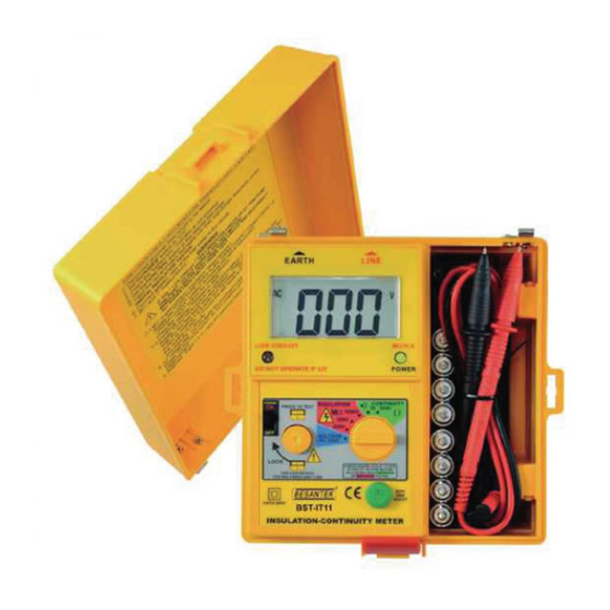
Page 3: Instrument Layout
Instrument Layout OUTPUT OUTPUT Terminal Terminal Display External POWER Voltage Indicator Indicator POWER Switch FUNCTION Switch TEST Button Ω Null Adjust... -
Page 4: Introduction
1. Introduction This meter has been designed and tested in accordance with the CE safety requirements for electronic measuring apparatus, EN61010-1, EN61326-1, and other safety standards. Follow all warnings to ensure safe operation. 2. Safety Notes ● Read the following safety information carefully before attempting to operate or service the meter. -
Page 5: Features
● Observe the International Electrical Symbols listed below. Meter is protected throughout by double insulation or reinforced insulation. Warning! Risk of electric shock. Caution! Refer to this manual before using the meter. Alternating current. 3. Feature ● 3½ digital LCD (2000 counts). ●... -
Page 6: Measuring Methods
4. Measuring Methods OPERATION CAUTION Observe all safety precautions when the FUNCTION switch is set to either the 200MΩ(250,500V) or the 2000MΩ(1000V) position. Connect the meter test leads to the circuit under test before operating the TEST switch. Do not touch the clip ends of the test leads when the TEST switch is pressed. - Page 7 ● TEST switch: The TEST switch is normally OFF, spring loaded, momentary action switch which "turns on" the meter. The momentary action is a safety feature. The test voltage generated by the meter is automatically discharged when the TEST switch is released. Always check the following before testing: The "Battery Low"...
- Page 8 1. Select the required test voltage (250V, 500V or 1000V) by rotating the FUNCTION switch. 2. Connect the test leads to the instrument and to the circuit to be tested.(See connect diagram) If the "LIVE CIRCUIT" is light, do not press the TEST button and disconnect the instrument from the circuit.
- Page 9 When testing is complete ensure that the TEST switch is released before the test leads are disconnected. This is because the system may be charged up and it must be allowed to discharge through the instrument's internal discharge resistor. ● Continuity discharge (Resistance test) Warning Ensure circuit is not live before commencing testing.
-
Page 10: Specifications
5. Specifications Insulation Resistance Test range (DC V) 250V 500V 1000V Measuring Ranges 0-200MΩ 0-2000MΩ Resolution 1 count/100KΩ 1 count/1MΩ Output Voltage on Rated test Voltage + 10% Open Circuit Output Current 1mA DC Power Max. consumption current Consumption Approx. 250mA ±(3%rdg+3dgt) (under 1GΩ/2000MΩ) - Page 11 Continuity Measuring Ranges 0-20Ω 0-2kΩ Resolution 0.01Ω 1Ω Accuracy ±(1.5%rdg ±(1.5%rdg +5dgt) +3dgt) Buzzer Sound Below Under 10Ω ───── Open Circuit Terminal Voltage 4V DC min Short Circuit Terminal Current 210mA DC min. Max. consumption Power Consumption current approx. 160mA Buzzer sounds under 10Ω...
- Page 12 General 170(L)×165(W)×92(D)mm Dimension (with housing front cover) Weight 1040g (batteries included) Power Source 1.5V (AA) × 8 Test leads Instruction manual Accesories Shoulder belt Batteries -10-...
-
Page 13: Maintenance
6. Maintenance Caution Always disconnect the test leads from instrument before batteries or fuse replacement. ● Batteries Replacement: Please replace batteries when the "Battery Low" indicator was shown on the LCD. Disconnect the test leads from the instrument, remove the battery compartment lid and the batteries. -
Page 14: Cleaning And Storage
● Cleaning and Storage Periodically wipe the case with a damp cloth and detergent; do not use abrasives or solvents. If the meter is not to be used for periods of longer than 60 days, remove the batteries and store them separately.
Need help?
Do you have a question about the BST-IT11 and is the answer not in the manual?
Questions and answers